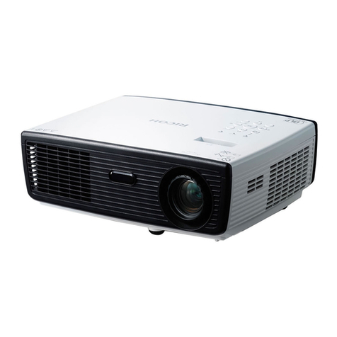
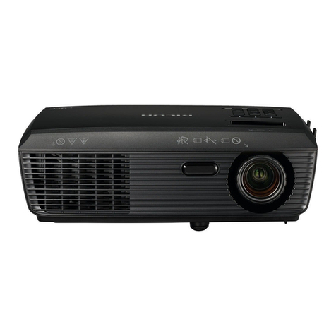
Ricoh Polaris-PJ1 Quick start guide

Polaris-PJ1
Machine Codes:
Y042/Y043/Y044/Y048/Y049
/Y062/Y063/Y064/Y065/Y066
Field Service Manual
1 July, 2014


Important Safety Notices
Prevention of physical injury
1. Before disassembling or assembling parts of the main machine and peripherals, make sure that the
power cord of the main machine is unplugged.
2. The wall outlet should be near the machine and easily accessible.
3. If any adjustment or operation check has to be made with exterior covers off or open while the
main switch is turned on, keep hands away from electrified or mechanically driven components.
• To prevent a fire or explosion, keep the machine away from flammable liquids, gases, and
aerosols.
Health safety conditions
• This machine, which uses a high voltage power source, can generate ozone gas. High ozone
density is harmful to human health. Therefore, the machine must be installed in a well-ventilated
room.
Observance of electrical safety standards
• This machine and its peripherals must be serviced by a customer service representative who has
completed the training course on those models.
Safety and Ecological Notes for Disposal
• Dispose of replaced parts in accordance with local regulations.
1

TABLE OF CONTENTS
Important Safety Notices................................................................................................................................... 1
Important Safety Notices............................................................................................................................... 1
Prevention of physical injury................................................................................................................. 1
Health safety conditions........................................................................................................................1
Observance of electrical safety standards.......................................................................................... 1
Safety and Ecological Notes for Disposal................................................................................................... 1
1. Product Information
Overview.............................................................................................................................................................5
Main Unit........................................................................................................................................................ 5
Control Panel.................................................................................................................................................. 6
Connection Ports.............................................................................................................................................7
Specifications...................................................................................................................................................... 9
General Specifications...................................................................................................................................9
Compatible Mode....................................................................................................................................... 10
2. Installation
Installation Requirements................................................................................................................................. 13
Environment/Power Requirements............................................................................................................. 13
Machine Dimensions................................................................................................................................... 13
Main Machine Installation...............................................................................................................................14
Accessory Check..........................................................................................................................................14
Precautions................................................................................................................................................... 15
Do..................................................................................................................................................................19
Do not........................................................................................................................................................... 19
3. Replacement and Adjustment
Special Tools.................................................................................................................................................... 21
Equipment Needed..........................................................................................................................................22
Parts List.............................................................................................................................................................23
Service Parts List........................................................................................................................................... 23
Replaceable Part Hierarchy............................................................................................................................ 24
Part Replacement..............................................................................................................................................25
Lamp Cover / Lamp Module......................................................................................................................25
Top Cover Unit............................................................................................................................................. 26
Top cover unit...................................................................................................................................... 26
2

Keypad board / IR sensor board......................................................................................................27
Zoom ring............................................................................................................................................ 28
Control panel / Top cover................................................................................................................. 29
Speaker........................................................................................................................................................ 30
Lamp Housing.............................................................................................................................................. 31
Lamp housing.......................................................................................................................................31
System fan / Interlock switch............................................................................................................. 32
LVPS.............................................................................................................................................................. 33
Optical System Unit..................................................................................................................................... 35
Connector list.......................................................................................................................................36
Optical system unit.............................................................................................................................. 37
IO cover / IO seal..............................................................................................................................38
Photo sensor board.............................................................................................................................38
Focus ring.............................................................................................................................................39
Thermistor.............................................................................................................................................39
Color wheel......................................................................................................................................... 40
Optical engine / Main board assembly...........................................................................................42
Blower Fan................................................................................................................................................... 42
Base / Adjustable Foot............................................................................................................................... 43
Required Action After Replacing Parts ...........................................................................................................45
4. Troubleshooting
LED Display.......................................................................................................................................................47
Main Procedures.............................................................................................................................................. 49
Rod Adjustment.................................................................................................................................................52
5. Test & Inspection
Service Mode................................................................................................................................................... 53
How to Enter the Service Mode..................................................................................................................53
Service Mode Settings.................................................................................................................................53
Test Equipment and Conditions.......................................................................................................................58
Test Equipment Needed.............................................................................................................................. 58
Recommended Test Condition.................................................................................................................... 58
Calibration........................................................................................................................................................59
Fan Calibration............................................................................................................................................ 59
3
ADC Calibration.......................................................................................................................................... 60
PC calibration......................................................................................................................................60
Re-write Lamp Hours........................................................................................................................................62
Color Wheel Index.......................................................................................................................................... 65
Test Inspection Procedure................................................................................................................................66
Check points.................................................................................................................................................66
OSD Reset.................................................................................................................................................... 66
6. Update
Firmware Update............................................................................................................................................. 67
Equipment Needed......................................................................................................................................67
Firmware Update Procedure.......................................................................................................................68
DLP composer lite setup procedure .................................................................................................. 68
Get into firmware download mode................................................................................................... 70
USB driver update procedure ...........................................................................................................71
Connect the projector to the PC.........................................................................................................73
Firmware update procedure.............................................................................................................. 74
Check system firmware version..........................................................................................................78
4

1. Product Information
Overview
Main Unit
1. Zoom lever
2. Control panel
3. Connection ports
5

4. Ventilation (inlet)
5. Security chain opening
6. Speaker
7. Remote Receiver
8. Adjustable feet
9. Anti-theft lock hole (KensingtonTM lock)
10. Lens cap
11. Lens
12. Ventilation (outlet)
13. Focus ring
Control Panel
1. Keystone
2. Auto set
3. AV mute
4. Four directional select keys
1. Product Information
6

5. Temp indicator
6. Power indicator
7. Lamp indicator
8. Power
9. Menu
10. Input
11. Enter
Connection Ports
1. S-Video In terminal
2. Monitor Out terminal
3. Computer 1 In terminal
4. Computer 2 In terminal
5. AC In socket
6. HDMI Input terminal
7. Service terminal
8. PC Control terminal
9. Audio 1 In terminal
10. Audio Out terminal
11. Audio 2 In terminal (For Video and S-Video)
12. Video In terminal
Overview
7

• The interface is subject to model’s specifications.
1. Product Information
8

Specifications
General Specifications
No Item Description
1 Dimension (W x D x H) • 314.3 x 223.6 x 88.2 mm (without feet)
• 314.3 x 223.6 x 101.7 mm (with feet)
2 Weight 2.5±0.5Kg
3 Power supply Universal AC: 100V - 240V ± 10%, 50 - 60Hz
4 Power consumption
• Normal mode: 235W+/-10%@110V AC
• ECO mode: 197W+/-10%@110V AC
• Standby mode < 0.5W
5 Keystone correction +/-40 degree
6 Throw ratio 1.95 - 2.15(D/W)@60”
7 Projection lens YM99
8 Offset 115% ±5%
9 Lamp life
Normal mode:
• 4500 hours Standard @190W, 50% survival rate
ECO mode:
• 6000 hours Typical @160W, 50% survival rate
10 DMD chip & Number of
active dots
• 0.55”, S450, Dark Chip 3
• Number of active dots: 800x600
11 System controller TI DDP 4421
12 Video compatibility
• NTSC: M/J, 3.58MHz, 4.43MHz
• PAL: B, D, G, H, I, M, N, 4.43MHz
• SECAM: B, D, G, K, K1, L, 4.25/4.4MHz
• SDTV: 480i/p, 576i/p,
• HDTV: 720p(50/60Hz), 1080i(50/60Hz),
1080p(50/60Hz)
Specifications
9

No Item Description
13 Aspect ratio • 4:3, 16:9, Native, Auto
14 Input signal spec
• VGA-in x2
• Composite Video x1
• S-Video x1
• Audio In(stereo), 3.5mm x1
• RS232 x1
• USB, Type B x1
• HDMI V1.4 x 1
15 Temperature • Operating: 5°C to 40 °C
• Non-operation: -10°C to 60°C
16 Altitude & Temperature
Operating:
• 0 to 2,500 ft, 5°C to 35°C
• 2,500 to 5,000 ft, 5°C to 30°C
• 5,000 to 10,000 ft, 5°C to 25°C
Compatible Mode
Signal Resolution V. Frequency [KHz] H. Frequency [KHz]
VGA
640 x 480 60 31.5
640 x 480 67 35.0
640 x 480 72 37.9
640 x 480 75 37.5
640 x 480 85 43.3
640 x 480 120 61.9
1. Product Information
10

Signal Resolution V. Frequency [KHz] H. Frequency [KHz]
SVGA
800 x 600 56 35.1
800 x 600 60 37.9
800 x 600 72 48.1
800 x 600 75 46.9
800 x 600 85 53.7
800 x 600 120 77.4
XGA
1024 x 768 60 48.4
1024 x 768 70 56.5
1024 x 768 75 60.0
1024 x 768 85 68.7
1024 x 768 120 99.0
SXGA
1152 x 864 70 63.8
1152 x 864 75 67.5
1152 x 864 85 77.1
1280 x 1024 60 64.0
1280 x 1024 72 77.0
1280 x 1024 75 80.0
1280 x 1024 85 91.1
Quad VGA
1280 x 960 60 60.0
1280 x 960 75 75.2
SXGA+ 1400 x 1050 60 65.3
UXGA 1600 x1200 60 75.0
Specifications
11

Signal Resolution V. Frequency [KHz] H. Frequency [KHz]
PowerBook G4
640 x 480 60 31.4
640 x 480 66.6(67) 34.9
800 x 600 60 37.9
1024 x 768 60 48.4
1152 x 870 75 68.7
1280 x 960 75 75.0
iMac DV (G3) 1024 x 768 75 60.0
WXGA
1280 x 768 60 47.8
1280 x 768 75 60.3
1280 x 720 85 68.8
1280 x 720 60 44.8
1280 x 720 120 92.9
1280 x 800 60 49.6
1280 x 900 60 59.9
WSXGA+
1680 x 1050 60 65.3
1080p 60 67.5
1366 x 768 60 47.7
WUXGA 920 x 1200-RB 59.94 74.04
• If the computer compatibility supportive signal is different from User’s Manual, refer to User’s
Manual.
1. Product Information
12

2. Installation
Installation Requirements
Environment/Power Requirements
Operating temperature
5ºC to 40ºC / 41°F to 104°F
Power supply
100 - 240VAC ± 10%, 50 - 60Hz (Auto-ranging and power factor correction)
Machine Dimensions
• With feet: 314.3 x 223.6 x 101.7 mm (W x D x H)
• Without feet: 314.3 x 223.6 x 88.2 mm (W x D x H)
13

Main Machine Installation
The user must set this projector up.
Accessory Check
No Description Q’ty
1 Projector 1
2 Lens Cap 1
3 Remote Control 1
4 Power Cord 1
5 Carrying Bag 1
2. Installation
14

No Description Q’ty
6 CD (*) 1
7 RGB Cable 1
8 Read This First 1
(*) This supplied CD-ROM contains a user’s manual in PDF format.
• Due to different applications in each country, some regions may have different accessories.
Precautions
Please follow all warnings, precautions and maintenance as recommended in this manual to maximize
the life of your unit.
• This apparatus must be earthed.
• Do not look into the projector’s lens when the lamp is on. The bright light may hurt your eyes.
• To reduce the risk of fire or electric shock, do not expose this projector to rain or moisture.
• Do not open or disassemble the projector as this may cause electric shock.
• When replacing the lamp, allow unit to cool down at least 60 minutes, and follow all replacement.
• Do not use lens cap when projector is powered on.
• When the lamp reaches the end of its life, it will burn out and may make a loud popping sound. If
this happens, the projector will not turn back on until the lamp module has been replaced. To
replace the lamp, follow the procedures listed under “Replacing the Lamp”.
Main Machine Installation
15

• Do not remove the cabinet cover, or you may be exposed to dangerous voltage. Refer servicing to
qualified service personnel only.
• This product should be operated only from the type of power source which does not exceed the
voltage range specified on the rating label and the power cord. If you are not sure of the type of
power supply to your home, consult your sales representative or local power company.
• Do not use the polarized plug with an extension cord, receptacle, or other outlet unless the blades
can be inserted completely with three wire grounding type to prevent blade exposure. Failure to
follow these instructions may result in fire or electric shock.
• Plastic bags can be dangerous; please do not leave near babies and young children. To avoid the
threat of suffocation, please keep away from their nose and mouth.
• Do not ingest battery, Chemical Burn Hazard. The remote control supplied with this product
contains a coin cell battery. If the coin cell battery is swallowed, it can cause severe internal burns
in just 2 hours and can lead to death. Keep new and used batteries away from children. If the
battery compartment does not close securely, stop using the product and keep it away from
children. If you think batteries might have been swallowed or placed inside any part of the body,
seek immediate medical attention.
• Installing the Projector on a Wall or Ceiling:
1. Do not attempt to clean or replace parts for a machine that is installed in a high location on a
wall or ceiling. Doing so may cause it to fall down, resulting in an injury.
2. Do not open the lamp cover of a machine that is installed on a wall or ceiling. Doing so may
cause the lamp cover to fall down. If the lamp is broken, pieces of glass may fall and cause
an injury.
3. Contact your sales or service representative to clean or replace parts for a machine that is
installed on a wall or ceiling.
4. If a machine is incorrectly installed on a wall or ceiling, it may fall down and cause an injury.
Contact your sales or service representative if you want to install a machine on a wall or
ceiling.
5. Do not obstruct the machine's vents. Doing so risks fire caused by overheated internal
components.
2. Installation
16

6. For users, do not install the projector by yourself. Contact your sales or service representative
if you want to install the projector on a wall or ceiling.
7. For sales or service representatives:
• Use brackets that are strong enough to support the projector. The projector weighs about
2.6 kg (5.75 lb.).
• The projector must be installed in a location that is sturdy enough to support the full
weight of the projector and brackets.
• Use only the screws (three M4×16 screws) provided with the projector to attach the
brackets to the projector.
• Use all three of the projector's screw holes to attach the brackets. The locations of the
screw holes are shown in the illustration below. Make sure that the screws are tightened
firmly.
• This projector will detect the life of the lamp itself. Be sure to change the lamp when it shows
warning messages.
• Never operate this unit on AC power during a thunderstorm. If you see lightning or hear thunder,
never touch the unit, cables and/or peripherals. An electric surge caused by the storm, may result
in an electrical shock or damage to the unit.
• Never push objects of any kind into this product through openings as they may touch dangerous
voltage points or short-out parts that could result in a fire or electric shock. Never spill liquid of any
kind on the product.
• Do not place or keep the projector within the reach of the children. It may fall or tip over, possibly
causing serious injury.
• Do not stack other equipment on this product and do not place this product on other equipment.
The top and bottom surface of this product increase in temperature during normal use and may
damage the other unit.
• Do not use attachments not recommended by RICOH. Use of incompatible attachments could
cause hazards or damage to the product.
Main Machine Installation
17

• Do not place this product on an unstable cart, stand, tripod, bracket, or table. The product may
fall, causing serious injury to a child or adult and serious damage to the product.
• Unplug this product from the wall outlet and take the product to qualified service personnel if you
encounter any of the following conditions:
1. The power supply cord or plug is damaged.
2. Liquid has been spilled, or objects have fallen into the product.
3. The product has been exposed to rain or water.
4. The product does not operate normally when following the operating instructions. Adjust only
those controls that are covered by the operating instructions.
5. The product has been dropped or damaged in any way. (If the cabinet should break, please
handle with care to avoid injury.)
• This product incorporates glass components, including a lens and a lamp. If these should break,
please handle with care to avoid injury and contact your sales representative for repair service.
Avoid any broken pieces of glass since they may cause injury. In the unlikely event that the lamp
ruptures, thoroughly clean the area around the projector and discard any edible items placed in
that area since they may be contaminated.
• Do not place anything in front of the lens while the projector is operating. Things placed in front of
the lens may overheat and burn or start a fire.
• Unauthorized substitutions may result in fire, electric shock, or other hazards. (Only the
replacement of the lamp should be made by users.)
• Upon completion of any service or repairs to this product, ask the service technician to perform
safety checks to verify that the product is in proper operating condition.
• Do not leave thermal paper documents or easily deformed items on top of the unit or near the air
exhaust for long periods of time.
• The heat from the unit could erase the information on the thermal paper, or cause deformation or
warping.
2. Installation
18
This manual suits for next models
10
Table of contents
Other Ricoh Projector manuals

Ricoh
Ricoh PJ LU8000 Series User manual

Ricoh
Ricoh PJ WX5350N Operating manual

Ricoh
Ricoh PJ WX4130n User manual

Ricoh
Ricoh PJ WX5140 User manual

Ricoh
Ricoh PJ X3340 Guide

Ricoh
Ricoh Leo-C2/P2 Service manual

Ricoh
Ricoh PJ X5360N User manual

Ricoh
Ricoh PJ WX4141n User manual

Ricoh
Ricoh PJ X4340 User manual

Ricoh
Ricoh PJ WX5361N Operating manual

Ricoh
Ricoh PJ WX4130n User manual

Ricoh
Ricoh Y017 Manual

Ricoh
Ricoh PJ HDC5420 User manual

Ricoh
Ricoh PJ WX5361N User manual

Ricoh
Ricoh PJ WUL5970 Series User manual

Ricoh
Ricoh PJ X3340 User manual

Ricoh
Ricoh Y024 Quick start guide

Ricoh
Ricoh PJ WX4152NI User manual

Ricoh
Ricoh PJ RU7700L Series User manual

Ricoh
Ricoh PJ WX4240N User manual