manuals.online logo
Brands
  1. Home
  2. •
  3. Brands
  4. •
  5. Ridetech
  6. •
  7. Automobile Accessories
  8. •
  9. Ridetech LevelTow 81234006 User manual

Ridetech LevelTow 81234006 User manual

Congratulations - your new LevelTow Helper Springs are quality products capable
of improving the handling and comfort of your vehicle. As with all products, proper
installation is the key to obtaining all of the benefits your kit is capable of delivering.
Please take a few minutes to read through the instructions to identify the components and
learn where and how they are used. It is a good idea to start by comparing the parts in
your kit with the parts list below.
Components Part# QTY
Hardware
WARNING!
'RQRWLQÀDWHWKLVDVVHPEO\ZKHQLWLV
XQUHVWULFWHG7KHDVVHPEO\PXVWEHUHVWULFWHGE\
WKHVXVSHQVLRQRURWKHUDGHTXDWHVWUXFWXUH'R
QRWLQÀDWHEH\RQG36,,PSURSHUXVHRU
RYHULQÀDWLRQPD\FDXVHSURSHUW\GDPD HRU
VHYHUHSHUVRQDOLQMXU\
81234006 13-15 RAM 3500, 13 RAM 2500
´%$,/&/$03  
´)/$7:$6+(5  
´;´)/$1*(/2&. 
´)/$1*(187  
´+(;187   
´67$5:$6+(5  
00;00)/$7+'%2/7 
1</217,(:5$3     
$,5635,1*    
833(5%5$&.(7   
/2:(5%5$&.(7   
$;/(%5$&.(7   
+($76+,(/'   
IW78%,1*   
7+(50$/6/((9(  
FIGURE “A”
NOTE:
Both illustrations are of the left, or driver’s
side, of the vehicle. Reverse any orientations when
assembling and installing the right, or passenger,
side of the vehicle.
3/4" STAR
WASHER
PUSH-TO-CONNECT
ELBOW FITTING
3/4"-16 NUT
AIR
SPRING
COMBO STUD
BUTTON
STILL HAVE QUESTIONS?
Tech line hours
0RQGD\)ULGD\$P30(67
NOTE:
Please read thorough this manual completely before installing the air
spring kit on your vehicle.
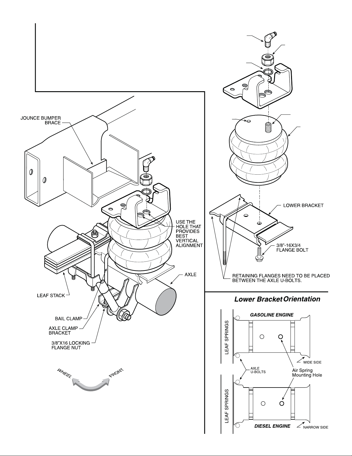
STEP 1 — PREPARE THE VEHICLE
With the vehicle on a solid, level surface chock the front wheels.
Remove the negative battery cable. Your vehicle is equipped with
rubber jounce bumpers. The jounce bumpers are bolted to the frame
above the axle. Remove the jounce bumpers from the vehicle.
STEP 2 — PRE-ASSEMBLE THE KIT
Select a lower bracket from your kit and determine which side of the
Figure
“A”. NOTE: The smaller side is for the gasoline engine axle and
the larger side is for Diesel engine axle.Select one air spring, bail
clamp and lower bracket from your kit. Place the bail clamp in the
correct position in the slot of the lower bracket for your vehicle. Install
the air spring to the lower bracket using the hole for your vehicle with
Please
see the lower right section of Figure “A”. The bolt will be tightened
up in STEP 5.
STEP 3 — INSTALLING THE UPPER BRACKET TO THE
VEHICLE
Select an upper bracket from your kit. Install the upper bracket to the
Figure “A”.
STEP 4—INSTALLING THE ASSEMBLY TO THE VEHICLE
Position the lower bracket and air spring assembly from STEP 2 on
the axle as shown in Figure “A”. Put the large threaded stud though
the large hole on the upper bracket and the locating pin of the air
spring in the small hole on the upper bracket as shown in Figure “A”.
Make sure the aliment pin is in the locating hole before fasting
air spring to the upper bracket. Fasten the air spring to the upper
bracket using ¾"-16 hex head nut and ¾" star washer. Fasten the
lower bracket to the axle housing using the bail clamp and the axle
securely to engage the orange thread sealant.
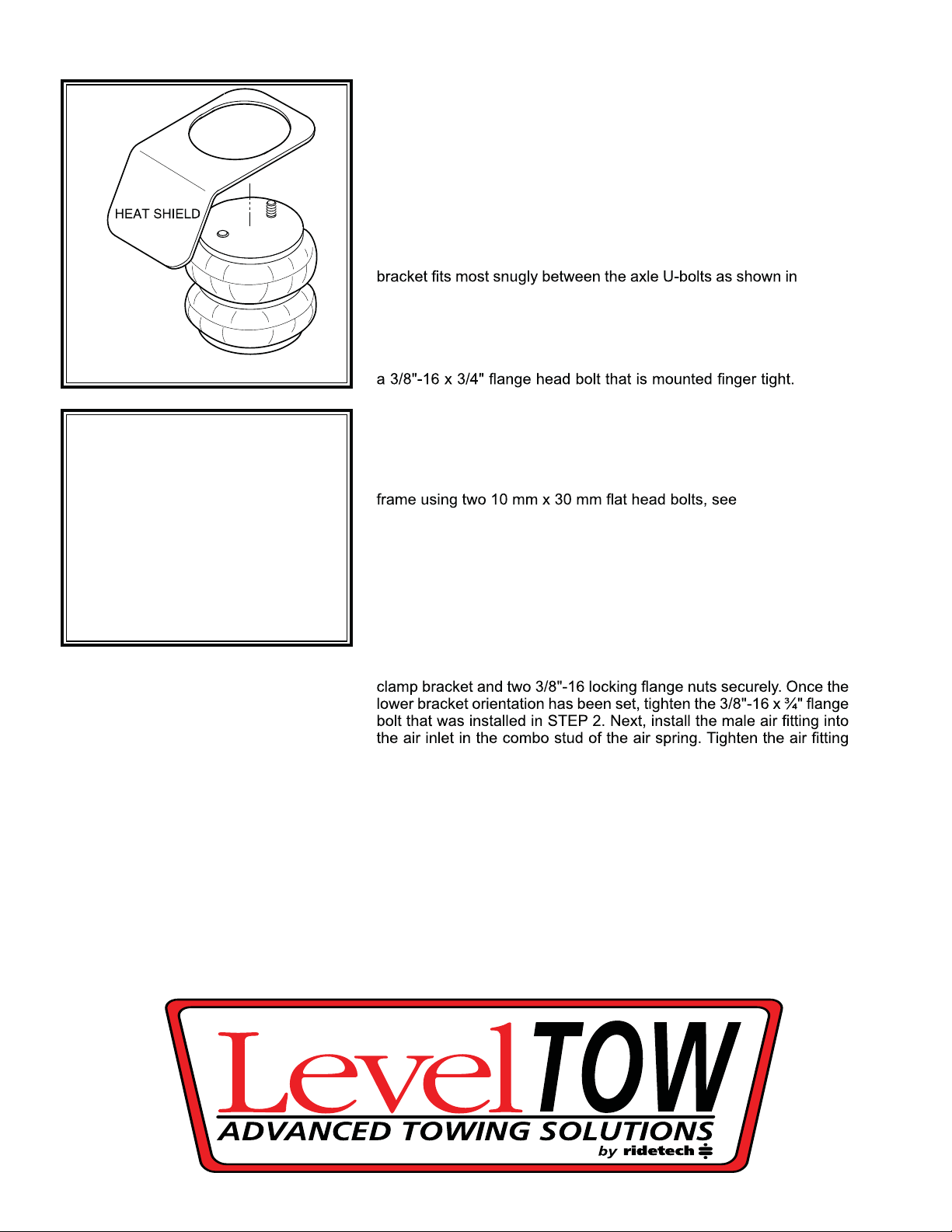
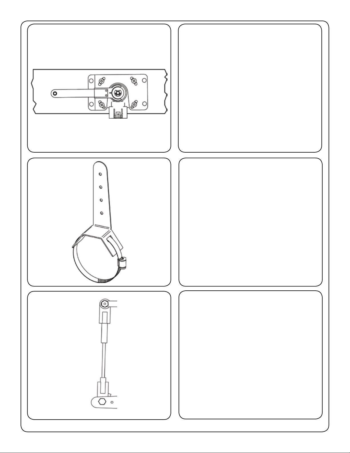
STEP 5— INSTALLATION OF THE PASSENGER’S SIDE
ASSEMBLY
Before following STEPS 1-4 with reverse orientations for assembly
and installation of the passenger’s assembly, a heat shield will need
to be mounted between the upper bracket assembly and the top plate
of the air spring, see Figure “B”. Position the heat shield directly
between the closest heat source and the air spring. Ensure that the
heat shield will not interfere with normal operation of the air spring
or the vehicle’s suspension. Do not position the heat shield directly
above the axle, as it may contact the axle on full suspension travel.
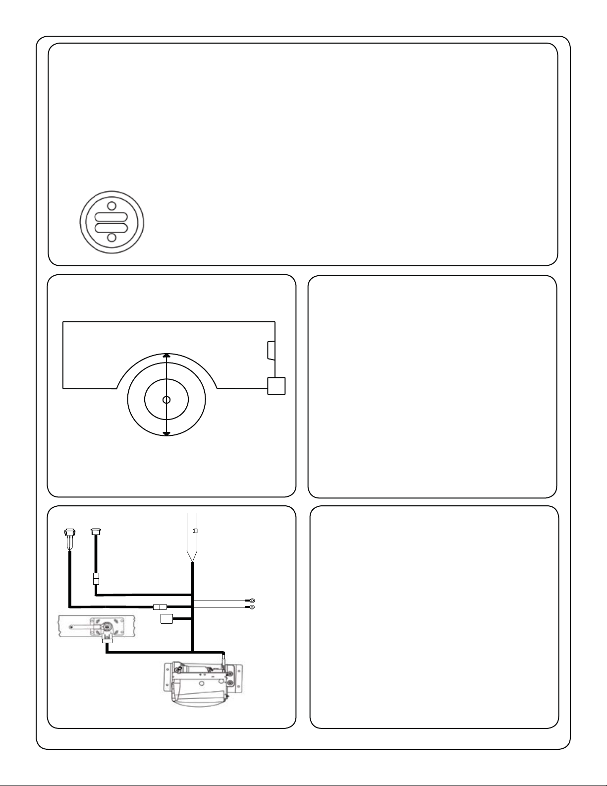
FIGURE “B” (Step 5)
Important:
In order for the air spring
to function properly, there
must be a minimum of 1/2"
of clearance around the air
spring.
LevelTow Compressor System
Congratulations - your new LevelTow Compressor System is a quality product, that when used in conjunction with the
LevelTow helper Air Springs, is capable of improving the handling and comfort of your vehicle. As with all products, proper

through the instructions to identify the components and learn where and how they are used. It is a good idea to start by
comparing the parts in your kit with the parts list below.
Components: Part # QTY
Compressor Unit 31920012 1
Smart Sensor Height Sensor 70010596 1
Compressor Mounting Bracket 90002440 1
Smart Sensor Mounting Bracket 70010596 1
Sensor Linkage 31980001 1
Linkage Axle Bracket 70011429 1
Control Panel Bracket 70011439 1
Airline Adapter (mounted to compressor) 70011436 1
Airline Cartridge Fitting (mounted in compressor) 31954500 1
Main Activation Switch 35970000 1
Manual Control Switch 70011413 1
Main Wire Harness 31900051 1
Axle Bracket Clamp 99000005 1
1/4” TEE Fitting 31954400 1
1/4” Fitting for airsprings Straight / 90 Degree 31954000 / 31954201 2
Heat Shrink tubing for Sensor linkage 90002030 2
20 amp fuse 90001922 1
Fuse Holder 90001924 1
10-12 Butt Connector for Fuse Holder 90001913 1
Ring Terminal for Main Power Hookup 90001916 1
Hardware:
#10 x 5/8” Phillips pan head - sensor to bracket 99104002 4
1/4”-14 x 1” Self Drilling Screw- Sensor and Compressor to Frame 99254001 10
The LevelTow Compressor System is an automatic leveling system, once it is turned on(button
illuminated blue) it will operate without any assistance.

to keep the vehicle level. It has a dwell range built in so that when the truck is going down the
road hitting small defects the system will be idle. It isn’t until the sensor gets out of this dwell
range for 18 seconds that the system will react.
The activation switch has to be illuminated blue for the system to work.
Activation Button
1. Before you install the compressor system,
you will need to have the helper Airsprings
installed. This will ensure that the LevelTow
linkage does not get in the way of the Air-
springs.
        
vehicle at ride height, measure the lip of
the fender to the ground at the center of the
wheel and write it down.
Measurement_________________
This measurement will be used as a refer-
ence once you have the compressor system
installed.
2. Unpack the wiring for the LevelTow sys-
tem and lay it out. This will give you an idea
to where you can mount the components
without having to modify the wiring harness.
NOTE:
There is a wiring diagram on Page 7 to assist
you in component location.
Red Wire
20 Amp
Fuse
Activation
Switch
Manual
Inate/Deate
GREEN
BLACK
BLUE
White
4 pin plug
Black
10 pin plug Gray
4 pin plug
Relay
Black 3 pin plug Black Wire
Black Wire
System
Ground
Yellow Wire
Battery
(Needs to go to Battery under hood)
Keyed Power
(Should only have power with key on)
(these wires
can be attached
at the same point)
Page 5
3. Remove the nut from the stud on the com-
pressor that is sticking down. Stick the studs
into the holes on the keyhole slots and slide
the compressor into the locked position. Re-
install the nut and tighten. Tighten the nuts
on the bottom of the studs also. This will se-
cure the compressor to the frame mounting
plate.
NOTE:
The diagram shows the position the com-
pressor goes onto the plate.
4. With the nuts secured the compressor will

will pull down against the mounting plate.
5. The compressor needs to be mounted
on the frame rail with the opening up. The
rubber shield will protect it from road debris.
Attach the compressor bracket to the frame
with 4 self drilling screws supplied in the kit.
NOTE:
Before drilling any hole be sure to check and
see if there are any brake lines, fuel lines, or
wires on the other side of the surface you are
drilling.
Page 6

on the frame and out of direct tire spray. The
hose on the drain should be coming straight
out of the bottom. There is a drain in the bot-
        
that might get into the housing. Be sure that

ing to the compressor assembly.
7. The Axle bracket can be mounted in any
location on the axle tube to get the sensor
linkage to line up. The Axle mount should
be mounted on the axle so that the linkage
will line up from the axle mount to the sensor.
Keep this in mind when establishing the sen-
sor location.
8. The next step will be to mount the sen-
sor. The Smart Sensor needs to be centered
in its travel at the trucks ride height to oper-
ate properly. This can be done by cutting the

loosening the 4 sensor mounting screws and
twisting it in the mount and retightening the
4 screws. When the mounting and linkage
is done it should look like the diagram seen
here.
Page 7
9. The sensor needs to be mounted on the
frame rail with the wires pointing down. The
arm will need to swing up opposite the direc-
tion of the wires as the suspension is being
compressed. Attach the sensor bracket to
the frame with (4) self drilling screws sup-
plied with the kit.
NOTE:
The sensor can be mounted on the inside or
outside of the frame. Make sure the linkage
and arm can go through its entire travel with-
out hitting any obstructions
10. This diagram shows how the clamp
sticks through the axle bracket. Loosen the
clamp until it will open up and then slide it
through the bracket. The whole assembly
can then be put on the axle tube. Reinsert
the end of the clamp back into the adjuster
and tighten the clamp until the bracket is
tight on the axle tube.
11. With the sensor and the axle bracket
mounted, it is time to connect the 2 with the
supplied linkage. The linkage is a universal
length and will have to be cut to achieve the
necessary length for your application. To do
this it will be necessary to have the truck sit-
ting at its factory ride height. With the truck
at ride height center the sensor in its travel.
The rod can slide into each rubber rod end
up to 1”.
Page 8
12. The 2 pieces of heat shrink supplied in
the kit will hold the linkage together after your
length is determined. To apply the heat shrink
slide one piece over the rubber endlink as far
as it will go on to the rod side. Heat the heat
shrink      with a heat
gun(hair dryer or small torch will work) until it
shrinks down to the rubber. Continue heating
the heat shrink to the rod until secured. Be
sure not to over heat the tubing causing it to
pull from the rubber end.
13. Mount the control panel in a convenient
location. Install the Power Button and Manu-
al Control Rocker into the panel. The Power
Button gets installed into the round hole. The
nut that is on the button is used to attach the
button in the panel. The Rocker Switch goes
into the hole with the notch in it. Align the
tab on the switch with the slot and push the
switch into the hole until it snaps in place.
The rocker will only go into the hole one way.
You can also custom mount the buttons if de-
sired. They both use a 3/4” hole. The hole
for the manual switch will have to have a slot
for the tab
14. Hook the wires up to the manual control
switch as shown in the diagram.

Black Wire -Switch Supply

GREEN
BLACK
BLUE
Page 9
TOP
Red Wire
20 Amp
Fuse
Activation
Switch
Manual
Inate/Deate
GREEN
BLACK
BLUE
White
4 pin plug
Black
10 pin plug Gray
4 pin plug
Relay
Black 3 pin plug Black Wire
Black Wire
System
Ground
Yellow Wire
Battery
(Needs to go to Battery under hood)
Keyed Power
(Should only have power with key on)
(these wires
can be attached
at the same point)
Red Wire - This wire needs to go straight to the Battery with the fuse holder installed within 18”
of the Battery
Yellow Wire - This wire needs to go to a switched 12 volt power source. This wire should only
have power when the key is on.
Black Wires - These wires go to a chassis ground. They can go to one of the screws attaching
the compressor to the frame.
Relay - Will need to be attached to the frame with a self drilling screw supplied in the kit..
Page 10
16. Once the system is installed you can ver-
ify the operation of the system by putting a
load on the truck. With a load on the truck
and the button illuminated blue, your fender
to ground measurement that you took on the

or lower you can adjust the height by loos-
ening the 4 screws that attach the sensor
to the bracket and twist in its mount. If ride
height can not be achieved by adjusting in
the bracket the linkage will need to be length-
ened or shortened to achieve the height you
need.
Page 11
AIR LINE
AIR
SPRINGS
COMPRESSOR
AIR LINE “T” FITTING
15. . Start at the Airspring fur-
thest from the compressor. Trim the airline so that the cut is clean and as square as possible.

the airspring to the compressor keeping it away the exhaust pipe and sharp edges. If it is neces-
sary to run the line over a sharp edge, use a supplied thermal sleeve over the airline to protect
it. The sleeve is installed by sliding it over the airline to the area where the line needs protected.
The airline should not be bent or curved sharply, this can cause the line to buckle or kink.

to the compressor, trim off the excess and use it for the remaining air spring line to the compres-


TIP: 

Manual Operation:
The LevelTow Compressor System also has a manual control function. This function allows you to manually



Note:
If the Activation Button is illuminated blue and the manual button is pushed the truck will relevel itself. The
activation button has to be off for the manual control to be used and the truck remain at the height.
Troubleshooting:

direction. You can verify this by turning the truck on and check that the activation button is illuminated blue.
Unhook one end of the linkage and move the sensor arm by hand. If when you move the arm down (Keep in


ness at the sensor. To do this, with the truck turned off, simply unplug the harness from the sensor. Using
a small screwdriver pop the purple retainer out of the plug by prying up on each end of it. After removing the
retainer if you look into the end of the plug you will see a tang holding each wire terminal. Simply pry it down
just enough to release the terminals of the blue and green wires. Swap the blue and green wire postion and
reinstall the wires into the plug paying attention to the direction of the small tab on the wire terminal. This
tab will point to the center of the plug. Push the wire terminals into the plug making sure they catch on the


correctly, shut the truck off and reattach the linkage.
STILL HAVE QUESTIONS?
Tech line hours
Monday-Friday
8AM - 6PM (EST)...........812-482-2932
Page 12
#82010009
RED
RED
BLACK
BLUE
GREEN
VIEW FROM WIRE SIDE
WIRE SIDE
SIDE VIEW
WIRE LOCATIONS AT HEIGHT SENSOR

Other Ridetech Automobile Accessories manuals

Ridetech 41583000 User manual

Ridetech

Ridetech 41583000 User manual

Ridetech MuscleBar 11289100 User manual

Ridetech

Ridetech MuscleBar 11289100 User manual

Ridetech 11059121 User manual

Ridetech

Ridetech 11059121 User manual

Ridetech RidePRO-X User manual

Ridetech

Ridetech RidePRO-X User manual

Popular Automobile Accessories manuals by other brands

CYBEX SIRONA M2 i-SIZE user guide

CYBEX

CYBEX SIRONA M2 i-SIZE user guide

Intellitronix DP3001 installation guide

Intellitronix

Intellitronix DP3001 installation guide

Brink 4517 Fitting instructions

Brink

Brink 4517 Fitting instructions

Hamron 609-206 User instructions

Hamron

Hamron 609-206 User instructions

STEINBAUER 220733 Installation

STEINBAUER

STEINBAUER 220733 Installation

rockymounts HighNoon FC Add-On installation instructions

rockymounts

rockymounts HighNoon FC Add-On installation instructions

Directed 403.SUBARU2 installation guide

Directed

Directed 403.SUBARU2 installation guide

Thule 2056 parts list

Thule

Thule 2056 parts list

Directed DS3+ installation guide

Directed

Directed DS3+ installation guide

Hamg Shing KBT120N user guide

Hamg Shing

Hamg Shing KBT120N user guide

Fimer FLEXA AC Stand Alone installation manual

Fimer

Fimer FLEXA AC Stand Alone installation manual

Aries S223044 installation manual

Aries

Aries S223044 installation manual

rough country 921106090 manual

rough country

rough country 921106090 manual

HUSKY LINERS 7391 Care and use instructions

HUSKY LINERS

HUSKY LINERS 7391 Care and use instructions

TAUBENREUTHER 16- 5830 instruction manual

TAUBENREUTHER

TAUBENREUTHER 16- 5830 instruction manual

Farad BARS PR25 - 2 quick start guide

Farad

Farad BARS PR25 - 2 quick start guide

HUSKY LINERS 47901 installation instructions

HUSKY LINERS

HUSKY LINERS 47901 installation instructions

Kargo Master 40933 Instruction guide

Kargo Master

Kargo Master 40933 Instruction guide

manuals.online logo
manuals.online logoBrands
  • About & Mission
  • Contact us
  • Privacy Policy
  • Terms and Conditions

Copyright 2025 Manuals.Online. All Rights Reserved.