Ridge Tool Company 9
prevents others from accidentally contacting the ma-
chine or workpiece and either causing the equipment
to tip or becoming entangled in the rotating parts.
5. If mounted on a 1406 Folding Wheel Stand, make
sure 1460 Oil Pan Cover is removed.
6. If necessary, fill the reservoir with RIDGID Thread
Cutting Oil.
7. Make sure OPEN/OFF/CLOSE switch is in the OFF
position.
8. Position the foot switch so that the operator can
safely control the machine, tools and workpiece. It
should allow the operator to do the following:
•Stand facing the directional switch.
•Use the foot switch with his left foot.
•Have convenient access to the directional switch
and tools without reaching across the machine.
Machine is designed for one person operation.
9. Plug the threading machine into the electrical outlet
making sure to position the power cord along the
clear path selected earlier. If the power cord does not
reach the outlet, use an extension cord in good con-
dition.
To avoid electrical shock and electrical
fires, never use an extension cord that is damaged or does
not meet the following requirements:
•The cord has a three-prong plug similar to shown
in Electrical Safety section.
•The cord is rated as “W”or “W-A”if being used
outdoors.
•The cord has sufficient wire thickness (14 AWG
below 25’/12 AWG 25’-50’). If the wire thickness is
too small, the cord may overheat, melting the cord’s
insulation or causing nearby objects to ignite.
To reduce risk of electrical shock, keep all
electrical connections dry and off the ground. Do not
touch plug with wet hands.
10. Check the Threading Machine to insure it is operating
properly.
•Flip the control switch to CLOSE. Press and release
the foot switch. Check that the Threading Machine
rotates in a counterclockwise direction as you are
facing the front chuck and that the jaws close down
toward center. Have the Threading Machine ser-
viced if it rotates in the wrong direction or if the foot
switch does not control its stopping or starting.
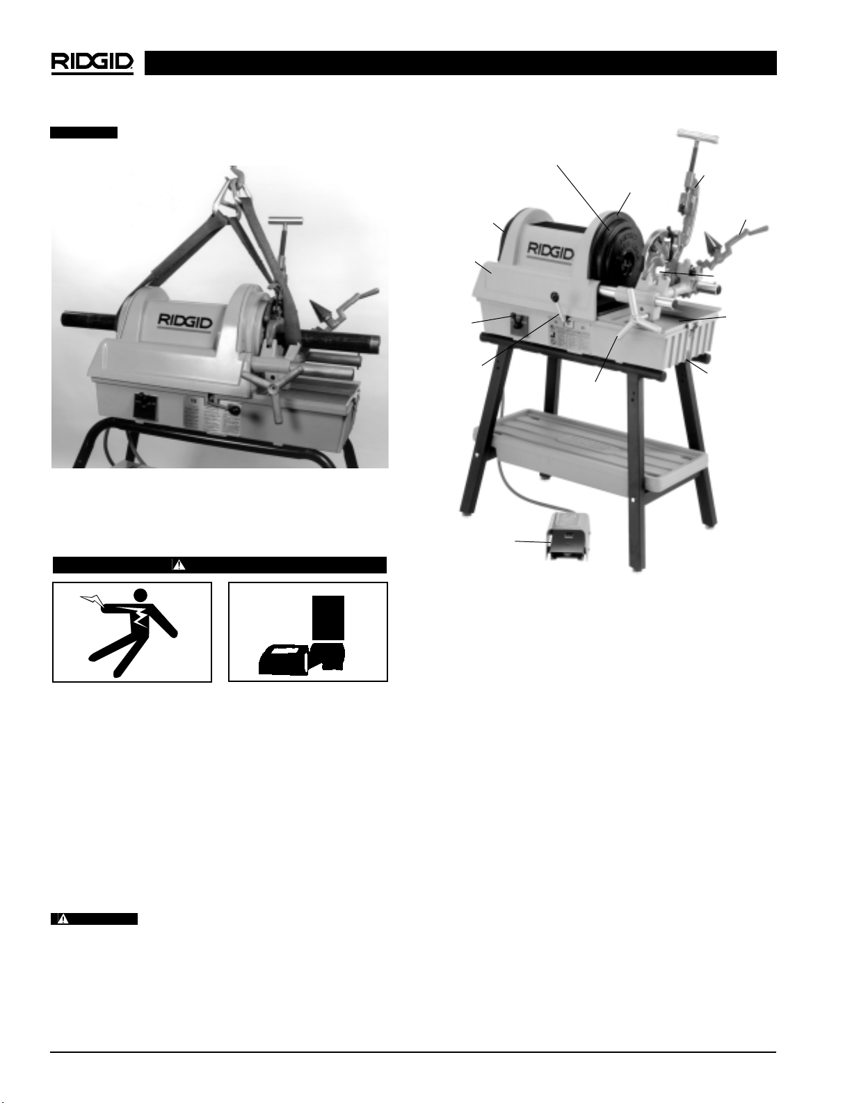
1822-I Pipe and Bolt Threading Machine
NOTE! High speed dies are recommended for use with
this machine when threading 1″- 2″pipe at 45
RPM. Because of its high speed, alloy dies will
wear quickly and produce poor quality threads.
11. Clean metal shavings and other debris from the chip
tray of the Threading Machine. Check the level and
quality of the thread cutting oil. Replace or add oil if
necessary. Reservoir in the base will hold approxi-
mately one (1) gallon of thread cutting oil.
NOTE! Thread cutting oil lubricates and cools the threads
during the threading operation. A dirty or poor
grade cutting oil can result in poor thread quality.
NOTE! For improved thread quality use RIDGID Stain-
less Steel Oil and thread at 16 RPM.
NOTE! To drain dirty oil and properly maintain the oil
system, refer to the “Maintenance Instructions”.
Machine and Work Area Set-Up
WARNING
To prevent serious injury, proper set-up of the ma-
chine and work area is required. The following pro-
cedures should be followed to set-up the machine.
1. Locate a work area that has the following:
•Adequate lighting
•No flammable liquids, vapors or dust that may ignite.
•Grounded electrical outlet
•Clear path to the electrical outlet that does not
contain any sources of heat or oil, sharp edges
or moving parts that may damage electrical cord.
•Dry place for machine and operator. Do not use the
machine while standing in water.
•Level ground
2. Clean up the work area prior to setting up any equip-
ment. Always wipe up any oil that may have splashed
or dripped from the machine to prevent slips and
falls.
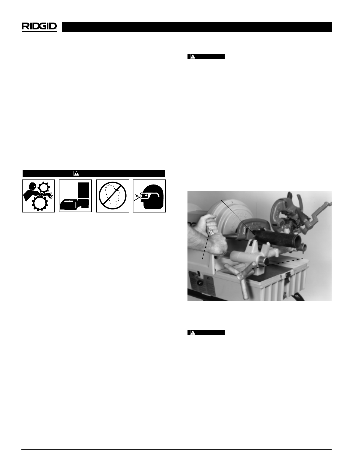
3. If the workpiece extends more than four (4) feet be-
yond the Threading Machine, use one or more pipe
stands to prevent tipping and the oscillation of the
pipe.
4. If the workpiece extends beyond the Threading
Machine, set-up guards or barricades to create a
minimum of three (3) feet of clearance around the
Threading Machine and workpiece. This “safety zone”
WARNING
WARNING