Riello 20081467 User manual

PT EN
Cod. Doc-0091238 Rev. 0
HYDROLINE
COMANDO A BORDO PARA INSTALAÇÕES
DE 2 TUBOS
1. Advertências preliminares
Estas instruções são parte integrante do manual do
aparelho no qual o KIT é instalado. Consulte este manual
para as ADVERTÊNCIAS GERAIS e REGRAS FUNDAMENTAIS DE
SEGURANÇA.
Em algumas partes do manual são utilizados os símbolos:
ATENÇÃO = para ações que exigem cautela especial e
preparação adequada.
PROIBIDO = para ações que não devem absolutamente
ser executadas.
2. Versões
Códigos
20081467 Comando Plus a bordo 2T
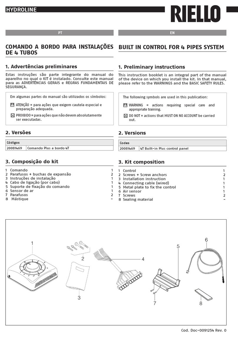
3. Composição do kit
1 Comando 1
2 Parafusos + buchas de expansão 2
3 Instruções de instalação 1
4 Cabo de ligação (por cabo) 1
5 Suportedexaçãodocomando 1
6 Sensor de ar 1
7 Parafusos 2
8 Mástique -
BUILT IN CONTROL FOR 2 PIPES SYSTEM
1. Preliminary instructions
This instruction booklet is an integral part of the manual
of the device on which you install the kit. In that manual,
please refer to the WARNINGS and the BASIC SAFETY RULES.
The following symbols are used in this publication:
WARNING = actions requiring special care and
appropriate training.
DO NOT = actions that MUST ON NO ACCOUNT be carried
out.
2. Versions
Codes
20081467 2T Built-in Plus control panel
3. Kit composition
1 Control 1
2 Screws + Screw anchors 2
3 Installation instruction 1
4 Connecting cable (wired) 1
5 Metal plate to fix the control 1
6 Air sensor 1
7 Screws 2
8 Sealing material -

PT EN
Cod. Doc-0091238 Rev. 0
HYDROLINE
4. Comando a bordo da máquina
Abra o comando, removendo o parafuso de segurança
colocado lateralmente. Efetue a ligação do cabo
fornecido, tal como na figura (3a) de acordo com o tipo
de comando escolhido.
Insira o sensor de temperatura (A) no respetivo conector
CN1, coloque o jumper JP1, tal como indicado na figura
(2a).
Se necessário, configure os jumpers PS (C).
Volte a fechar o comando com o parafuso de segurança
removido anteriormente.
Desligue a alimentação elétrica.
Remova o painel móvel.
Aceda à parte superior do quadro elétrico colocando
o comando tal como indicado na fig 1, inserindo-o
nas respetivas linguetas e bloqueando-o com os dois
parafusos fornecidos.
Abra o quadro elétrico da unidade e efetue as ligações
à régua de terminais, tal como indicado na figura (4a).
Insira os dois conectores de 4, 6 polos, tal como indicado
na figura 4A.
Por fim, fixe, com o mástique fornecido, o sensor de ar
perto do ventilador (consulte o manual de instalação da
unidade).
Linha contínua Cablagem da empresa fabricante
Linha tracejada Cablagem do instalador
IFM Motor do ventilador
FC Condensador do motor ventilador
EV Eletroválvula
EC Contacto externo
TB Régua de terminais
CF/CM Conectores do motor
CS Mudança de estação remota
* Opcional
** Não utilizados
AS Sensor de ar
WS Sensor de água
A Castanho
B Azul
C Preto
R Vermelho
W Branco
O Laranja
V Roxo
D Azul claro
Y Amarelo
Y/G Amarelo/verde
G Cinzento
4. Unit-mounted control
Open the control by removing the side security screw.
Connect the cable supplied as shown in the attached
gure(3a)accordingtothetypeofcontrolchosen.
Insert the temperature sensor (ref.A) into the
corresponding CN1connector, position the JP1 jumper as
showninthegure(2a).
Ifnecessary,congurethePSjumpers(refC).
Close the control using the security screw which had
been removed before.
Disconnect the power supply.
Remove the cabinet.
Access the upper part of the electrical panel positioning
the control as shown in gure 1. It has to be inserted
in the dedicated tabs and secured with the two screws
provided.
Open the electrical panel of the unit to connect the
terminalboxasshowningures4aand4b.Insertthe
twoconnectorswith4or6polesasindicatedingure
4A.
Finally, secure the air sensor near the fan using the
sealing material provided (see the installation manual
of the unit).
Continuous line Factory wiring
Dotted Line Wiring by others
IFM Fan motor
FC Fan motor capacitor
EV Solenoid valve
EC External contact
TB Terminal block
CF/CM Motor connector
CS Remote change over switch
* Optional
** Non usate
AS Air sensor
WS Water sensor
A Brown
B Blue
C Black
R Red
W White
O Orange
V Violet
D Light blue
Y Yellow
Y/G Yellow/Green
G Gray

PT EN
Cod. Doc-0091238 Rev. 0
HYDROLINE
UNIDADE-UNIT

PT EN
Cod. Doc-0091238 Rev. 0
HYDROLINE
IT EN
TO ELECTRONIC CONTROL - PARA O COMANDO ELETRÓNICO

PT EN
Cod. Doc-0091238 Rev. 0
HYDROLINE
1
2
5
IT EN
4
9
3
8
6
7
5. Funções
O comando é utilizado nas instalações de 2 tubos.
O comando mantém a temperatura interior, definida
através do manípulo, entre 10 °C e 30 °C.
6. Ventilação
Através do botão de seleção da velocidade do ventilador,
é possível selecionar, manual ou automaticamente, o
modo de funcionamento do ventilador.
No modo manual é possível escolher três tipos de
velocidade baixa/média/alta) de acordo com as
necessidades ou o modo económico.
No modo automático, a velocidade do ventilador é
regulada pelo microprocessador do comando, com base
na temperatura escolhida.
Contudo, durante a instalação, é possível selecionar a
ventilação contínua, atuando nos microinterruptores
presentesnaplacaeletrónica(verconguraçãodosjumpers).
Através do respetivo sensor (opcional), é possível excluir a
ventilação quando no modo de aquecimento a temperatura
da água é inferior a 35 °C e no modo de arrefecimento é
superior a 18 °C.
Estas duas funções permitem obter um maior conforto
durante o funcionamento no inverno, evitando
ventilações indesejadas, enquanto que no modo de
verão, permitem o desligamento e a ligação automática
de todos os ventiloconvectores, de acordo com a
temperatura da água.
1 Botão POWER
2 LED azul função arrefecimento
3 Botão FAN
4 LED vermelho função aquecimento
5 Botão MODE
6 LED verde função poupança de energia
7 Manípulo da temperatura
8 LED amarelo função seleção automática da velocidade
do ventilador
9 LEDS vermelhos função velocidade do ventilador
5. Functions
Control is used in 2-pipe systems.
Control have a knob to select the temperature, with a
range from 10°C to 30°C, and room temperature is
maintained at the selected value.
6. Fan operation
Use the speed selection button of the fan to select the
manual or automatic operating mode of the fan.
In manual mode, it is possible to select three fan speeds
(low/medium/high) according to the need, or the
economy mode.
In the auto mode fan speed is regulated by a
microprocessor in the control in relation to the
temperature chosen.
During installation, it is possible to select continuous
fan operation via the switch located on the electronic
board (see section dipswitch configuration).
As an option, fan operation can be disabled during
heating by means of a sensor if water temperature is
below 35°C, and during cooling if water temperature is
above 18°C.
These two functions allow improved comfort levels
during winter by avoiding undesired fan operation
and during summer by turning the fan coils on and off
automatically in relation to the water temperature.
1 POWER button
2 Blue LED - cooling operation
3 FAN button
4 Red LED - heating operation
5 MODE button
6 Green LED - energy saving operation
7 Temperature knob
8 Yellow LED - fan automatic speed selector
9 Red LEDs - fan speed operation

PT EN
Cod. Doc-0091238 Rev. 0
HYDROLINE
7. Frost - protection
This function keeps the temperature from dropping below
7°C in rooms not used for long periods of time.
When this temperature is reached, the control activates
the valve and puts the fan on high speed.
The frost protection function can be activated
through the associated micro-switch (see section
dip-switch conguration); if enabled, this function
activates even when the control is in the OFF position.
8. Energy saving
This function is especially useful when air conditioning at
night or in rooms where the user is likely to be absent for
a longer period of time.
In this case, by selecting the function e and pressing the
FAN button repeatedly it is possible to raise the setpoint
temperature by 4°C in cooling mode and reduce it by 4°C
in heating mode.
Enabling this function (Green LED ON) cuts out other
displays.
9. Seasonal changeover
Manual
Selection of heating/cooling is done manually by pushing
the button on the control.
Centralised
Centralised seasonal changeover can be done in two ways:
by a switch located on the central control panel that
allowsheating/coolingmodechangeover;
by a temperature sensor (Accessory) located in contact
with the entering water pipe.
In this last mode, fan coil operation is driven by the control,
in cooling or heating, depending on the temperature read
by the sensor.
Switch and sensor operate on 230V power supply, so both
must be adequately insulated.
If the seasonal manual changeover button is pushed
while the centralised changeover mode is activated, the
correspondingLEDwillbrieyashwhilemaintainingthe
activated mode.
In any case, centralised changeover takes priority over
local changeover.
10. External contact
The control has an input that can be used as window
contact or presence detection (see wiring diagram). When
such a signal is activated (presence of line voltage on the
terminal block contact) the control is set to OFF (open
window) or to Energy Saving (empty room), depending on
thecontrolconguration.
If the control is set to OFF, as a consequence all outputs
are disconnected (fan, valves, etc.) and only the frost
protection function is active if it has been enabled by its
corresponding dip-switch. If the control is set to Energy
Saving, the internal temperature is raised by 4°C in cooling
mode and reduced by 4°C in heating mode.
To switch from one operating mode to the other, keep the
Power button and the speed selection button pressed for
at least 5 seconds.
7. Anticongelamento
A função anticongelamento permite evitar, em ambientes
não frequentados durante longos períodos, que a
temperatura desça abaixo de 7 °C.
Quando esta temperatura é alcançada, o controlo ativa a
válvula e o ventilador na velocidade alta.
Afunçãoanticongelamentopodeserativada,congurando
o respetivo microinterruptor (ver conguração dos
jumpers). Se estiver habilitada, também está ativa com o
comando na posição OFF.
8. “Energy saving” (poupança de energia)
Esta função é particularmente útil durante o funcionamento
à noite ou nos ambientes climatizados nos quais se espera
estar ausente durante um certo período de tempo. Nesse
caso, selecionando a função, premindo repetidamente a
teclaFAN,épossívelaumentar4°Catemperaturadenida
durante a operação no modo de arrefecimento e reduzir
4 °C a temperatura durante a operação no modo de
aquecimento. Ativando esta função (LED verde aceso) as
outras exibições são excluídas.
9. Mudança de estação
Manual
A seleção aquecimento/arrefecimento, é efetuada
manualmente com o botão no comando.
Centralizada
A mudança sazonal centralizada pode ser efetuada de
duas formas:
através de um comutador posicionado na central de
comando que permite comutar o modo de aquecimento/
arrefecimento;
através de uma sonda por contacto (Acessório) a
posicionar na tubagem de entrada da água.
Neste último modo, o funcionamento do ventiloconvector
é comandado pelo comando no aquecimento ou no
arrefecimento de acordo com a temperatura detetada
pelo sensor.
Tanto o comutador, como a sonda funcionam a 230 V, pelo
que devem estar adequadamente isolados. Se premir a tecla
de mudança sazonal manual enquanto a mudança sazonal
centralizada está ativa, provoca uma breve intermitência do
LED relativo ao modo de funcionamento ativo.
De qualquer forma, a mudança sazonal centralizada exclui
o funcionamento da mudança sazonal local.
10. Contacto externo
O comando está equipado com uma entrada para ser
utilizada como contacto janela ou sensor de presença (ver
esquema elétrico).
Quando este sinal é ativado (presença do potencial de
linha no contacto da régua de terminais), o comando
é colocado em OFF (janela aberta) ou em Poupança de
energia(ambiente desocupado), dependendo de como o
comando está congurado. Se o comando estiver em OFF,
todas as saídas são desativadas (ventiladores, válvulas,
etc.) e apenas a função anticongelamento permanece ativa
se habilitada pelo respetivo jumper. Caso o comando seja
colocado em Energy Saving, a temperatura interna aumenta
4 °C no arrefecimento e diminui 4 °C no aquecimento.
Aalteraçãodeconguraçãoentreestasduaspossibilidades
de funcionamento é efetuada premindo, continuamente,
durante pelo menos 5 segundos, o botão Ligar e o botão
de seleção de velocidade.

PT EN
Cod. Doc-0091238 Rev. 0
HYDROLINE
Amudançadeconguraçãoéacompanhadaporumsinal
luminoso, 3 intermitências do LED verde para a transição
daconguraçãoOFFparaPoupançadeenergiaeLEDverde
aceso durante 3 segundos para a transição oposta.
11. Modo “Noite” e “Obscurecimento”
Após 10 segundos, em que as teclas e o manípulo não são
premidos pelo utilizador, os LEDs diminuem a intensidade
da luz emitida, de modo a prejudicar menos a vista. Este
efeito é designado por modo “Noite”. Selecionando-o,
é possível obscurecer completamente a luz LED (modo
“Obscurecimento”).
A seleção do modo “Obscurecimento” é efetuada,
posicionando a velocidade do ventilador no máximo e
mantendo premida durante 5 segundos a tecla de seleção
da velocidade do ventilador. A seleção é indicada por 4
intermitências do LED vermelho que indica a velocidade
máxima do ventilador.
Com uma operação análoga, é possível retornar ao modo
“Noite”. Neste caso, a seleção é acompanhada por 3
intermitências do mesmo LED.
12. Função dos botões
POWER
Este botão é utilizado para ligar e desligar o comando. Uma
vez desligado, todas as funções são desativadas, mas o
comando continua alimentado com 230 V.
Se a função anticongelamento (frost-protection) for
selecionada com o microinterruptor especíco, continua
ativa mesmo quando o comando está desligado.
MODE
Este botão é utilizado para alterar manualmente o modo
de funcionamento, de arrefecimento para aquecimento e
vice-versa.
FAN
Este botão é utilizado para selecionar manualmente a
velocidade do ventilador (baixa, média e alta velocidade).
Continuando a premir este botão, é possível selecionar a
escolha automática da velocidade do ventilador, gerida
pelo microprocessador.
Se este modo de funcionamento for selecionado, o LED
amarelo acende-se. Além disso, sempre com o mesmo
botão, é possível selecionar também o modo Energy Saving,
no qual a temperatura desejada no ambiente aumenta 4 °C
no arrefecimento e diminui 4 ° C no aquecimento. O modo
Poupança de energia é acompanhado pelo acendimento
do LED verde.
13. Seletor de temperatura
Permite regular a temperatura desejada. O valor de
referência no centro da escala é de 20 °C.
Rodando o manípulo para o símbolo ( – ) obtém-se uma
redução do valor da temperatura definida (valor mínimo
de 10 °C).
Rodando o manípulo para o símbolo (+) obtém-se um
aumento do valor da temperatura definida (valor máximo
de 30 °C).
Theswitchingfromonecongurationtotheotherissignalled
by a light. The Green LED ashes 3 times when switching
from OFF to Energy Saving and the same green LED remains
ON for 3 seconds when switching from Energy Saving to OFF.
11. “Night” and “Darkening” mode
If the buttons and the knob are not pressed or used for
10 seconds, the light is dimmed by the LEDs to reduce the
disturbing light. This function is called “Night” mode. By
a special selection, the LEDs light can be fully darkened
(“Darkening” mode).
The “Darkening” mode can be selected by setting the fan
speed to its maximum value and keeping the selection
buttonoffanspeedpressedfor5seconds.4ashesofthe
red LED indicate the fan maximum speed.
With the same operation it is possible to return to “Night”
mode.
Inthiscase,thesameLEDisashing3times.
12. Button operation
POWER
This button is used to turn the control on and off. When it
is OFF, all functions are disconnected but the control is still
powered at 230V.
If the frost protection function is selected by the special
microswitch, this function is activated even if the control
is off.
MODE
This button is used to manually switch from cooling to
heating mode and vice versa.
FAN
this button is used to select the fan speed manually (low,
medium and high speed).
Keep on pressing this button to select the automatic fan
speed selection, which is controlled by the microprocessor.
If this operating mode is selected, the yellow LED is on.
Moreover, by using the same button it is possible to select
the Energy Saving function where the room temperature
required is raised by 4°C in cooling mode and reduced by
4°C in heating mode. The green LED turns on when the
Energy Saving mode is active.
13. Selettore temperatura
Its purpose is to maintain the temperature at the desired
level. The reference value at the centre of the range is
20°C. By turning the knob towards the symbol ( – ) the
temperature is reduced from the original setting (minimum
value is 10°C).
By turning the knob towards the symbol ( + ), the
temperature is raised from the original setting (maximum
value is 30°C).

PT EN
Cod. Doc-0091238 Rev. 0
HYDROLINE
14. Indicadores luminosos
LED azul
Aceso Indica que o comando está no modo de
arrefecimento ( ).
Intermitente Indica que o comando está no modo
anticongelamento ( ).
LED vermelho (grupo da direita)
Aceso Indica que o comando está no modo de
aquecimento ( ).
Intermitente Indica a presença de uma anomalia
(sonda interrompida).
LEDS vermelhos (grupo da esquerda)
Aceso Indica que o ventilador está a funcionar
na velocidade selecionada.
LED AMARELO
Aceso Indica que a seleção da velocidade
dos ventiladores é determinada
automaticamente ( ).
LED verde
Aceso Indica que o comando está no modo
Energy
Saving (poupança de energia)
( )
.
Intermitente Indica que o comando está no modo OFF
forçado pelo contacto externo.
LED vermelho/azul
Intermitente Indicam que o comando está no modo
“Autoteste”.
15. Funções dos “jumpers”
(microinterruptores)
Jumper n.º 1 (P1)
Na posição de contacto aberto, permite a ativação da
função anticongelamento (
).
Jumper n.º 2 (P2)
Na posição de contacto aberto, permite que ventilador
funcione à velocidade selecionada, mesmo que a
temperatura de setpoint tenha sido atingida.
Jumper n.º 3 (P3)
Na posição de contacto aberto, limita o campo de
regulação do manípulo da temperatura, de acordo com os
seguintes limites:
Arrefecimento: temperatura mínima selecionável: 23 °C.
Aquecimento: temperatura máxima selecionável: 21 °C.
Jumper n.º 4 (P4)
Na posição de contacto aberto, permite ativar o
ventilador em intervalos de tempo regulares, mesmo
que a temperatura de setpoint (Air sampling) tenha sido
atingida.
14. Light indicators
Blue LED
ON
Indicates that the control is in cooling
mode ( ).
Flashing Indicates that the control is in frost
protection mode ( ).
Red LED (group on the right)
ON
Indicates that the control is in heating
mode
( ).
Flashing Indicates the presence of a fault (sensor
failed or not connected)
Red LEDs (group on the left)
ON Indicates that the fan is operating at
the selected speed.
Yellow LED
ON Indicates that the selection of the fan
speed is set automatically
( )
.
Green LED
ON Indicates that the control is in Energy
Saving mode ( ).
Flashing Indicates that the control is in O FF mode
forced by the external contact.
Red / Blue LED
Flashing Indicates that the control is in “Autotest”
mode.
15. “Dip-switch” function (microswitches)
Dip-switch no. n° 1 (P1)
In open contact position, it allows to activate the frost
protection function ( ).
Dip-switch 2 (P2)
In open contact position, it permits the fan operation at
the selected speed even if the set point temperature is
satised.
Dip-switch 3 (P3)
In open contact position, it restricts the range of the
temperature selection knob according to the following
limits:
Cooling: minimum selectable temperature: 23°C.
Heating: maximum selectable temperature: 21°C.
Dip-switch 4 (P4)
In open contact position, it permits to activate the fan
periodicallyevenifthesetpointtemperatureissatised
(air sampling).

PT EN
Cod. Doc-0091238 Rev. 0
HYDROLINE
16. Congurações dos “jumpers”
(microinterruptores)
Jumper 1 (P1)
Fechado Anticongelante ( ) desativado.
Aberto Anticongelante( ) ativado.
Jumper 2 (P2)
Fechado Ventilação controlada pelo termóstato.
Aberto Ventilação contínua.
Jumper 3 (P3)
Fechado Bloqueio das temperaturas desativado.
Aberto Bloqueio das temperaturas ativado.
Jumper 4 (P4)
Fechado “Air Sampling” desativado.
Aberto “Air Sampling” ativado.
Todosos jumpersvêm defábrica coma conguração
da posição fechada.
17. Utilização do sensor de temperatura
Sensor Interno
É utilizado em todas as instalações em que o comando
é montado na parede. Para o ativar, feche o jumper JP1,
tal como mostrado na gura A e na serigraa da placa
eletrónica.
Sensor Remoto
É utilizado em todas as instalações em que o comando
está instalado na unidade. Está posicionado no retorno
de ar, perto do ventilador. Para o ativar, feche o jumper
JP1, tal como mostrado na Figura 2A e na placa eletrónica.
Por padrão, o sensor ativo é o sensor interno.
18. Sinalizações de diagnóstico
São evidenciadas as seguintes situações de alarme:
Sensores defeituosos: o LED vermelho pisca.
Possíveis causas:
sensorinternointerrompidoouemcurto-circuito;
sensor de temperatura da água interrompido ou em
curto-circuito.
19. Conguração errada
O LED verde pisca em intervalos de 0,25 segundos. Esta
situação ocorre quando:
no comando, ambos os sinais de mudança sazonal
centralizada “RC e RH” estão habilitados.
16. “Dip-switch” conguration (microswitches)
Dip-switch 1 (P1)
Closed Frost protection ( ) disabled.
Open Frost protection ( ) enabled.
Dip-switch 2 (P2)
Closed Ventilation controlled by thermostat.
Open Continuous ventilation.
Dip-switch 3 (P3)
Closed Temperature block disabled.
Open Temperature block enabled.
Dip-switch 4 (P4)
Closed “Air sampling” disabled.
Open “Air sampling” enabled.
Factory setting is with all dip-switches in close position.
17. Use of temperature sensor
Internal sensor
This is used in all installations where the control is wall-
mounted. To activate it, close jumper JP1 as shown in
gureAandontheelectronicboardscreenprint.
Remote sensor
This is used on all installations with unitmounted control.
It is positioned on the return air, close to the fan. To
activateit,closejumperJP1asshowningure2Aandon
the electronic board screenprint.
Factory setting is with activated internal sensor.
18. Diagnostic warnings
The following alarm situations are indicated: Defective
sensors:theredLEDashes.Possiblecauses:
failureorshortcircuitofinternalsensor;
failure or short circuit of water temperature sensor.
19. Incorrect conguration
The green LED ashes every 0.25 seconds. This happens
when:
in control, both centralised seasonal changeover signals
“RC and RH” are enabled.

PT EN
Cod. Doc-0091238 Rev. 0
HYDROLINE
20. Autoteste
A função “Autoteste” é ativada, mantendo o botão de
mudança sazonal premido e, simultaneamente, premindo
três vezes a tecla de seleção das velocidades no espaço de
1 segundo.
Desta forma, todos os serviços se ativam,.
O LED azul e o LED vermelho começam a piscar. Os vários
serviços ativar-se-ão durante 10 segundos cada um, da
seguinte forma:
Velocidade do ventilador baixa.
Velocidade do ventilador média.
Velocidade do ventilador alta.
CV Eletroválvula de água fria.
20. Autotest
The “Autotest” function is activated by holding the
seasonal changeover button pressed and at the same time
pressing the speed selection button three times within 1
second.
In this way it is possible to check the starting of all fan
coils.
TheblueandredLEDswillbegintoash.
Each of the various units will be activated for 10 seconds in
the following sequence:
Low fan speed.
Medium fan speed.
High fan speed.
CV Motorized cold-water valve.


Cod. Doc-0091238 Rev. 0
RIELLO S.p.A. - 37045 Legnago (VR)
tel. +39 0442 630111 - fax +39 0442 22378
www.riello.it
Sendo a nossa empresa orientada por uma política de melhoria contínua de toda a produção, as características es-
téticas e dimensionais, dados técnicos, equipamentos e acessórios são suscetíveis de variação.
As the manufacturer is constantly improving its products, the aesthetic or dimensional features, the technical data,
the equipment and accessories indicated could be subject to variations.
Other manuals for 20081467
1
Table of contents
Other Riello Control System manuals