Rifton E-Pacer K660 User manual

E-Pacer
K660 Product Manual
E-Pacer

2© 2022 Rifton Equipment
Contents
Safety messages 3-4
Key for users and important information 4
Recommended use and user/item dimensions 5
Check your order and basic item 6
Body support system 7
Control box 8-9
Base frame expansion system 10
Casters 11
Components
Front handle 12
Scale 13-14
Gait tracker 15
Thigh straps, pelvic support, hip positioner
and odometer 16
Arm prompts 17-18
Arm platforms 19
Switch pole 20
Ankle prompts 21
Operation and transfers 22-25
Battery charger 26
Troubleshooting 27-28
Technical data 29
Maintenance and cleaning 30
Warranty, materials and user modifications 31

3
• Thoroughly read and understand the information in this product manual before
attempting to use this product. If the procedures and instructions in this product manual
are not followed, serious injury or death could occur.
• The E-Pacer may not be appropriate for all clients. The client’s therapist or physician
should assess the appropriateness and safety of the E-Pacer for each user. For example:
○The E-Pacer must only be used for clients who meet the weight and height limits
specified in this manual.
○Clients will experience some pressure to soft tissues when lifted with the E-Pacer. It
may not be appropriate for individuals with fragile skin.
• The E-Pacer should be operated only by and under the direct supervision of a qualified
caregiver who has reviewed and understands this manual.
• To prevent falls and injuries:
○Do not use the E-Pacer on rough or uneven terrain, around swimming pools or near
stairways.
○Stop lifting immediately if the body support system slides up under the armpits while
lifting. This may be caused by slippery outer clothing, a client with low muscle tone or
a body shape and size that is inappropriate for the E-Pacer.
○Lift the client no higher than is necessary to perform the intended transfer.
○Always retract the base legs when maneuvering the E-Pacer while it is supporting a
client in the seated posture; expand the base only when necessary.
○When using the E-Pacer for walking support, the base frame should be expanded to
increase sideways stability if required by the condition or stature of a particular client;
the caregiver must make this judgment on an individual basis.
○Never leave a client unattended in the E-Pacer.
○Ensure the use of straps and supports at all times. Straps and supports are provided
for the safety of the user and must be carefully adjusted for comfort and security.
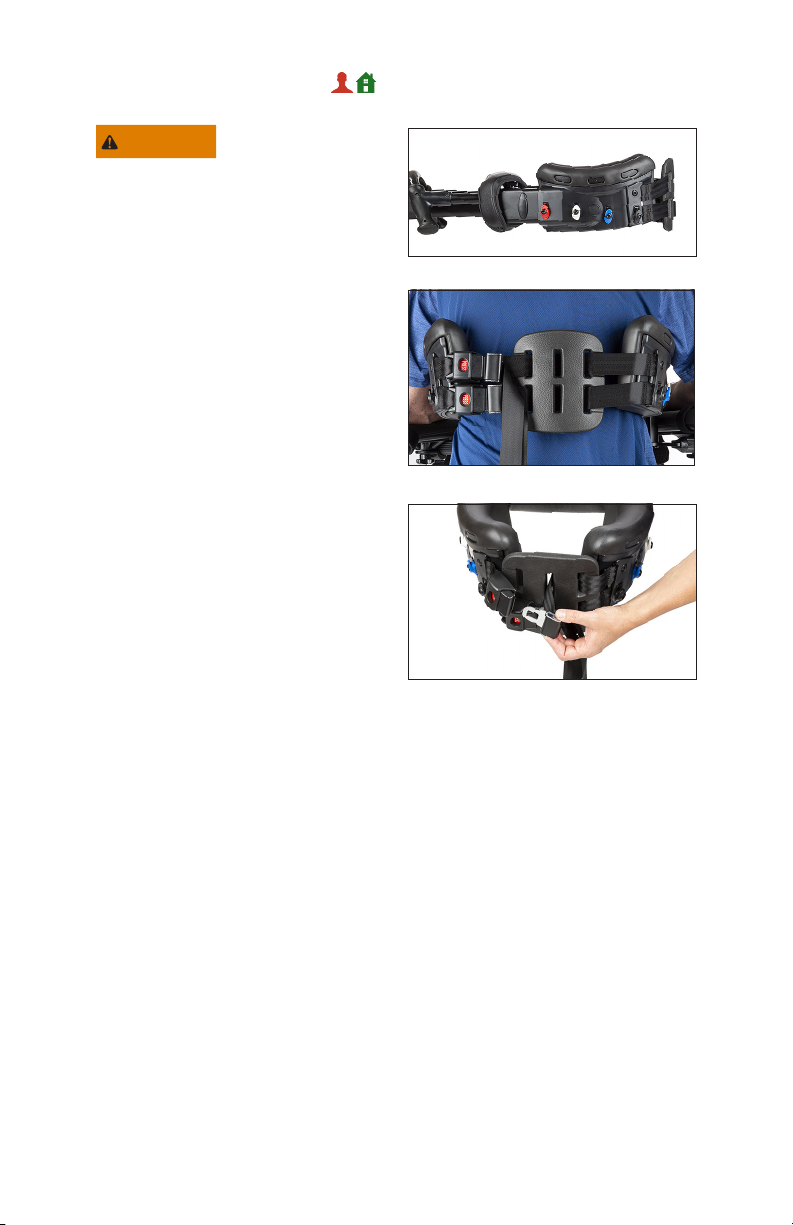
○The E-Pacer is equipped with two non-removable back belts with safety buckles.
Always ensure that the back belts are in place and that the release tabs on all buckles
are fully latched before initiating a lift or transfer.
○When the E-Pacer is used in the posterior configuration, with the client facing
rearward in the device, the client can access the back belt safety buckles. The E-Pacer
should not be used in the posterior configuration with clients of unreliable judgment
who may unintentionally release the safety buckles while supported by the device. The
caregiver must assess whether posterior use is appropriate for an individual client.
WARNING

4
IMPORTANT
Please save this product manual for future reference. Additional copies are
available at http://www.rifton.com/customer-service/product-manuals.
○For safe use of the E-Pacer, prior to initiating a transfer, move the origin and
destination of the transfer as close to each other as possible. For example: a client
who is to be transferred from a wheelchair to a toilet should be wheeled close to the
toilet prior to lifting to minimize time spent in transfer. Never use the E-Pacer for long
distance transport of a lifted client.
• Using straps, trays, or supports to restrict a client’s movement is considered behavioral
restraint. Rifton products are not intended for this use.
• This product is intended for indoor use only and must not be used in or around water
other than for bathing and shower transfers in accordance with instructions provided.
• To avoid pinching or crushing:
○Ensure that all hands and feet are clear of the vertical lifting column before activating
the up/down switch.
○Ensure that all hands and feet are clear of the base frame expansion system and the
base legs before expanding or retracting the base.
• To prevent head and neck injury, never use the E-Pacer to lift a client within a vertically
confined space such as inside a vehicle; always check that adequate head clearance
exists before initiating a lift or transfer.
• Never use a broken or damaged E-Pacer. Regular maintenance in accordance with this
manual is necessary for safe use of the E-Pacer.
WARNING
Key for users
Use this key to determine which sections of this product manual apply to you.
Technical Users For professionals who order and set up Rifton products.
Home Users For care-givers who use Rifton products on a regular basis.
Maintenance Personnel For anyone who is responsible for service or
re-ordering of Rifton products and parts.

5
Recommended use
The E-Pacer is a Class 1 medical device. It is a mobility and transfer device. As a mobility
device it helps a caregiver raise a client to a standing position, and then provides support
for standing or ambulation. For transfers it enables a qualified caregiver to lift a client in
the seated posture and transfer the client between wheelchairs, chairs, toilets, beds or
therapy tables.
User and item dimensions
User dimensions – inches (cm)
Key user dimension: Girth
Girth: 22 – 55 (56 – 140)
Important: User’s weight and height must not exceed:
maximum height: 77 (196), maximum weight: 350 lbs (160 kg)
Key dimensions – inches (cm) K660 E-Pacer
E-Pacer overall length 44 ¾ (113.5)
E-Pacer overall width 31 ½ –51 ¾ (80 –131.5)
E-Pacer overall height 32 ¾ min. – 59 max.
(83.5 –150)
E-Pacer weight – lbs (kg) 72 (32.5)
Turning diameter 50 (127)
Floor to top of base leg 8 ¾ (22.5)
Min. user armpit height (when standing or ambulating) 31 ½ (80)
Max. user height (when standing or ambulating) 77 (196)
Max. working load – lbs (kg) 350 (160)

6
Check your order
Please check that your E-Pacer has been outfitted as you ordered it. Every E-Pacer comes
with a battery and a battery charger.
All components are retrofittable with the exception of the scale, which must be ordered at
the time of purchase. Please follow the instructions included in this manual to ensure that
your E-Pacer is assembled and used correctly.
If your shipment is incomplete or in any way damaged on arrival,
please call customer service, 800.571.8198.
Basic item
Scale (optional)
Body support
system
Control box
with built-in
Up/down
switch
Expansion
handle
Base legs
Vertical
lifting
column
Electronic actuator

7
To avoid injury, never
operate the E-Pacer
without the back belts in place. Always
ensure that the buckles are fully latched
before initiating a lift or transfer.
Figure 7a: The E-Pacer’s body support
system includes the body support pads,
patient hand grips, ring clips, and the back
belts, buckles and back pad.
Figure 7b: The back belts have a single
point release with a safety cover over
the buckle buttons to prevent accidental
release. The straps are woven through a
padded back pad, which spaces the straps
apart and adds support and comfort for
the user.
Figure 7c: For smaller users, the straps
can be threaded through the middle slots
as shown, or the pad can be removed
completely.
The following can also be attached to the
body support system, depending on how
the E-Pacer is to be used:
• Thigh straps (see figure 16a, and pp.
23 – 24 for use)
• Pelvic support (see figure 16b and 16c,
and p. 25 for use)
• Hip positioner (see figure 16d)
• Arm prompts (see pp. 17 – 18)
• Arm platforms (see p. 19)
Figure 7a
Figure 7b
Body support system
WARNING
Figure 7c

8
WARNING
Control box
To prevent inadvertent
operation of the
up/down switch when the E-Pacer is not
in use, press the E-Stop button (A) to
disconnect the battery.
Figure 8a: The control box houses the
microprocessor and rechargeable battery
which power and control the E-Pacer’s
electric actuator. Up/down arrows (B)
on the control box control the E-Pacer’s
vertical movement.
Figure 8b: To insert the battery, slide it
into the control box, then push the battery
back until it clicks into place. To remove
it, squeeze the lever on the back and lift
it out.
To prevent long-term
battery damage, remove
the battery from the control box and place
it in the charger every night, even if the
battery level indicator is still green.
Battery level indicator
To prevent injury:
• Charge or change the battery
immediately if the battery level light
turns red; do not attempt further lifts
or transfers with a red light.
• Prior to every use of the E-Pacer,
activate the up/down button to turn on
the battery level light, and verify that
the light is green. If it is not, change or
charge the battery.
Figure 8c: The battery level light indicates
the charge remaining in the battery. A
green light means the charge level is
adequate for use, yellow indicates that the
battery should be charged soon, and red
indicates a very low charge. An audible
beep indicates that the battery is entirely
depleted. A fully charged battery will give
approximately 70 complete lift cycles.
NOTICE
Figure 8a
Figure 8b
Figure 8c
CAUTION
AA
BB

9
To prevent damage to the
battery, charge it when
the light turns yellow. The indicator light
will extinguish 10 minutes after the last
activation of the up/down switch. It will
turn on again if the up/down switch is used
or if a battery is inserted into the control
box.
If the battery level becomes critically low,
indicated by the battery level light turning
red, the microprocessor will disable the
up/down switch. However, the emergency
lowering button will continue to function.
The emergency lowering button will continue
to function even if the battery level has
dropped below the threshold for operation
of the up/down switch. It overrides all other
inputs.
To prevent injury, all
caregivers should
become familiar with the location and
operation of the emergency stop button
and the emergency lowering button
before using the E-Pacer.
Emergency stop button
Figure 9a: To stop the E-Pacer motor in the
event of an emergency, press the round
red emergency stop button located on the
front of the control box. Twist it clockwise
to reset it.
Emergency lowering button
Figure 9b: The emergency lowering button
(A), located on the front of the control box,
provides a means of lowering the body
support if the up/down switch fails.
Press the emergency lowering button to
lower the body support as required.
NOTICE
CAUTION
Figure 9a
Figure 9b
AA

10
Base frame
expansion system
To avoid injury, ensure
that all hands and feet
are clear of the expansion handle and the
base legs before expanding or retracting
the base.
Figure 10a: The base frame expansion
system adjusts the width of the base frame
from 31 ½ –51 ¾ (80 –131½ cm). It expands
so that clients can be lifted from wide
chairs and wheelchairs, and retracts for
maneuverability, and to enable the E-Pacer
to pass through narrow doorways.
Swing the expansion handle to the right to
expand the frame, and to the left to close it.
WARNING
Figure 10a
Tip: Disengage direction locks prior to
moving the expansion handle.

11
Casters
Adjustments
Figure 11a:
Swivel lock (A) prevents the caster from
swiveling.
• To engage the swivel lock: press
button (A).
• To disengage, press button (B).
Locking all four casters will keep the client
traveling in a straight line.
Locking the rear casters (those behind the
client) will help stabilize the client, while
still allowing for turning.
To engage caster brake (C), press lower
part of brake pedal. To release the brake,
press upper part of brake pedal.
To engage caster drag rotate dial (D).
Directional lock (E) allows the caster to
turn in one direction only, helpful for clients
who may involuntarily roll backward while
trying to walk. To engage the directional
lock:
• Push lever down until it snaps into place.
• When the directional lock is engaged,
the caster or wheel will make a clicking
noise while moving forward, and lock
when pushed backward.
Figure 11a
AA
BB
CC
DD
EE

12
Components
Front handle
To prevent pinching or
crushing, ensure that
all hands and feet are clear of the vertical
lifting column before activating the up/
down switch.
Figure 12a: The front handle enables a
caregiver to maneuver the E-Pacer. It
includes the up/down switch (A), located
on top of the right hand-grip, which adjusts
the height of the body support. Push the
rocker switch up to raise the body support
and down to lower it.
Attaching
The front handle is removed for shipping
and must be attached to the E-Pacer frame
with four bolts:
1. Figure 12b: With the Allen wrench
found in the accessory carton, remove
the four bolts from the cover plate and
take it off.
2. Figure 12c: Hold the front handle
against the attachment point as shown,
insert the bolts in the holes, and tighten
them snugly with the Allen wrench,
starting with the top bolts.
3. Figure 12d: Insert the electrical jack
plug into its receptacle on the actuator
control box. The release tab on the plug
must be facing towards you.
WARNING
Figure 12a
Figure 12b
Figure 12c
Figure 12d
AA

13
Scale
Figure 13a: The scale has two purposes: it
can be used to measure a client’s weight,
and to measure the weight a client is
bearing during ambulation.
To use the scale, turn on the display and
use the lb/kg button to display either
pounds or kilograms. Before approaching
the client who will be weighed, attach
all the components you will need for this
particular client, (leg straps, arm supports,
etc.) and then press the ZERO button to
zero the scale. Proceed to lift the client.
Once a client is completely supported by
the E-Pacer, the client’s weight will be
displayed.
There are two ways to measure
weight-bearing during ambulation:
Method 1: Turn on and zero the scale
as previously described. Once the client
is lifted and in the walking position, the
weight displayed is the amount of weight
that the E-Pacer is bearing.
Method 2: Using the thigh supports and
the seated transfer procedure, lift the client
with the E-Pacer. With the client’s full
weight displayed on the scale, press the
zero button. Next, re-position the client
for ambulation. The weight the client is
bearing will be displayed as a negative
number.
Figure 13b: To replace the scale batteries,
push outward on the small tab at the rear
of the scale housing and lift the battery
cover (a small, flat head screwdriver
inserted into the slot at the back of the
lid may be used to gently pry it up). Insert
fresh AA Alkaline batteries; the cells must
be oriented as shown by the inscription in
each battery receptacle.
Figure 13a
Figure 13b

14
Scale Information
• To obtain an accurate weight measurement, the client must be lifted clear of all weight-
bearing surfaces, and the feet or legs must not be in contact with the base frame of the
E-Pacer.
• The scale uses four AA Alkaline batteries. The battery life is approximately 100 hours of
continuous use, or approximately 500 weight recordings.
• The scale will automatically turn off if it does not sense a change in weight for more than
10 minutes.
• The scale is accurate to one percent if used correctly.
• Rifton recommends that the scale be calibrated by a qualified technician at three to
five year intervals, depending on frequency of use. For instructions on service and
calibration, please contact Rifton customer service.

15
Gait Tracker
The Gait Tracker app allows data from
the E-Pacer scale to be displayed on
mobile phones and tablets via a BlueTooth
connection. The app has two primary
functions.
1. It displays the weight measured by
the scale, averaged over a 10 second
interval for smoothness.
2. Figure 15a: It calculates the average
weight on the E-Pacer over the course
of a gait training session. This value can
be used to record and track a client’s
weight bearing capability over time.
To use the Gait Tracker app:
Figures 15b and 15c:
1. Install the app on your phone or tablet.
2. Activate Bluetooth on the scale by
pressing the “BT” button (A).
3. Open the Gait Tracker app on your
mobile device. Your device will pair with
the scale when you open the app.
4. Press “start” on the app when you are
ready to begin the gait training session.
5. Use the “pause” and “resume”
commands as needed until the session
is over.
6. Before pressing the “reset” button
at the end of the session, be sure to
make an external record of the session
average if needed for tracking purposes.
Pressing “reset” will clear all stored data
from the app.
Figure 15d: To provide a client with access
to the scale data, a phone may also be
mounted on the client handlebar using a
phone mount for a bicycle handlebar.
Figure 15a
Figure 15b
Figure 15c
AA
Figure 15d

16
Thigh straps
Figure 16a: Thigh straps are used to make
seated transfers. Choose either narrow
(5”) or wide (7”), depending on the needs
of your client. Additional straps can be
purchased for individual clients.
Pelvic support
Figure 16b: The pelvic support is used
for sit-to-stand transfers and supported
ambulation. It is attached by hooking the
rings to the color-coded clips of the body
support system.
Figure 16c: Note that the pelvic support
may fit best when the straps are crossed.
Hip positioner
Figure 16d: The hip positioner is used to
encourage optimum pelvic positioning
during gait training. It has an optional pad
for comfort. It is attached by hooking the
back rings onto the grey clips of the body
support system and the front rings onto
two of the remaining four clips (including
the yellow ones in the front). Adjust the
four straps for further positioning.
Odometer
Figure 16e: The odometer displays
distance traveled. To reset display to 0,
press button (A). To display total lifetime
distance traveled, press and hold button
(A) for one second. Lifetime distance will
be displayed in kilometers or thousands of
feet, depending on unit setting.
To switch between feet or meters, press
and hold button (A) until units change
(approximately 10 seconds).
Figure 16e
Figure 16a
Figure 16b
Figure 16d
AA
Figure 16c

17
Figure 17a
Figure 17b
Figure 17c
Arm prompts
Figure 17a: Arm prompts provide
positioning support for clients who
have low muscle tone. Arm prompts
adjust in many directions and angles
to accommodate different positioning
requirements.
If arm prompts were purchased initially
with the E-Pacer they will be attached
and ready for use. If they were purchased
separately, mounting brackets must be
installed onto the body support.
Attaching arm prompts and
mounting brackets:
• Figure 17b: Remove the plastic hole
cover (A) from the body support channel
by unscrewing wing knob (B) inside the
channel.
• Figure 17c: Install the mounting bracket
(C) on the body support channel with
the large, lipped end up.
• Securely tighten the attachment knob
(D) on the threaded stud, which will now
be protruding inside the body support
channel.
• Figure 17d: Install the mounting arm by
pressing the red adjustment button (E)
and sliding it over the mounting bracket
from the top or bottom
Figure 17d
AA
BB
CC
DD
EE
Tip: Arm supports generally give the
most lifting support when adjusted with
the client’s elbow directly below the
shoulder.

18
Adjustments
Figure 18a:
Height adjustment
Press button (A) and slide the post to the
desired height.
Loosen knob (B) to:
• Slide the arm pad toward or away from
the user.
• Rotate up or down.
• Rotate in or out.
• Move the arm pad backward or forward.
To adjust the handgrip:
1. Loosen knob (C).
2. Slide the handgrip (F) forward or back to
match the client’s forearm length.
3. Rotate the handgrip from side to side.
Arm strap (D) and wrist strap (E) are
used to secure the client’s arm in the
arm prompt.
To remove the mounting brackets:
1. Figure 18b: Unscrew the attachment
knob (G) located inside the body support
channel. Remove the arm prompt
mounting bracket (H).
2. Figure 18c: Install the oval shaped hole
cover (I) (found in accessory carton) by
inserting the threaded stud through
center hole and tightening the wing
knob (J) inside the body support channel
onto the stud.
Figure 18a
AA
BB
DD
Figure 18b
Figure 18c
FF
GG
HH
II
JJ
EE
CC

19
Figure 19b
33
11
22
BB
Arm platforms
Attaching/detaching see pp 17-18
Adjustments
Height adjustment:
Figure 19a: Press the red button (A) and
slide the post to the desired height.
Figure 19b:
Loosen knob (B) to:
1. Tilt for forward or backward slant.
2. Rotate horizontally.
3. Slide the arm platform toward or away
from the client along the post.
To move the arm platform between
backward and forward positions:
• Loosen knob (B).
• Remove the arm platform pad from
the post.
• Spin the ratchet mechanism 180˚ so that
the sleeve is in the opposite position.
• Remount the arm platform pad to
the post.
Figure 19a: The arm straps (C) and wrist
strap (D) secure the client’s arm in the arm
platform. They can be removed completely,
if desired; unfasten the strap and pull it out
of the slot beneath the platform.
To adjust the optional handgrip:
1. Loosen knob (E).
2. Slide handgrip forward or back for
different forearm lengths, or rotate the it
from side to side. The arm straps (C) and
wrist strap (D) secure the client’s arm in
the arm platform.
Figure 19a
AA
EE
BB
CCDD
Tip: Arm supports generally give the
most lifting support when adjusted with
the client’s elbow directly below the
shoulder.

20
Switch pole
To prevent serious
injury, a qualified
caregiver must determine whether it is
safe to place the up/down switch within
reach of the client. Do not use the switch
pole with clients of unreliable judgment.
The switch pole is designed to place the up/
down switch within reach of a client in the
E-Pacer, enabling either the client or the
caregiver to adjust the height of the body
support. To attach it:
1. Feed the wire through the mounting
bracket on the control box.
2. Insert the switch pole into the mounting
bracket, facing it either forwards or
backwards.
3. Figure 20a: Plug the cord into the
receptacle at the bottom of the control
box.
Adjustments (Figure 20b)
1. To change the orientation of the switch,
lift the switch pole out of the mounting
bracket and rotate it 180°.
2. Re-insert the switch pole into the
bracket.
WARNING
Figure 20a
Figure 20b
Other manuals for E-Pacer K660
1
Table of contents
Other Rifton Mobility Aid manuals

Rifton
Rifton E420 User manual

Rifton
Rifton Stander S410 User manual

Rifton
Rifton Stander S410 User manual

Rifton
Rifton K589 User manual

Rifton
Rifton K310 TRAM User manual

Rifton
Rifton Stander Size 2 User manual

Rifton
Rifton Blue Wave E541 User manual

Rifton
Rifton R123 User manual

Rifton
Rifton Blue Wave E806 User manual

Rifton
Rifton Pacer K640 large User manual