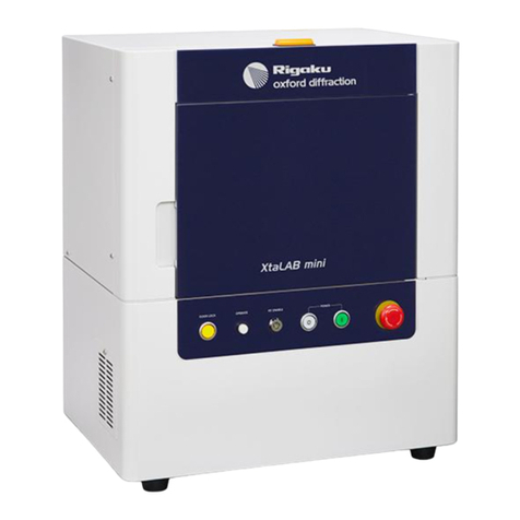
Rigaku MiniFlex 600 User manual

Benchtop X-
ray Diffractometer
Instruction Manual
This image is an example of MiniFlex series. The actual product may differ from the image.

This manual describes the correct use of the product as well the usage precautions to be observed. To
obtain full-expected performance from the product, thoroughly read this manual.
Also, store this manual at an easily accessible place so that you can promptly refer to it whenever
it is necessary.
The contents of this manual are subject to change without prior notice.
This manual described in it may not be disclosed to a third party or copied, in whole or in part, without
the written consent of Rigaku Corporation.
In no event will Rigaku Corporation be responsible for the results of the use of this manual.
As a rule, one set of the instruction manual has to be purchased for each product.
If there are any missing or incorrectly collated pages in the delivered instruction manual, please
contact the sales representative who you purchased the instrument from for instruction manual
replacement.
Windows is a registered trademark of Microsoft Corporation in the United States and other countries.
The ® marks have been omitted.
Adobe, the Adobe logo, and Reader are either registered trademarks or trademarks of Adobe Systems
Incorporated in the United States and/or other countries. The ™ and ® marks have been omitted.
The names of actual companies and products mentioned herein may be the registered trademarks or
trademarks of their respective owners.

MiniFlex 600: Benchtop X-ray Diffractometer i
Contents
Overview .............................................................................................................1
Overview of MiniFlex 600........................................................................................... 1
Optical System using SC ........................................................................................... 2
Configuration ......................................................................................................3
Standard Configuration ............................................................................................... 3
Names of Parts......................................................................................................... 4
List of Shipped Items ................................................................................................ 8
Specifications.......................................................................................................9
X-Ray Generator ...................................................................................................... 9
Tube shield .............................................................................................................. 9
Goniometer (Angle measuring device) ........................................................................ 9
Detector (SC)......................................................................................................... 10
Counting control circuit (ECP)................................................................................. 10
Radiation enclosure ................................................................................................ 10
Cooling-Water Unit ................................................................................................ 10
X-ray tube ..............................................................................................................11
Computer (reference specifications)...........................................................................11
Standard Software ...................................................................................................11
Optional accessories ............................................................................................... 12
D/teX Ultra High-speed 1D Detector (Optional)......................................................... 12
Installation Condition ........................................................................................13
Installation Room ................................................................................................... 13
Environmental Conditions of Installation Room ......................................................... 13
Preparing Power Supply.......................................................................................... 14
Cooling water ........................................................................................................ 15
Drainage ............................................................................................................... 15
Others ................................................................................................................... 15
Installation of MiniFlex600 ................................................................................17
Unpacking............................................................................................................. 17
Installing the X-Ray tube......................................................................................... 17
Connecting the Cooling Water Hose ......................................................................... 18
Installing the Scintillation Counter (SC) .................................................................... 19
Installing the D/teX Ultra (Optional)......................................................................... 22
Installing the Beam Stop ......................................................................................... 24
Installing and retracting the variable knife edge.......................................................... 24
Installing the variable knife edge ....................................................................... 24
Retracting the slider ......................................................................................... 26

ii MiniFlex 600: Benchtop X-ray Diffractometer
Installing the DS and IHS (Length limiting)............................................................... 27
Connecting the power cable..................................................................................... 27
Connecting with Computer...................................................................................... 27
Installing the Software ............................................................................................ 28
Setting and Adjustment...................................................................................... 29
Types of Soller Slit, Confirming the Soller Slit........................................................... 29
Types of incident Soller slit............................................................................... 29
Confirming the incident Soller slit ..................................................................... 29
Types of receiving Soller slit............................................................................. 30
Optics Alignment (Required for Periodic Inspection or Installing X-Ray Tube).............. 31
Optics alignment (for SC)................................................................................. 31
Optics alignment (D/teX Ultra) ......................................................................... 42
Optics alignment (for D/teX only) ..................................................................... 50
HV/PHA Adjustment of Scintillation Counter (SC)..................................................... 64
Discriminator Value Setting by D/teX Ultra............................................................... 67
Automatic adjustment of discriminator value ...................................................... 67
Directly entering the D/teX Ultra adjustment value.............................................. 69
Initial Setting of the Measurement Environment (Required When the X-Ray Tube Type Has
Been Changed)....................................................................................................... 71
Data Measurement and Setting Procedure for Real-Time 2 theta Axis Correction (Required
for Initial Setup or Periodic Inspection)..................................................................... 72
Startup and Shutdown (Daily routine)................................................................77
Starting Up the System............................................................................................ 77
Shutting Down the System ...................................................................................... 78
Measurement of Samples (Daily routine) ............................................................79
Preparing the Sample Plate ...................................................................................... 79
Preparation of powder sample on aluminum sample plate ..................................... 79
Preparation of block sample on aluminum sample plate........................................ 81
Preparation of powder sample on glass sample plate ............................................ 81
Cleaning spilled or deposited powder sample ...................................................... 82
Slit system............................................................................................................. 83
Slit Correction........................................................................................................ 83
Measurement with MiniFlex Guidance...................................................................... 85
Maintenance ......................................................................................................91
X-Ray Tube and Scintillation Counter (SC) ............................................................... 91
Replacing the X-ray Tube (Procedures required when cleaning filter or replacing tube) 91
Removing and installing the X-Ray tube ............................................................ 91
Disassembling the X-ray tube and cleaning the filter............................................ 93
Cleaning and Further Information............................................................................. 94
Confirming the Alarm Information ........................................................................... 95

MiniFlex 600: Benchtop X-ray Diffractometer iii
Installing the Optional Sample Attachment ........................................................97
Installing the Counter Monochromator (Optional) .............................................99
Installing the Counter Monochromator.................................................................... 100
Optics alignment and notes on monochromator ........................................................ 103
Arrangement of slits ............................................................................................. 104
Item No. 2005L101 / L102 / L201 / L202 / L301 / L302 / L401 / L402
Manual No. ME14992A03
2014. 02 (3rd Edition)


MiniFlex 600: Benchtop X-ray Diffractometer 1
Overview
Before starting to use the MiniFlex 600 Benchtop X-ray Diffractometer (hereon
called MiniFlex 600), be sure to read this instruction manual thoroughly. Also, be
sure to read the "Guidelines for safe use of the Benchtop X-ray Diffractometer"
(ME11594*).
Overview of MiniFlex 600
The MiniFlex 600 is a successor of the MiniFlex Benchtop X-ray Diffractometer
(XRD) series. The MiniFlex 600 significantly improved its basic performance
while maintaining the compact size of MiniFlex series products.
Characteristics of MiniFlex 600
・By incorporating the real-time angle correction system, compact and wide-area
scintillation counter (hereafter called SC) which is equivalent to intensity of
150%, counter monochromator (optional) and other features, MiniFlex 600 has
significantly enhanced its basic specifications as a powder XRD system in terms
of angle accuracy, intensity and P/B ratio. Thus, a high quality data can be
obtained from a XRD system completed in a compact enclosure.
・An X-ray generator of 600 W (40 kV - 15 mA) enables 1.3 times higher output
than the existing model.
・The system is a location-free tool that can readily be transported and installed in a
relatively small indoor or outdoor space.
Optional accessories to enable good quality high speed measurements
・The MiniFlex 600 can be used for a variety of applications; starting from
diffraction pattern comparison of polycrystalline materials (such as powder
samples and metal plates) and up to qualitative & quantitative analyses as well as
quality control management of raw materials and products. Optional softwares*
for these purposes are available.
・Optional sample attachments, such as sample rotation attachment*, sample
changer*, and general atmosphere separator* can be used to improve quantitative
measurement accuracy or to automate the measurement.
・The counter monochromator* cuts X-rays (fluorescence X-rays, etc.) other than
the characteristic X rays (CuKα) used for the analysis. When the counter
monochromator is used, the data with low background and high P/B ratio can be
obtained.
・By replacing the SC with D/teX Ultra high-speed 1D detector*, a measurement
with 100 times higher intensity than SC, under the same slit conditions, is
enabled.
Items with * are optional.

Overview
2MiniFlex 600: Benchtop X-ray Diffractometer
Optical System using SC
Fig. 1.1 outlines the optical system of MiniFlex 600 using the scintillation counter.
This optical system adopts focusing geometry used in powder XRD generally and
irradiates the sample with divergent X-rays limited by a divergent slit. The features
of this geometry are the high diffracted X-ray intensity, which is provided by
diffracted rays from the sample concentrating on the RS (Receiving slit), and
high-resolution analysis patterns.
An X-ray beam from the X-ray tube (focal point F) is emitted in the direction 6 °
below the horizontal direction. With respect to this incident beam, the sample is
rotated by θ and the detector by 2θ. The diffraction pattern is obtained by rotating
2θ /θ repeatedly and measuring the diffracted rays from the sample.
A counter monochromator is available as an optional accessory. This accessory is
placed behind the RS (further side from the sample) shown in Fig. 1.1. The counter
monochromator cuts not only the Kβrays but also fluorescent X-rays and
continuous X-rays, which have an adverse effect for detecting micro peaks, thus
lowers the background and offers data with a higher P/B ratio. (Refer to “Installing
the Counter Monochromator (Optional)”).
Although omitted in Fig. 1.1, an auxiliary variable DS (Divergence slit) is placed
between the DS and Soller slit. This auxiliary slit helps to achieve the DS width of
0.1 mm at the time of optical axis adjustment. It also limits the radiation width to
"sample width + α" to prevent the irradiated area to spread outside the sample
without limit, thus improves the P/B ratio at low angles. The slit functions in the
background, and there is no need to concern about it on a daily basis.
DS (Divergence slit) is a slit to determine the width of the irradiation. Width of
1.25° and 0.625° are available. The 0.625°DS slit is used for measuring a sample
whose main peaks concentrate at low angles (2θ < 20°), such as organic sample.
For the RS (Receiving slit), the 0.3 mm RS is available. SS (Scattering slit) is a slit
to cut the scattered radiation from outside of the sample. Usually, the SS with the
same receiving angle as DS is used.
The Soller slits on the incidence and receiving sides limit the diffracted rays to
spread out in vertical direction (the top and bottom direction of this manual is the
vertical direction in the figure), thereby preventing the peak resolution from
decreasing.
Fig. 1.1 Outline of the optical geometry

MiniFlex 600: Benchtop X-ray Diffractometer 3
Configuration
Standard Configuration
X-ray generator (XG): Power source for X-ray generation
Tube shield: X-ray tube holder
Goniometer: Measurement unit at 2θdiffraction angle
Detector (SC): Scintillation counter
Counting control circuit (ECP): Counting and measurement controller
Radiation enclosure: Enclosure cabinet of the main unit that
provides protection from radiation
Flow rate detector: For monitoring flow rate of cooling water.
X-ray tube
LAN cable
Computer (for Japanese market only):
PC, Printer
An X-ray tube and a computer (PC, etc.) are required to use this equipment.
These components may be required to be prepared by the user or distributor due
to warranty issues.
If an auto-transformer or an external heat exchanger is required, contact the sales
representative who you purchased the instrument from.

Configuration
4MiniFlex 600: Benchtop X-ray Diffractometer
Names of Parts
(a) MiniFlex600 main unit
(b) Block diagram
Fig. 2.1 Appearance and block diagram of MiniFlex 600 (including optional components)
Heat
exchanger
Scan
HV
Detector(SC)
Sample
Water
cooling
Data output
2θ
X-ray
X-ray tube
Electronic
circuit panel
(ECP)
Angle control
Goniometer
Cable
High voltage
generator
Computer
X-ray generator

Names of Parts
MiniFlex 600: Benchtop X-ray Diffractometer 5
Fig. 2.2 Appearance of main unit and names of parts
Front view Right side view Rear view
Power ON/OFF switch
(〇
: OFF , |: ON)
Sample
chamber door
LAN cable outport
Door knob
X-Ray warning lamp
Power circuit breaker
Air vent
Emergency off switch
(EMO)
Power source
(inside)
Door Lock button
OPERATE lamp
Key hole of HV ENABLE key
Cooling water
IN/OUT
LAN connector
(inside)
Power cable
connector

Configuration
6MiniFlex 600: Benchtop X-ray Diffractometer
Front view (perspective drawing)
Fig. 2.3 Major components and names of parts
Top view (perspective drawing)
Control driver
Beam stop
(partition to prevent leakage)
X-ray tube
Tube shield
X-ray shutter
Goniometer
Detector (SC)
+ monochromator

Names of Parts
MiniFlex 600: Benchtop X-ray Diffractometer 7
Fig. 2.4 Dimensions of main unit (weight: approx. 80 kg)

Configuration
8MiniFlex 600: Benchtop X-ray Diffractometer
List of Shipped Items
Tabl e 2.1
Classific
ation
No.
Classificat
ion Name
Sub
Classifica
tion No.
Product Name Q’ty Note
1 Main
Body
1-1
1-2
1-3
1-4
1-5
1-6
1-7
1-8
MiniFlex 600 main unit
Scintillation counter (SC)
Standard sample holder
Receiving slit box
LAN cable
X-ray tube
Computer
Power cable (AC125V)
1
1
1
1
1
1
1
1
Incorporated in main unit
(only for Japan)*
(only for Japan)*
(only for Japan)*
2 Accessori
es in the
Storage
Box
2-1
2-2
2-3
2-4
2-5
2-6
2-7
2-8
2-9
2-10
2-11
2-12
2-13
2-14
2-15
2-16
2-17
2-18
Box
Aluminum sample plate
Glass sample plate, 0.2 mm deep
Glass sample plate, 0.5 mm deep
Setting jig (with Si sample)
Rectangular glass plate
Hex wrench
Cu absorber (0.3 mm)
Al absorber (0.2 mm)
DS: 0.625°
DS: 1.25°
SS: 1.25°
RS: 0.3 mm
IHS: 10-mm length limiting slit
Styrol plastic case
O-ring P-8
Si Powder
Ni filter
1
5
2
2
1
1
3
3
3
1
1
1
1
1
1
4
1
1
For tube shield vertical adjustment
For receiving powder sample spills
For tube shield
Angle Standard NIST SRM-640d
Standard thickness (0.015 mm)
3 Other
accessories
3-1
3-2
3-3
Cooling water hose
Cooling water hose band
Fixing jig for breaker OFF
10 m
2
1 set
Tetron braided PVC
Inner diameter 9 mm x Outer
diameter 15 mm
* For countries outside of Japan, these items may be required to be prepared by
the user or distributor.

MiniFlex 600: Benchtop X-ray Diffractometer 9
Specifications
X-Ray Generator
Tube output voltage: 20 to 40 kV (1 kV step)
Tube output current: 2 to 15 mA (1 mA step)
High-voltage generation method:
High-frequency Cockcroft-Walton method
Stability: Within ±0.05% for both the tube voltage and tube
current, with reference to ±10% of input power
variation
Tube shield
Applicable X-ray tube: Toshiba A-21, A-41, PANalytical PW22XX, etc.
Focusing-position adjustment mechanism:
±1 mm, continuously variable through the use of a
spring plate
X-ray shutter: Mechanical rotary shutter
Kβfilter: Ni-filter (for Cu-tube, standard thickness 0.015
mm). Other filters are optional.
Goniometer (Angle measuring device)
Type: Vertical θ/2θ
Goniometer radius: 150 mm
Scanning axis: θ/2θ linked
2θ scanning range: −3° to +145°
2θ measurement range: +2° to +145°
θ/2θ axis minimum step angle:
0.005° (2θ)
Positioning speed: 500° / min (2θ)
Scanning speed: 0.01 to 100° / min.
Datum angle: 2θ = 10°
Slit:
DS 1.25°, 0.625°
IHS (length limiting) 10 mm, 5 mm (optional), 2 mm (optional)
Auxiliary DS This is a variable slit to limit the width of X-ray
beam irradiated on sample to be approx. 20 mm
(sample width) at low angle area
SS 1.25°, 0.625° (optional), 4.2° (optional)

Specifications
10 MiniFlex 600: Benchtop X-ray Diffractometer
RS 0.3 mm, 0.15 mm (optional)
Incident side Soller slit
Soller (inc) = 5° or 2.5° *1
Receiving side Soller slit
Soller (rec) = 5° or 2.5° *1, 0.5° (optional)
*1Select either the standard type (incident receiving 5°) or the high
resolution type (incident receiving 2.5°). The incident side soller slit
cannot be changed by users. (Refer to “Types of Soller Slit, Confirming
the Soller Slit”)
X-ray take-off angle: 6°, fixed
Detector (SC)
Scintillator: NaI (T1)
Window material: Be
Effective window diameter: 23 mm
Dimension: 80 mm (L)
Counting control circuit (ECP)
θ/2θ axis minimum step angle: 0.01° (2θ)
SC high-voltage power source: 0 to 1000 V
Wave height discriminator circuit: Fixed pulse height system
Scaler: 32-bit counter
Radiation enclosure
Enclosure cover: Iron cover (with front door)
Front door: with interlock mechanism
Upper cover: with safety sensor
Warning lamp: lights on when X-ray generation is ON
Cooling-Water Unit
Flow rate meter: A flow rate of 3.0 l/min. or less on the
water-drainage side is detected.
Cooling water hose: φ9 inner diameter, φ15 outer diameter, 10 m in
length each (Tetron braided.)
Two cooling water hose bands are included.

X-ray tube
MiniFlex 600: Benchtop X-ray Diffractometer 11
X-ray tube
X-ray tube: Cu target (Standard)
Fe, Cr and Co target X-ray tubes can also be
used (Mo target cannot be used).
Maximum output: 1 kW (maximum output with this system is 0.60
kW.)
Focus size: 1 x 10 mm
Computer (reference specifications)
To use this equipment, connect a PC (desktop or laptop) which meets all the
specifications described below, with Windows 7 Professional 32 bit version
installed.
Main unit
CPU: Intel Core i3 or later
OS: Windows 7 Professional 32 bit version
(Japanese or English version)
Main memory: 2 GB or more
Hard disk: 100 GB or more free space
Display: 1024 x 768 resolution or higher
CD-ROM drive: Required
Keyboard: Required
Mouse: Required
LAN port: One port
Printer
Ink-jet color printer (compatible with A4 size)
LAN cable
Standard Software
MiniFlex Guidance
PDXL Basic Software
Integrated Intensity Calculation

Specifications
12 MiniFlex 600: Benchtop X-ray Diffractometer
Optional accessories
Counter monochromator
D/teX Ultra High-speed 1D detector
Sample rotation attachment
6 sample changer ASC-6 AMII
General atmosphere separator (quick air-tight sample attachment)
Optional software
・PDXL software (Integrated Powder X-ray Diffraction Software)
・ICDD software
・ICDD database software (Qualitative analysis database)
・Environmental dust quantitative-analysis (SiO2, etc.) software
・Quantitative analysis software (quantitative analysis through the use of the
calibration-curve method and standard addition method)
D/teX Ultra High-speed 1D Detector (Optional)
Detection element: 1D semiconductor element
Window material: Be
Effective window size: 13 mm (W) × 20 mm(H)
Dimensions: 80 mm (L)
Included accessory: Beam stop
Variable knife edge
The following items are specifications that differ from SC:
2θ measurement range: +2° to +140°
Slit:
SS 8 mm (also called AS: Antiscatter slit)
ICDD:
International Center
for Diffraction Data

MiniFlex 600: Benchtop X-ray Diffractometer 13
Installation Condition
To install MiniFlex 600, the following conditions must be satisfied:
Installation Room
The MiniFlex 600 is a benchtop installation type equipment. Prepare a bench or
a desk with the space and load limit specified below, and install it on a stable
bench.
Dimensions and Weight of the Equipment
560 (W) x 460 (D) x 700 mm (H), weight: approx. 80 kg
・Additional space for a computer and printer is required.
・Do not place any object within 30 cm from the vent located on the right side
of MiniFlex 600.
Environmental Conditions of Installation Room
Vibration of floor: The floor must not have vibrations perceivable to
the human body.
Temperature: 15°C to 25°C
Relative humidity: Below 65% (no condensation)
Abrupt changes in temperature and relative
humidity adversely affects data measurement
accuracy, as well as the performance and service
life of the equipment.
Magnetic field: There must be no source of magnetic fields nearby
that may adversely affect the LCD display of the
computer.
Others:
・The room must be well-ventilated, without
direct sunlight or heat radiation from
high-temperature objects.
・The atmosphere must not contain inflammable
gases, corrosive gases, or salinity.
・The room must not be subject to the infiltration
of cotton dust, sand, soil dust, metallic dust, or
other dust.

Installation Condition
14 MiniFlex 600: Benchtop X-ray Diffractometer
Preparing Power Supply
To install MiniFlex 600, prepare a power-distribution board with a capacity
equal to or larger than the following ratings. If other devices are to be used in
combination with this diffractometer, the distribution board must have an
additional capacity to cover those devices’ power consumptions.
Power for MiniFlex600 main unit
Power requirements: 100 V to 240V AC±10%, 1-phase, 50/60 Hz
Power consumption: 10.0 A, 1.0 kVA
* Furnish a 15 A, grounded power outlet (3-contact).
* The standard included cable (only for Japan) is compatible up to 125 V AC.
For countries outside of Japan, it may be required to be prepared by the user
or distributor.
Power for computer
Power requirements: 100 V AC±10%, 1-phase, 50/60 Hz
Power consumption: 7.0 A, 0.7 kVA
* Furnish a 15 A, grounded power outlet (3-contact).
・Ensure that one wire of a single-phase system is grounded.
Grounding for a single-phase, two-wire line
・No surge/noise generating equipment must be connected to the wiring for
MiniFlex 600.
・Connect the power source and MiniFlex 600 main unit directly with a cable.
Do not insert a switch or any other power-consuming device in between.
Table of contents
Other Rigaku Measuring Instrument manuals
Popular Measuring Instrument manuals by other brands

Kingfisher
Kingfisher KI 3800 Series Quick reference guide

AEMC
AEMC MN114 user manual

Endress+Hauser
Endress+Hauser SpectraSensors J22 TDLAS operating instructions

Quantum Composers
Quantum Composers Autofocus AF910 specification

CROSSTEX
CROSSTEX Accutron Digital Ultra user manual

AVO
AVO AVOMETER 8 operating instructions