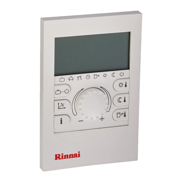
Rinnai BRIVIS Touch User manual

Touch Controller
Installation Manual
by

2
Touch Controller Kit
Scope
Please read these instructions carefully before installing this
product. This manual covers the installation of the wall mounted
Touch Controller for the following applications:
•Gas Ducted Heating
•Gas Ducted Heating & Refrigerated Cooling (Dual Comfort)
•Evaporative Cooling
•Zoning, including ZonePlus
For the installation of Heating and Cooling products please refer to
the equipment Installer Manuals.
This manual is based on Australian Standards - for all other
applications, please refer to relevant local codes and regulations.
Any deviations from these instructions may, at the discretion of the
company, void the warranty. As a result, the customer and/or
installer may be charged a fee for non-product warranty related
call outs. Also, note that failure to comply with these instructions
may preclude the company from being able to service the product.
Terminology:
Shall: Indicates a mandatory requirement of this manual.
Should: Indicates a recommended requirement of this manual.
Disclaimer
IMPORTANT NOTICE: This document is a guide only. Laws, regulations and industry standards can
vary between States and Territories. Accordingly, this guide must be read in conjunction with, and
subject to, all laws, regulations and industry standards applicable in the State or Territory in which the
products are installed. You must ensure that the installation of the products will comply with
those laws, regulations and standards, and that the products recommended to customers are
fit for the purpose for which they are intended.
Table 1: Touch Controller Kit Part No. B063047
Contents and Description
Qty
Touch Controller 1
Interface Module 1
Power Transformer 1
Power & Communication Loom 1
Plug & Screw Kit (for Touch) 1
Screw (for Interface Module)
2
Screw Driver 1
Inspect the product to ensure it matches your order. In the event of
damage or incorrect delivery, notify the supplier immediately. The
company accepts no responsibility for installation of damaged or
incorrect product.
Please read these installation instructions before undertaking the
installation process.
Specifications subject to change without notice. Pictures for illustration purposes only.
© Brivis Climate Systems Pty Ltd 2020
All rights reserved. No part of these documents may be used in any way or form without prior written
consent from Brivis Climate Systems Pty Ltd.
•The Touch Controller is compatible with selected units only.
For information on compatibility please contact your Dealer.
•Your Touch Controller is compatible with the Rinnai Touch App,
however they are independent items. An additional Wi-Fi accessory
must be installed and configured to enable Wi-Fi functionality.
•Pre-2010 compatible heaters will have limited on-board diagnostics.
3
Table of Contents
1.0 Home Screen – Key Functions ................................5
2.0 Touch Controller Installation .................................... 6
2.1 Location of the Touch Controller .............................6
2.2 Location of the Interface Module .............................7
2.3 Install the Touch Controller......................................7
2.5 Install Interface Module............................................8
2.6 Connection of Interface Module to P&C Loom ........ 9
2.7 Connection of Interface Module to Appliance........10
3.0 System Setup ........................................................10
3.1 Turning the System ON .........................................10
3.2 Set Day/Time .........................................................11
3.3 Installer Setup ........................................................12
3.4 Reset Networker ID ...............................................13
3.5 Networker Parameters...........................................14
3.6 Cooler Parameters.................................................14
3.7 Heater Parameters ................................................14
3.8 System with no Zones ...........................................14
3.9 System with Zones (Inc. ZonePlus).......................15
3.10 System Operation ................................................15
3.11 Service Notification Message ..............................15
3.12 Outdoor Temperature Sensor (Optional) .............16
4.0 Calibrating the Touch Controller ............................17
5.0 Product and Warranty Registration........................18
6.0 Instruct Home Owner on System Operation ..........18
7.0 Troubleshooting .....................................................18
7.1 Power Outages ......................................................18
7.0 Appendix ................................................................19
Mains electrical and other communication cables can
cause interference with system controls and low voltage
circuits and wiring.
Always observe guidelines and instructions for specific
products, and in general:
•Ensure correct wiring type and minimum gauge
is used.
•DO NOT exceed maximum specified lengths.
•Install a minimum distance of 40cm from all high
frequency cables and devices such as:
- 240V or 415V mains power cables
- Computer / data cables
- Broadcasting, TV antenna or Cable TV cables
- Communication / telephone cables
- High frequency cables within an appliance
(e.g. heater igniter cable)
Failure to observe these requirements may adversely
affect the performance and reliability of this appliance
and not be covered by warranty.

4
Definitions
Networker
Networker is a term used for a temperature sensing or
communicating device which communicates over two-wire bus.
There can be only one Master Networker (n01), all others must be
slaves (n02, n03, n10).
Touch Controller
Primary user interface with touchscreen display. Where multiple
Touch Controllers are installed, the “Master” Touch Controller can
be identified by the letter “M” displayed in the bottom right hand
corner of the screen. The Master has default sensor identification
“n01”.
The Touch Controller is a touchscreen thermostat which
communicates over two-wire bus. It is compatible with NC-3, NC-6
and NT-1 sensors.
NC-6 Networker Controller
A user interface with LCD display. The NC-6 has default sensor
identification “n01 ID00:1” (Master) and should be changed to a
slave if used on the same system as the Touch Controller.
NT-1 Remote Temperature Sensor
Zone temperature sensor with an LED that blinks during
communication with Master Touch Controller. Default NT-1 sensor
identification is “n02”. Additional Touch Controllers can be used in
place of up to 3x NT-1 sensors. The NT-1 sensor can also be
used as the outdoor temperature sensing device.
Zone
One room or a group of rooms; normally selected on the basis of
usage or that have similar heating or cooling needs.
Controlled Zone
A zone that is separately controlled by its own zone sensor and
zone damper. There are as many zone sensors in the home
comfort system as there are Controlled Zones.
Common Zone
A zone that is not separately controlled by its own sensor and zone
damper. It operates whenever heating or air conditioning is on,
regardless of the status of any controlled zones.
Constant Zone
A predetermined zone, typically the largest and containing the
return air grille, is designated as the Constant Zone. The Constant
Zone functions as a Common Zone only during refrigerated cooling
mode to ensure the minimum cooling airflow requirements are met.
Multi Temperature Set Point (MTSP) System
The zone temperature set point can be set independently across
all Touchscreens and/or Temperature Sensors.
Single Temperature Set Point (STSP) System
The zone temperature set point is the same across all
Touchscreens and/or Temperature Sensors.

5
1.0 Home Screen – Key Functions
Manual or Schedule
Operation
Diagram 2: Add-On Home Screen
* Active
with MTSP & STSP
systems only
Diagram 1: Heating Home Screen
Flame
Symbol
Power
Zones Where
Fitted *
Mode Indicator
Adjust Set
Temperature
Indoor
Temperature
Fan Status
Indicator
Day
Digital
Clock
M - Master
Controller
System Mode
(HEAT/COOL/EVAP)
Menu – Display
Options or Settings
Fan Select
Mode
Diagram 3:Evaporative Cooling Home Screen

6
2.0 Touch Controller Installation
The Touch Controller is connected to a compatible appliance
through the Interface Module. A 20m, four core, Power &
Communication Loom (P&C Loom), connects the Touch
Controller to the Interface Module.The Power Transformer
(12VDC) supplies power to the Interface Module.
Diagram 4: Connection Diagram
TW1
TW2
Power Transformer
12DC 1.5m loom
(supplied)
Appliance
(field supplied)
(field supplied
GPO)
Power & Communication
(Loom 20m supplied)
(0.75mm2figure -8 cable
field supplied)
Touch Contoller
(supplied)
Interface
Module
(supplied)
Isolation Switch
Weatherproof
enclosure for
external GPO
(field supplied)
To connect the appliance to the Touch Controller:
1. Determine location of the Touch Controller.
2. Determine location of the Interface Module.
3. Install the Touch Controller.
4. Install Interface Module.
5. Connect Interface Module to Appliance.
2.1 Location of the Touch Controller
For proper operation the Touch Controller must accurately
monitor the temperature in the space it controls.
Guidelines:
The Touch Controller should be mounted:
•Approximately 1.5m above floor level (ensure hole into wall
cavity is properly sealed).
•Close to the centre of the living space on an internal wall.
•On a section of wall that does not contain pipes, electrical wires,
antenna cables or ductwork.
The Touch Controller should NOT be mounted:
•Where it is exposed to direct sunlight or other heat sources
which may cause a false reading.
•Near or in the path of supply air outlets or return air grilles.
•On outside walls, near windows or doors leading to outside.
•In areas with poor air circulation such as recesses or behind
doors.
Note: Do not install the wiring with the power turned on, as the
fuse may blow, which is not be covered under warranty.
Note: When there are multiple Touch Controllers on a system,
always ensure that the location of each is within 20m of the
Interface Module

7
2.2 Location of the Interface Module
The Interface Module shall be located within 1.5m of a 10 Amp
240 volt fixed switched socket outlet. The Touch Controller shall
be within 20m of the Interface Module. For an external 240 volt
socket outlet, the Power Transformer shall be enclosed in a
weatherproof enclosure (field supplied).
2.3 Install the Touch Controller
The Touch Controller Backing Plate must be installed prior to
mounting the Touch Controller.
To mount the Backing Plate do the following:
1. Remove the Touch Controller Backing Plate from the
packaging.
2. Use Backing Plateas a template and mark the two Mounting
Hole centres and the Loom Access hole centre, refer to
Diagram 5.
3. Install the supplied wall Plug Kit in the Mounting Hole
locations. For drill sizes refer to Diagram 5.
4. Fasten Backing Plate with wall Plug Kit screws.
Diagram 5: Touch Controller “Backing Plate”
To mount the Touch Controller:
1. Run the supplied P&C Loom from the Touch Controller
to the Interface Module.
2. Draw the loom from the wall cavity and feed through the
P&C Loom Access opening on the Touch Controller
Backing Plate.
3. Connect the P&C Loom terminal (female) to the Touch
Controller terminal (male) before mounting it on the wall,
refer to Diagram 6.
4. Push excess cable back into the wall cavity and mount
Touch Controller onto the Backing Plate. The three
Male Clips on the Backing Plate will engage and secure
the Touch Controller, refer to Diagram 7.
Diagram 6: Touch Controller P&C Loom Connection

8
Diagram 7: Mounting Touch Controller to Backing Plate
2.5 Install Interface Module
The Interface Module facilitates communication between the
Touch Controller and the appliance(s) through the P&C Loom,
and is capable of connecting up to four Touch Controller units.
The Interface Module requires a 12VDC power supply from the
Power Transformer.
The Interface Module also has an “Isolation Switch”; a red
“Status L.E.D” indicates it is ON, refer to Diagram 8.
Diagram 8: Mounting Interface Module
Male Clips
Power & Communication
Loom Connection,
(Any of the four ports)
Transformer
connection
Isolation
switch
Status
L.E.D
2-wire bus
connection
TW2
TW1
TW2
TW1

9
To install the Interface Module:
1. Position in an environmentally protected area where the
temperature does not exceed 70°C.
2. Locate within 1.5m of a 10 Amp 240 volt fixed switched socket
outlet. For an external fixed switch socket outlet the ‘Power
Transformer; shall be enclosed in a weatherboard enclosure
(field supplied).
3. Distance from Interface Module to Touch Controller shall be
no more than 20m.
4. Mount with supplied screws as shown in Diagram 9.
Diagram 9: Mounting Interface Module on flat surface
2.6 Connection of Interface Module to P&C Loom
The Interface Module is capable of connecting up to four
Touch Controllers. The P&C Loom can be connected to the
Interface Module through any of the four ports, refer to Diagram
10.
Diagram 10: Connection of Interface Module to P&C Loom

10
2.7 Connection of Interface Module to Appliance
The Interface Module has four terminal points for the
connection of the Appliance control wires TW1 & TW2.
When connecting to an appliance, use only the first set
(Set 1) of two terminals or the second set (Set 2). Never
use a mixed combination of terminals when connecting to
a single appliance. For example, a Touch Controller
operating an Evaporative Cooler and a Gas Heater may
have the two right terminals connected to the Heater
(SET 1) and the two left terminals connected to the
Evaporative Cooler (SET 2), refer to Diagram 11.
Diagram 11: Connection of Interface Module to Appliance
For more information regarding appliance connection please
refer to the product installation manual supplied with the
appliance.
3.0 System Setup
3.1 Turning the System ON
Once the system is fully connected, it can now be turned ON in the
following sequence:
1. Mains power to heater 516 Zone Module (if connected).
2. Mains power to Heater / Evaporative Cooler / Refrigeration
appliance(s).
3. Mains power to Interface Module.
Press isolation switch on Interface Module (L.E.D on).
Once completed the Touch Controller will power up and you will be
prompted to enter the day and time.
Note: When there is more than one appliance connected to the
Interface Module ensure that the TW1 & TW2 polarity is correct
at both ends of the 2-wire bus cable.
Note: Do not install any wiring with the power turned on, as the
fuse may blow, which would not be covered under warranty.
TW2
TW1
TW1
TW2
To
To Evaporative
Cooler
SET 2
SET 1
Note: Once you access the MENU Screen and select a
configuration option, if no button is pressed for 60 seconds while
in that configuration screen, the Touch Controller will exit the
configuration mode and return to normal operation; this applies to
all options other than SCHEDULE.

11
3.2 Set Day/Time
To access and modify the day and time do the following:
1. Identify the Master Controller; it has an ‘M’ in the bottom right hand
corner on the home screen. Press on the home screen, top
right hand corner, refer Diagram 12.
Diagram 12: Home screen in the OFF state
2. Press on the MENU screen, refer Diagram 13.
Diagram 13: MENU Screen
3. The MENU > SET DAY/TIME screen will appear, refer Diagram 14.
To modify either the day or the time press the buttons
adjacent to the time and day.
Diagram 14: Set the Day and Time
4. When complete press to save and you will return to the
MENU screen, refer Diagram 13 or the home screen, refer Diagram
12, when system is first started. Press to return to the home
screen, Diagram 12.
When the system is first powered up the ‘MENU > SET DAY/TIME’
screen will appear, refer Diagram 14. If more than one Touch
Controller is installed the ‘MENU > SET DAY/TIME’ screen will
appear for all. Set the correct day and time on the assigned
Touch Master Controller and then press ‘Done’. For all other
Touch Controllers press ‘Done’ as they will need to be converted to
SLAVE Controllers.

12
3.3 Installer Setup
Interconnection of Heating and/or Cooling appliance(s) shall be
complete prior to entering INSTALLER SETUP.If your system
contains one Touch Controller, one heater (no zoning) and/or
one evaporative cooler no network parameters need to change.
To enter installer setup, enter PIN 5240 and press ‘OK’, refer
Diagram 15.
Diagram 15: Touch Controller INSTALLER SETUP
When accessing the CUSTOM SETUP screen through the Master
Touch Controller the following options may be available, and is
dependent on connected appliances.
1. Reset the identification of the Touch Controller (only required
if more than one Touch Controller is fitted).
2. Access the installer parameters (system functionality).
3. Access the evaporative cooler installer parameters if an
evaporative cooler exists on the system.
4. Access the heater installer parameters if a heater exists on the
system, refer Diagram 16.
Diagram 16: Master Touch Controller CUSTOM SETUP
Note: If multiple Touch Controllers are installed, only the Master
Controller has the ability to set the
day and time. The Master
Controller can be identified by the letter "M" in the bottom right hand
corner on the home screen.

13
When accessing the CUSTOM SETUP screen through a Slave
Touch Controller the following option will be available.
1. Reset the identification of the Touch Controller, refer Diagram
17.
Diagram 17: Slave Touch Controller INSTALLER SETUP
3.4 Reset Networker ID
On either the Master Touch Controller or Slave Touch
Controller, pressing Reset Networker ID, refer Diagram 17,
initiates a prompt to confirm clearing of its identification (address),
refer Diagram 18. Accepting this change clears the unit
identification and the Touch Controller is forced to restart.
Upon restarting the user is prompted to set the new identification
number as shown in Diagram 19.The unit identification number
shall be in the range from 1 to 10 inclusive, and once entered
press BACK to save and return to INSTALLER SETUP Screen.
Diagram 18: Confirmation to prompt ID change
Diagram 19: Set Networker Address

14
3.5 Networker Parameters
The ‘NETWORKER PARAMETERS’ section in the Master Touch
Controller provides access to all Networkers connected to the
system. This may range from n01 through to n10 if installed, refer
Diagram 20.
Diagram 20: All Networkers on the system
Accessing ‘n01 – Master Touch Controller
Press the ‘n01 – Master Networker’ button to gain access to:
-Zoning parameters for Refrigerated Cooling, Heating and
Evaporative Cooling systems.
-Fan scaling parameters for Cooling and Heating systems.
-MTSP parameters for Cooling and Heating systems.
Refer to the appendix for a detailed list of the available Master
Networker parameters.
Accessing ‘n02 to n09 – Slave Controllers’
Press the ‘n02 – Slave Networker’ button through to ‘n09 – Slave
Networker’ (if available) to gain access to the parameters for each
Slave Controller.
Accessing ‘n10 – Outdoor Sensor’
This is the designated address (n10) for the outdoor sensor, if
connected.
3.6 Cooler Parameters
The Cooler parameters allow you to change the unit identification
number for zoning applications and other parameters depending
upon the model. For more information refer the product installation
manual supplied with the appliance.
3.7 Heater Parameters
The Heater parameters allow you to change the unit identification
number, high and low fan speeds, thermistor set point and zoning
requirements. For more information refer the product installation
manual supplied with the appliance.
3.8 System with no Zones
Some systems do not require ‘n01’ parameters to be changed, the
only requirement is to install the appliance(s), turn system power
ON, set the day and time on the Touch Controller and press the
ON/OFF button to start the system.This applies to systems with
no zoning and include:

15
- One Gas Ducted Heater
- One Gas Ducted Heater + one Evaporative Cooler
- One Gas Ducted Heater + one Add-On
3.9 System with Zones (Inc. ZonePlus)
For systems installed with zones, the Touch Controller
parameters need to be changed. The appliance cannot be started
until all system zoning parameters have been programmed. Once
the zoning parameters have been programmed the system may be
run in either Manual or Schedule mode. For specific appliance
installation parameters refer to the relevant appliance installation
manual and appendix contained within for zoning parameters.
Refer to ZonePlus manuals for detailed information on STSP
or MTSP systems or contact Technical Support.
3.10 System Operation
Instruct the home owner on system operation including:
•System design – MTSP or STSP
•Zone identification
•Minimum / maximum no. of simultaneous zones for design
conditions for Heating and Cooling (if fitted)
•Common Zone operation (if applicable)
•Constant Zone operation (if applicable)
•Operating the system in manual mode
•Auto Operation – programming the Comfort Schedule
3.11 Service Notification Message
When the operating hours logged for an appliance exceeds the
predetermined period, the Touch Controller displays the following:
Diagram 21: System Alert
Pressing the “ ” icon will result in the following message being
displayed for either Heater or Evap Cooler fan run hours above
limit, refer Diagram 22.
Note: For Refrigerated Cooling connection, heater parameters
(H01) must be programmed.
The Spanner icon appears flashing
at one second intervals.
The “ ” icon is displayed with the Alert text flashing
at one second intervals.

16
Diagram 22: Fan run hour limit
The owner can book a service call or clear the spanner icon
notification by pressing the “Clear”button
3.12 Outdoor Temperature Sensor (Optional)
The Touch Controller can display the ambient (outdoor)
temperature. To enable, install a NT-1 Remote Temperature
Sensor and set the JUMPER position to “AMB” (see Diagram 23).
Connect the NT-1 to the 2-wire bus (TW1 & TW2).
The most accurate way of reading the ambient temperature is to
install the NT-1 sensor under the eaves on the south side of the
home away from potential heat sources.
Diagram 23: NT-1

17
4.0 Calibrating the Touch Controller
The Touch Controller leaves the factory with the touch screen
calibrated ready for use.
Should the touch screen require calibration this can be achieved
by doing the following:
1.Turn the system off if running
2.Remove the Touch Controller from the backing plate leaving
the loom connected
3.Locate dip switches at the rear of the Touch Controller as
highlighted in Diagram 24
4.With a small object slide the right dip switch up and then
down back to original position
5.Fix the Touch Controller to the backing plate
6.Follow the on screen instructions to complete the calibration
process, refer to Diagram 25
Diagram 24: Resetting the Touch-Screen Calibration Values
Diagram 25:Touch Controller Screen Calibration

18
5.0 Product and Warranty Registration
It is recommended to register all products to ensure efficient
product support if and when required. Please inform the home
owner that product registration can be completed either:
•on-line at rinnai.com.au
•or via the registration form in the product Owner’s Manual (e.g.
Heater Owner’s Manual)
6.0 Instruct Home Owner on System Operation
•System design conditions
•MTSP or STSP (if fitted)
•Zone identification
•Minimum / maximum no. of simultaneous zones for design
conditions for Heating and Cooling
•Common Zone operation (if applicable)
•Constant Zone operation (if applicable)
•Manual Operation
•Schedule (Auto) Operation
7.0 Troubleshooting
•The Touch Controller comes with in-built diagnostics to assist in
determining the cause of a fault
•With some faults the system will attempt to automatically restart,
often several times
•Critical faults, where the equipment cannot automatically restart,
will require a service call
•Refer to the Troubleshooting section of the product Installer
Manual for specific equipment related issues before calling for
service
7.1 Power Outages
•If power is restored within 10 minutes of a power outage, the
Touch Controller will resume normal operation with the mode
and settings immediately before the outage.
•When powered OFF, the controller will retain its Day and Time
setting for up to 5 days.

19
7.0 Appendix
Parameter ID
Number and
Value
(default)
Installer Parameter Description Installer Parameter
Value Settings
Please record
the values you
have set
n01 ID00:0
Networker Address or Number
Master = 1; Slave ≥ 2
n01 ID01:1
Refrig Common Zone - Enable
Refrig/Heater ID No.
n01 ID02:1
Refrig Common Zone - Temperature Sensing ID No.
Sensor No. 1 to 4
n01 ID03:0
Refrig Zone A - Unit
Refrig/Heater ID No.
n01 ID04:0
Refrig Zone A - Relay
Relay No. 1 to 4
n01 ID05:1
Refrig Zone A - Temperature Sensing ID No.
Sensor No. 1 to 4
n01 ID06:0
Refrig Zone B - Unit
Refrig/Heater ID No.
n01 ID07:2
Refrig Zone B - Relay
Relay No. 1 to 4
n01 ID08:1
Refrig Zone B - Temperature Sensing ID No.
Sensor No. 1 to 4
n01 ID09:0
Refrig Zone C - Unit
Refrig/Heater ID No.
n01 ID10:3
Refrig Zone C - Relay
Relay No. 1 to 4
n01 ID11:1
Refrig Zone C - Temperature Sensing ID No.
Sensor No. 1 to 4
n01 ID12:0
Refrig Zone D - Unit
Refrig/Heater ID No.
n01 ID13:4
Refrig Zone D - Relay
Relay No. 1 to 4
n01 ID14:1
Refrig Zone D - Temperature Sensing ID No.
Sensor No. 1 to 4
n01 ID15:1
Heating Common Zone - Enable
Heater ID No.
n01 ID16:1
Heating Common Zone - Temperature Sensing ID No.
Sensor No. 1 to 4
n01 ID17:0
Heating Zone A - Unit
Heater ID No.
n01 ID18:1
Heating Zone A - Relay
Relay No. 1 to 4
n01 ID19:1
Heating Zone A - Temperature Sensing ID No.
Sensor No. 1 to 4
n01 ID20:0
Heating Zone B - Unit
Heater ID No.
n01 ID21:2
Heating Zone B - Relay
Relay No. 1 to 4
n01 ID22:1
Heating Zone B - Temperature Sensing ID No.
Sensor No. 1 to 4
Table 2: Master Controller Parameters

20
Parameter ID
Number and
Value
(default)
Installer Parameter Description Installer Parameter
Value Settings
Please record
the values you
have set
n01 ID23:0
Heating Zone C - Unit
Heater ID No.
n01 ID24:3
Heating Zone C - Relay
Relay No. 1 to 4
n01 ID25:1
Heating Zone C - Temperature Sensing ID No.
Sensor No. 1 to 4
n01 ID26:0
Heating Zone D - Unit
Heater ID No.
n01 ID27:4
Heating Zone D - Relay
Relay No. 1 to 4
n01 ID28:1
Heating Zone D - Temperature Sensing ID No.
Sensor No. 1 to 4
n01 ID43:0
Heating - OFF Cycle Circulation Fan Operation
0 = OFF; 1 = ON
n01 ID92:0
Multi Set Point Control - Enable
0 = OFF; 1 = ON
n01 ID93:1
Refrig - Cooling Zone to Force Open
0 = None; 1=A; 2=B; 3=C; 4=D
n01 ID105:0
Heating - Enable Fan Scaling
0 = OFF; 1 = ON
n01 ID106:1
Heating - Common Zone Fan Speed
Range = 1 to 16
n01 ID107:1
Heating - Zone A Fan Speed
Range = 1 to 16
n01 ID108:1
Heating - Zone B Fan Speed
Range = 1 to 16
n01 ID109:1
Heating - Zone C Fan Speed
Range = 1 to 16
n01 ID110:1
Heating - Zone D Fan Speed
Range = 1 to 16
n01 ID111:0
Refrig - Enable Fan Scaling
0 = OFF; 1 = ON
n01 ID112:1
Refrig - Common Zone Fan Speed
Range = 1 to 16
n01 ID113:1
Refrig - Zone A Fan Speed
Range = 1 to 16
n01 ID114:1
Refrig - Zone B Fan Speed
Range = 1 to 16
n01 ID115:1
Refrig - Zone C Fan Speed
Range = 1 to 16
n01 ID116:1
Refrig - Zone D Fan Speed
Range = 1 to 16
Other manuals for BRIVIS Touch
1
This manual suits for next models
1
Table of contents
Other Rinnai Controllers manuals

Rinnai
Rinnai MC-100V Specification sheet

Rinnai
Rinnai RS100 Troubleshooting guide

Rinnai
Rinnai Demand Duo User manual

Rinnai
Rinnai Infinity V26 series Service manual

Rinnai
Rinnai MC-601Q User manual

Rinnai
Rinnai MC502S User manual

Rinnai
Rinnai MC-601 User manual

Rinnai
Rinnai BC-100V1Z Quick start guide

Rinnai
Rinnai CNTRLDRCIZHAW Quick guide

Rinnai
Rinnai MC-100V User manual