manuals.online logo
Brands
  1. Home
  2. •
  3. Brands
  4. •
  5. Rinnai
  6. •
  7. Controllers
  8. •
  9. Rinnai MC-601 Installation instructions

Rinnai MC-601 Installation instructions

CONTROLLER LOCATIONS
 The temperature controller should be out of reach of small children.
 Avoid locations where the temperature controller may become hot (near an oven or radiant heater).
 Avoid locations in direct sunlight. The digital display may be dicult to read in direct sunlight.
 DO NOT install controller against any metal material unless properly grounded per local electrical codes.
 Avoid locations where the temperature controller could be splashed with liquids and/or chemicals.
 DO NOT install in locations where the temperature controller can be adjusted by the public.
CABLE LENGTHS AND SIZES
The cable for the temperature controller should be a non-polarized two-core cable with a minimum gauge of 22 AWG. The
maximum cable length from each temperature controller to the water heater depends on the total number of wired
controllers connected to the water heater. (Refer to the installation and operation manual of the water heater for more
detailed information regarding additional controllers.)
U344-0662X01(00) K
Controller
Part Numbers:
Residential Applications:
Commercial Applications:
Rinnai
°F /°C
MC-601-US-BK, MC-601-US-W
MCC-601-US-W
For use in United States and Canada
Installation and Operation Instructions
Before installation, please make sure that all parts are located inside the product box. If any items are missing or
damaged, contact your local dealer/distributor or call Rinnai Customer Care at 1-800-621-9419.
Item # Item Qty
1 Controller 1
2 Screw 2
3 Wall Anchor 2
4 Clamp (Large) 1
5 Clamp (Small) 1
6 Wire Nut 2
7 Connector 1
1 2 3
ITEMS INSIDE PRODUCT BOX
TOOLS/MATERIALS REQUIRED
4
5 6
Phillips head screwdriver Drill Wire Stripper/Crimper Additional Wire (22 AWG Minimum)
7
MC-601 Controller

MC-601 Installation and Operation Instructions 2
Mounting The Controller
1. Make 3 holes in the wall as shown below. (Reference template on last page.)
2. Remove the face plate from the temperature controller using a screwdriver.
IMPORTANT: When performing the steps in this section, you must follow the wiring guidelines established by the National
Electrical Code (NEC).
Disconnect power to the water heater. Do not attempt to connect the temperature controller(s)
with the power on.
WARNING
3. After disconnecting power to the water heater, connect the field-supplied wire to the stripped wire ends of the con-
troller . Follow the wiring guidelines established by the National Electrical Code (NEC).
4. Using the provided screws and wall anchors, mount the controller to the wall.
5. Remove the protective film from the controller.
Number of
Controllers
Maximum Cable Length
for Each Controller to
Water Heater
1 328 ft. (100 m)
2 164 ft. (50 m)
3 or 4 65 ft. (20 m)
Controllers wired in seriesControllers wired in parallel
Controllers can
only be wired in
parallel; they
cannot be wired in
series.
Film
Cover
Plates
3.31 in.
(84mm)
1.65 in.
(42mm)

MC-601 Installation and Operation Instructions 3
Routing Wire to PC Board
1. Remove the front panel of the water heater.
2. Locate the terminals for control in the water heater.
3. Thread the cable through the base of the water heater
4. Connect controller wires to the terminals for control.
For additional information regarding installation and/or operation of the temperature controller, please refer to the Installation
and Operation Manual of the water heater.
Controller Operation
1. If the water heater is o, press the “On/O” button to turn on.
2. The “Priority” button enables a controller if multiple controllers are being used. If the “Priority” light is o, then press the
“Priority” button on the temperature controller. The green “Priority” light will glow indicating that this controller is
controlling the temperature and that the water heater is ready to supply hot water. The priority can only be changed while
no hot water is running.
3. Press the (Up) or (Down) buttons to obtain the desired temperature setting. All hot water sources are able to
provide water at this temperature setting until it is changed again at this or another temperature controller.
4. To operate the water heater, open any hot water fixture. The water heater will then activate and the water heater “In Use”
indicator will illuminate on the controller show that the water heater is providing hot water.
For further information on controller operation, refer to the installation and operation manual of the water heater.
Enables controller
when multiple
controllers are used
Display
Decreases hot water temperature
Increases hot water temperature
Turns the water heater on or o
“In Use” Indicator
Installing Four Controllers
1. If 4 MC-601’s are installed, press the “Priority” and “On/O” buttons on the fourth controller at the same time until a beep
sounds. (See above)
2. Check that the displays on all four controllers are lit and displaying the temperature setting when switched on. If any of
the controllers displays two dashes then repeat step 1.
Note: If a controller is replaced, repeat these steps for the replacement controller.
In applications where a Rinnai Control-R™ module is installed in place of a 4th controller and there is:
 Option 1 in Rinnai Control-R™ mobile app - “No Recirculation” - Perform Step 1 above.
 Option 2 in Rinnai Control-R™ mobile app - “Recirculation” - Step 1 above is not necessary.

MC-601 Installation and Operation Instructions 4
Controller Template
DANGER
HOT
BURN
Securing Screw
Securing Screw
Wiring Hole
Overall Controller Dimension:
 W: 3.54 in.
 H: 4.72 in.
 D: 0.70 in.
Ø.20
Ø.50
Ø.20
100000570(02)
9/2022
Hot water can be dangerous, especially for infants or children, the elderly, or infirm. There is
hot water scald potential if the thermostat is set too high. Always test the hot water for
comfort prior to entering a shower or bath. Water temperatures over 125° F (52° C) can
cause severe burns or scalding resulting in death.
Hot water can cause first degree burns with exposure for as little as:
3 seconds at 140° F (60° C)
20 seconds at 130° F (54° C)
8 minutes at 120° F (49° C)
Test the temperature of the water before placing a child in the bath or shower.
Do not leave a child or an infirm person in the bath unsupervised.

This manual suits for next models

3

Other Rinnai Controllers manuals

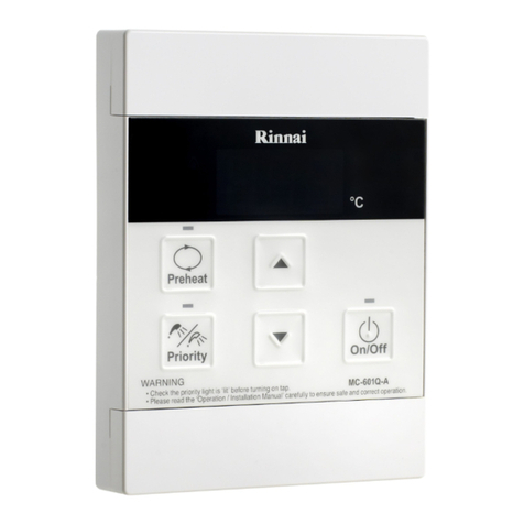
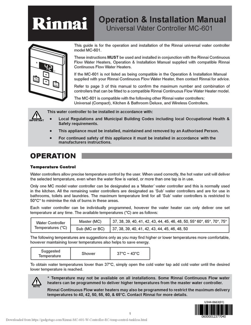
Rinnai MC-601 User manual

Rinnai

Rinnai MC-601 User manual

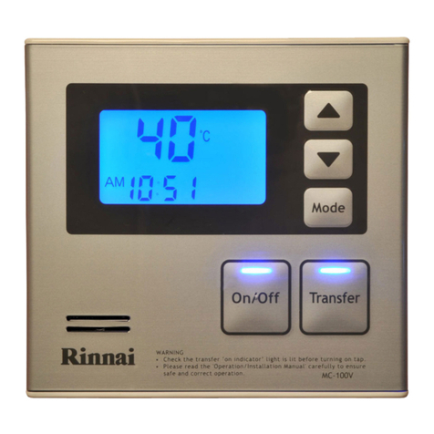
Rinnai MC-100V User manual

Rinnai

Rinnai MC-100V User manual

Rinnai Demand Duo User manual

Rinnai

Rinnai Demand Duo User manual

Rinnai Infinity V26 series Service manual

Rinnai

Rinnai Infinity V26 series Service manual

Rinnai BRIVIS Touch User manual

Rinnai

Rinnai BRIVIS Touch User manual

Rinnai MC502S User manual

Rinnai

Rinnai MC502S User manual

Rinnai CNTRLDRCIZHAW Quick guide

Rinnai

Rinnai CNTRLDRCIZHAW Quick guide

Rinnai MC-601Q User manual

Rinnai

Rinnai MC-601Q User manual

Rinnai RS100 Troubleshooting guide

Rinnai

Rinnai RS100 Troubleshooting guide

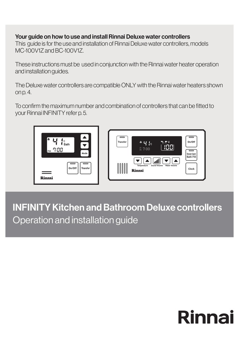
Rinnai BC-100V1Z Quick start guide

Rinnai

Rinnai BC-100V1Z Quick start guide

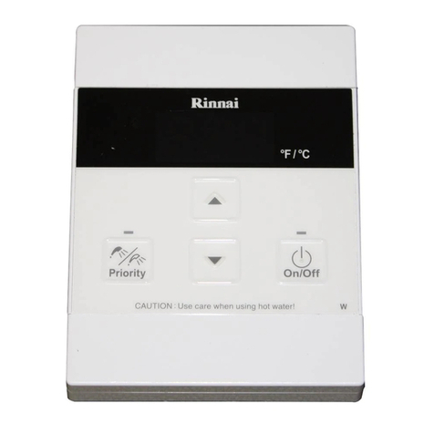
Rinnai MC-601-W User manual

Rinnai

Rinnai MC-601-W User manual

Rinnai Demand Duo Operating instructions

Rinnai

Rinnai Demand Duo Operating instructions

Rinnai MC-100V Specification sheet

Rinnai

Rinnai MC-100V Specification sheet

Popular Controllers manuals by other brands

ABB PSTX Series Installation and commissioning manual

ABB

ABB PSTX Series Installation and commissioning manual

Auto Ingress LOGICSLIDE LogicSwing Owner operating instructions

Auto Ingress

Auto Ingress LOGICSLIDE LogicSwing Owner operating instructions

ESBE CRD100 Series manual

ESBE

ESBE CRD100 Series manual

Cole Parmer CN-200 Series instruction manual

Cole Parmer

Cole Parmer CN-200 Series instruction manual

Kimo LEKTROMIK DS1 product manual

Kimo

Kimo LEKTROMIK DS1 product manual

Mannesmann INDRAMAT ECODRIVE DKC01.1 troubleshooting guide

Mannesmann

Mannesmann INDRAMAT ECODRIVE DKC01.1 troubleshooting guide

Daikin RoCon U1 manual

Daikin

Daikin RoCon U1 manual

Zapi COMBI SEM-1 user manual

Zapi

Zapi COMBI SEM-1 user manual

Resol DeltaSol C2 manual

Resol

Resol DeltaSol C2 manual

PMA STB55 operating manual

PMA

PMA STB55 operating manual

INCOE VGC instruction manual

INCOE

INCOE VGC instruction manual

Watergates NA005 Original operating manual

Watergates

Watergates NA005 Original operating manual

Mitsubishi Electric PAC-YT51CRB installation manual

Mitsubishi Electric

Mitsubishi Electric PAC-YT51CRB installation manual

Fluidwell F124-P Operation manual

Fluidwell

Fluidwell F124-P Operation manual

Parker 690+ series product manual

Parker

Parker 690+ series product manual

Erreka VIVO-M201 Installer manual

Erreka

Erreka VIVO-M201 Installer manual

Wilo ER 2 Installation and operating instructions

Wilo

Wilo ER 2 Installation and operating instructions

KMC Controls KMD-5831 Installation & operation guide

KMC Controls

KMC Controls KMD-5831 Installation & operation guide

manuals.online logo
manuals.online logoBrands
  • About & Mission
  • Contact us
  • Privacy Policy
  • Terms and Conditions

Copyright 2025 Manuals.Online. All Rights Reserved.