Rinnai Energysaver 309FT3 Quick start guide


Important
Appliance must be installed with a Rinnai approved ue system.
This appliance must be installed in accordance with:
- Manufacturer’s installation instructions
- Current AS/NZS 3000, AS/NZS 3500, AS/NZS 5601.1:2013 and G12/AS1
For use with Natural Gas or Universal LPG as indicated on the appliance.
Appliance must be installed, commissioned and serviced by an authorised
person, being in New Zealand a licensed gastter.
Please retain this manual for future reference.
Warning
Improper installation, adjustment, alteration, service and maintenance can
cause property damage, personal injury or loss of life.
For more information about buying, using, and servicing of Rinnai appliances
call: 0800 RINNAI (0800 746 624).
Rinnai New Zealand Limited
105 Pavilion Drive, Mangere, Auckland
PO Box 53177, Auckland Airport, Auckland 2150
Phone: (09) 257-3800
Email: [email protected]
Web: rinnai.co.nz
youtube.com/rinnainz
facebook.com/rinnainz

About your Energysaver ............................................. 4
Safety ......................................................................... 6
Important .................................................................... 7
Setting the clock ......................................................... 8
Setting and operating the timers................................. 9
Additional heater information ...................................... 10
Care and maintenance ............................................... 11
Troubleshooting .......................................................... 12
Error codes ................................................................. 13
Installation
Carton contents and item checklist............................. 15
Energysaver specication summary ........................... 16
Energysaver dimensions (mm) ................................... 17
Positioning, gas, and electrical supply........................ 18
Energysaver ueing guidelines................................... 19
Energysaver ueing options (most common) ............. 20
Installation .................................................................. 21
Commissioning ........................................................... 23
Wiring diagram RHFE-309, 559, 561FT3 ................... 24
Wiring diagram RHFE-1005FT3 ................................. 25
Installation checklist and Installer details.................... 26
Purchase details ......................................................... 27
Limited Warranty ........................................................ 28
Contents
Gas appliances, like cars, require regular maintenance and servicing. For reliable
operation Rinnai Energysavers, in residential applications, should be serviced every
two years, including inspection of the ue system.

4
About your Energysaver
Congratulations on the purchase of your Rinnai Energysaver. We hope you love this product as
much as we do, and on the o chance that something does go wrong, or if you need help, we’re
only a phone call away.
Features
Push button ignition Only one-touch is required to turn the heater on and o.
Lock function Prevents children from altering settings when the heater is in use or
activating the heater when turned o.
Preheat Automatically functions in conjunction with the timers. When a timer is
selected, the heater may operate anywhere within an hour prior to the
programmed on time. The preheat function ensures the room reaches
the desired temperature by the programmed start time.
Economy Energy saving feature designed to control the room temperature and
prevent the room from overheating.
Override Temporarily changes the heater operation from on to o, or o to on,
until the next programmed setting is reached.
Timer 1 / Timer 2 Allows you to program the appliance to come on for two separate
periods each day, one in the morning and one in the evening.
Filter indicator When the lter becomes covered with dust the lter indicator will ash
indicating that cleaning is necessary.
Humidier tray Raise humidity in the room for extra comfort with the humidier tray—
can be lled with water as required.
On/O button
Main switch for turning the heater on and o. To turn on, press the ON/OFF button, the heater will
glow green, the spark generator will be heard before the burner ignites and the indicator will glow
red. When the heater warms up the fan will start.
To turn the heater o, press the ON/OFF button, the indicator light will go out. The fan will continue
to operate for a short time to cool the appliance.
Set times
Selects clock, timers, or temperatures for adjustment or programming.
Temp and time
Increases or decreases the temperature as well as changing the hours or minutes when in
programming mode.

5
Override
Temporarily changes operation from ON to
OFF or OFF to ON until the next programmed
setting is reached.
Timer 1 and Timer 2
Displays which timer is operating.
Lock
Locks all controls when pressed except OFF.
Hold for two seconds to deactivate. If the lock is
pressed while the heater is o all functions will
be locked, including turning the heater on, until
it is deactivated.
Filter
Indicates the lter needs cleaning. If you do
not clean the lter at regular intervals and the
lter indicator is allowed to remain ashing, the
appliance will stop and the display will show
error code 14. The lter will need cleaning
before the appliance can be turned back on.
Clock and timer indicators
When programming, the indicators will glow to
indicate what is being programmed. The ‘Temp’
indicator indicates the set temperature for the
timer that is being set.
Display window
Shows either the time of day, temperature or
error code.
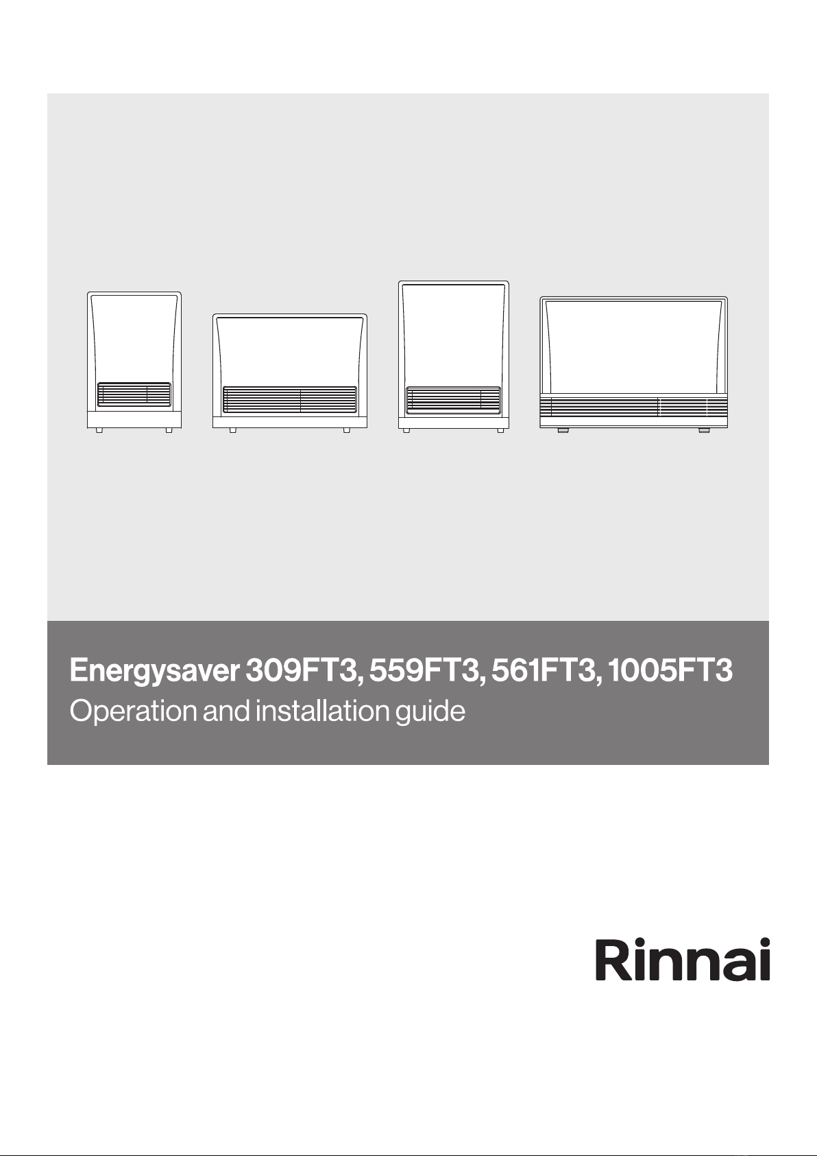
Adjusting the room temperature
Pressing the up and down arrows will
change the preset temperature by 1 °C. The
temperature will be shown in the display
window. The room temperature sensor is
located behind the Energysaver so the
temperature on the display may vary slightly
from the actual room temperature.
The temperature can be set to:
L (low)
Typically used to keep the chill o a large room.
The unit operates on the lowest burner setting. If
the room temperature is above 10 °C, the burner
will switch o, the fan will wind down, and the
appliance will stop heating. If the temperature
then drops below 10 °C the heater will switch
back on.
16-26 °C
Unit will modulate, and in some instances
turn o and on, to maintain the selected
temperature.
H (high)
Unit operates on the highest burner setting.
The ‘L’ and ‘H’ settings are not normally
used as this means the heater operates
without a set temperature.
Economy
Prevents the room overheating and reduces
gas consumption.
How it works
After the room reaches the set temperature,
the set temperature will automatically start
decreasing, dropping by a maximum of 1 °C
in 30 minute blocks, until ‘comfort control’ is
reached. When in comfort control the unit alters
combustion and fan speed to keep the room at
a comfortable temperature.
2 1 2 1
AM
PM
Set Room
Temp
Time
NOTE
Set
room
temp. Max. 1 °C
Max. 1 °C
Total 2 °C Comfort control
Economy indicator illuminates

6
Safety
• Not to be connected to an LPG gas cylinder located indoors
• Do not place articles on or against this appliance
• Do not use or store ammable materials near this appliance
• Do not modify this appliance
• Do not spray aerosols in the vicinity of this appliance while operating
This appliance is not intended for use by persons (including children) with reduced physical,
sensory or mental capabilities, or lack of experience and knowledge, unless they have been given
supervision or instructions concerning the use of this appliance by a person responsible for their
safety.
The power point must be to the side of the heater. It must not be above the unit as this is a
potential re hazard.
Do not restrict the warm air discharge by
placing articles in front of the heater. This
appliance must not be used for any purpose
other than heating.
Do not allow anyone to post articles
through the louvres, or let ammable and
combustible materials come into contact
with the heater. Do not place articles on or
against the heater.
Do not spray aerosols while the appliance
is operating. Most contain butane gas
which can be a re hazard if used near the
appliance. Do not use or store ammable
materials near this appliance. Combustible
materials must not
be placed where the
heater could ignite
them.
A dedicated 230 V 10 A power point must
be used with this heater. Do not use double
adaptors to operate this appliance.
Do not unplug the heater while it is still in use
or while the fan is on.
Children should be supervised at all times
to ensure they do not play with the heater.
Hand or body contact with the heater must
be avoided, especially with the louvres,
which can become very hot. Do not allow
anyone to sit, lean or
sleep directly in front of
the heater.
When the heater is used for the rst time
or after long periods of not being used, a
slight odour may be emitted—this is normal.
If odours persist turn the appliance o and
contact Rinnai.

7
Important
Clearances while the heater is operating
This appliance must not be installed where
curtains or other combustible materials could
come into contact with it. In some cases
curtains
may need
restraining.
250mm
50 mm 50 mm
1000 mm
Floor protection
Energysavers discharge a large volume
of warm air at a low level. Heat over
time may aect the appearance of some
ooring materials, such as, carpet, vinyl,
cork, or timber. To avoid this occurring, it is
recommended that
a mat be placed
in front of the
appliance.
Outside ue terminal
Keep ammable materials, trees, shrubs, etc.
away from the ue terminal. In areas subject
to heavy snowfall, keep snow clear of the
ue terminal at all times.
Snow
Outside ue terminal
On cold days steam may be discharged
from the ue terminal. This is normal with
high eciency gas appliances like the
Energysavers and does not indicate a fault.
Filters
During peak operating periods the lter(s)
should be cleaned weekly. If the ‘Filter’
warning indicator ashes on the control panel
display, immediately turn o the appliance
and when the heater has cooled, clean the
lter(s) before starting
again.
On/Off
On
Filter
Humidier tray
Do not overll—there is a maximum water
level indicator in the tray. Also do not ll while
the heater is operating, more information on
p.10.
Humidifier tray
Access
panel
Access
panel
Max.
fill line
Humidifier tray
Filler spout
Max.
fill line
Energysavers must not be built into bookcases or walls etc.
Energysavers are not recommended for installations in unusually dusty environments such as hair
salons or where there are a large number of pets—this will cause continual blockage of the lter(s).
At least
750mm

8
Setting the clock
On O Temp
On/O
On
When the appliance is rst plugged in or after a power failure the digital display will show --: --.
▲= UP button ▼= DOWN button
Setting the clock (example - setting the clock to 6:00 am)
1. Press the Set Times button once, the clock indicator will ash.
2. Press and hold the UP button. It will cycle quickly through the minutes and then hours. Once
you reach 6:00 AM release the UP button. If you need to add minutes keep pressing UP until
the desired time is reached.
3. Conrm that you have selected AM, a small indicator on the left hand side of the digital display
indicates the AM setting.
4. Press the Set Times button seven times to lock in the set time. The Clock and Timer indicators
will go out and a small indicator on the display will ash to show the clock is operating. The
display will dim approximately 10 seconds after the last button is pressed.
Digital display
The digital display is turned o when the appliance is turned OFF.
Daylight saving
Follow steps 1-4 to adjust for daylight saving and anytime the clock needs to be adjusted.

9
Setting and operating the timers
Before operating the timers the clock must be set.
The timers can be programmed to operate for any two time periods in 24 hours. A timer start and
nish time, and a set temperature must be set for the timers to work. The programmed time and
temperature must be selected and locked-in within one minute of the indicators ashing for the
information to be saved.
Setting the timers and temperature
Example, program Timer 1 to heat the room by 7:10am and nish at 9:00am, at a temperature of
20°C.
1. Press the Set Times button twice. The digital display will show AM 6:00 and the Timer 1
indicator will ash. Press the UP or DOWN button until 7:00 appears, release, then press the
UP or DOWN button again until AM 7:10 appears.
2. Press the Set Times button again, the Timer 1 OFF indicator will ash. Press the UP or DOWN
button until AM 9:00 appears—the default is 9:00am.
3. To set the temperature use the UP or DOWN button until 20 appears.
4. Press the Set Times button four times to lock in the settings. The digital display will show the
current time.
Timer 2 is programmed the same way—remember to ensure that the Timer 2 indicator is flashing
before you start programming. The Timer 2 default settings are PM 5:00 on and PM 9:00 off. When
finished press the Set Times button until you get back to the main display.
Operating the timers
1. Press the ON/OFF button (ensure the clock and timer indicators are not ashing), the ON
indicator will glow green.
2. Press the Timer 1 and Timer 2 buttons. The timer indicators will glow and the heater will remain
on standby until the timer setting is reached—the timer indicator will ash and the heater will
turn on.

10
Additional heater information
Humidier tray
Your heater is tted with an enamel humidier
tray. To ll the tray, open the access panel as
shown below. Pour water into the tray, or in the
case of the 1005, pour water into the ller spout
built into the access panel.
309 / 559/ 561
1005
If you notice water in the humidier tray, but
you have not placed any in there do not be
alarmed, this is normal. This will be condensate
from the ue system—designed to drain into
the humidier tray.
If you are using the humidier tray, it will need
lling approximately once a day.
• Do not ll the humidier tray while the
heater is on, it will be very hot and could
cause burns—turn the heater off and wait at
least ve minutes.
• Do not operate the heater without the
humidier tray in place.
Vertical louvre adjustment
When the heater is turned o the direction of
the warm air ow may be altered by carefully
inserting a screwdriver or similar tool and gently
bending the vertical louvres to the left or right.
The louvres are not designed to be adjusted
more than six times as they will weaken and
break.
Power failure
If a power failure occurs the unit will turn itself
o. After power has been restored the unit will
automatically turn on again—you may need to
reset the clock depending on the length of the
power cut.
If timer settings have been programmed the
system memory will retain the timer settings,
but the clock will stop at the time the power
goes o and will be slow by however long the
power has been o.
Preheat
Automatically functions in conjunction with the
timers. When a timer is selected, the heater
may operate anywhere within an hour prior
to the programmed on time. The preheat
function ensures the room reaches the desired
temperature by the programmed start time.
Pull
Push
Access
panel
Max.
fill line
Access panel
Max. fill line
Humidifier tray
Filler spout
Pull

11
Care and maintenance
Before cleaning any part of the heater ensure
it is turned o and has cooled down. All parts
of the heater can be cleaned using a soft damp
cloth and mild detergent—do not use solvents.
If the humidier tray gets dirty it can be washed
in warm soapy water.
Fan lter(s)
To protect the appliance
from dust or lint a lter
(two in the case of the
1005) is located at the
rear of the appliance.
If the lter becomes
blocked the lter
indicator will ash to
indicate that it should be
cleaned.
The build up of dust on the lter reduces
the air ow through the heater. This reduces
the eciency and can lead to the appliance
shutting down. Regular (weekly) lter cleaning
during the heating season will stop this from
happening.
If you do not clean the lter at regular intervals
and the ‘Filter’ indicator is allowed to remain
ashing, the appliance will stop (ON indicator
will ash and the display will show error code
14). The lter will need to be cleaned before
operating the appliance again.
• Do not remove the lter when the appliance
is operating.
• Do not use the heater with the ‘Filter’
indicator ashing as this may cause the
appliance to overheat.
Cleaning the fan lter(s)
• Dry dust/lint: Use a duster or vacuum to
remove the dust.
• Oily residue: Wash using a mild detergent,
drain o the water, and dry.
Ensure the fan lter is tted back into
the appliance after cleaning. DO NOT
operate the appliance without the lter
in place.
Maintenance and servicing
Rinnai has a maintenance, service and spare
parts network with personnel who are fully
trained and equipped to give the best advice on
your Rinnai appliance. If your appliance needs
maintenance or servicing, please call Rinnai
(0800 746 624).
For reliable operation your Rinnai Energysaver,
including inspection of the ue section, should
be checked by a licensed tradesperson every
two years. If located in a particularly dusty area
or subject to excess lint, for example dog hair
or where there are newly laid carpets, then
annual servicing would be benecial.
Regular maintenance and servicing is not
covered by the Rinnai warranty.
If you have any other faults or problems, please
contact your installer or call Rinnai.
WARNING

12
Troubleshooting
Check the following information before making a service call. If you are still unsure or concerned
after reading this section, please contact Rinnai.
Using the heater for the rst time, or after a long period of non use
The heater may not start the rst time it is operated due to air in the gas pipes. If ignition does not
occur within approximately one minute the heater will attempt to start again. If it does not start the
unit will switch itself o automatically—this is a safety feature. Try switching the heater back on if
this occurs.
What’s happening Explanation and/or possible solution
Warm air not coming from the heater when it
starts.
The heater’s fan will start automatically after
a short delay. This is to allow the appliance to
warm up and to stop cold draughts.
Smoke or strange smells coming from the
heater after it has been installed.
This is caused by grease, oil, or dust within the
appliance. It will stop after a short time.
Clicking noises when the heater starts or
stops, or changes to a higher or lower setting.
This is the expansion and contraction of
the heat exchanger and is a normal part of
operation.
Clunking noise when the thermostat operates. This is the sound of the gas valve opening
and closing to regulate the ow of gas and is a
normal part of operation.
Fan continues to run after the heater is turned
o.
This is to remove the heat from the appliance
and will stop once the heater has cooled down.
Timer(s) do not operate at the set time. Check the timers are set correctly as they may
be inactivated or incorrectly programmed.
Smell of gas. There may be a small leak in the appliance.
Turn the heater o and contact Rinnai.
Heater doesn’t start. Check power cord is plugged in properly.
Check the lock isn’t on.

13
Error codes
The Energysaver range has built-in technology to continually monitor performance. If a fault occurs
an error message will ash on the digital display on the control panel. This assists with diagnosing
the fault and may enable you to overcome a problem without a service call.
In all cases you may be able to clear the error by turning the heater o and on again. If the error
code remains or returns when the heater is used again, contact Rinnai.
Faults caused by insucient gas supply, gas quality, installation or operation errors are not covered
by the Rinnai warranty.
Error code Likely cause Suggested solution
11 Ignition failure Check gas supply is turned on, turn the
heater OFF then ON again. If the error
persists a service call is required.
12 Flame failure As above.
14 Filter blockage/overheat Clean lter(s), if the error continues a
service call is required.
16 Room overheat* Lower the room temperature below 40 °C.
30 Overheat temperature sensor faulty Service call.
31-32 Room temperature sensor faulty Service call.
33-35 Overheat temperature sensor faulty Service call.
40 Sensor sensing tube failure Service call.
Installer: Conrm commissioning has
been completed in accordance with the
instructions. Ensure that the pressure
check tube is not blocked, pinched or
crushed.
49 Sensor breakdown Service call.
53 Spark sensor faulty Service call.
61 Combustion fan faulty Service call.
62 Convection fan faulty Service call.
70 Faulty ON/OFF switch Service call.
71 Faulty solenoids Service call.
72 Flame detection circuit fault Service call.
73 Communication error Service call.
81 Faulty solenoids Service call.
99 Flue terminal blocked Owner: Check that the ue terminal is free
of any obstructions. If the error persists a
service call is required.
Installer: Conrm commissioning has
been completed in accordance with the
instructions. Check that the ue terminal
is free of any obstructions. Ensure that
the pressure check tube is not blocked,
pinched or crushed.
* If the unit detects 40 °C for over ten minutes, the unit will stop operating.

14
Installation
Installation, servicing and repair shall be
carried out only by authorised personnel.

15
Carton contents and item checklist
Unpacking the appliance
The heater is supplied in one carton. This contains the heater, standard rear panel set, screw pack,
and additional installation components—refer table below for details.
Remove all packaging materials and check for damage. If any damage is evident do not install or
operate the appliance—contact your place of purchase for advice.
Before installing the heater, check it is labelled for the correct gas type. Refer to the data label at
the rear of the heater.
The heater does not come supplied with ue components. These are purchased separately. Only
Rinnai Energysaver ue components can be used with this appliance.
Carton contents and item checklist, check you have:
• One of the following Rinnai Energysavers
- RHFE-309FT3 - RHFE-559FT3
- RHFE-561FT3 - RHFE1005FT3
• One rear panel set comprising of left, right, and top panels
• One pack containing the following
PART RHFE-1005FT3 RHFE-309/559/561FT3
Plastic inlet hose clips (holds the air intake hose in place) 02
Air intake bae ring* (ensures the max. eciency on the heater) 0 1
Stainless steel sheath clamp (holds the protective sock on the
exhaust pipe in place)
1 1
Securing brackets (secures the heater to the wall) 2 2
Cable tie (secures the air inlet elbow onto the ue) 1 1
Flue lock clamp (secures the exhaust pipe assembly
onto the ue)
1 - large
1- small
1 - small
Screw pack 1 1
* The air intake bae ring is only required to be installed on the 309, 559, and 561 models which use the ESDFK
component in a direct ue installation. It improves the eciency of the unit slightly. It is not critical to the safe operation of
the unit and does not need to be tted if it has been misplaced.
Plastic inlet hose clip Stainless steel sheath Cable tie Flue lock clamp

16
Energysaver specication summary
309FT3 559FT3 561FT3 1005FT3
Colour White with grey
louvres and rear
panel
White with grey
louvres and rear
panel
White with grey
louvres and rear
panel
White with grey
louvres and rear
panel
Input* 5.8-13 MJ/h 9-23 MJ/h 9-23 MJ/h 15.5-37 MJ/h
Output* 1.3-3.2 kW 2.2-5.3 kW 2.2-5.3 kW 3.5-8.9 kW
Temp. range 16-26 °C 16-26 °C 16-26 °C 16-26 °C
Eciency* 84.6% 82.8% 82.9% 83.4%
Noise level 31-38 dB(A) 33-42 dB(A) 34-42 dB(A) 39-45 dB(A)
Power
consumption
Approx. 24 W (high)
<1 W on standby
Approx. 30 W (high)
<1 W on standby
Approx. 36 W (high)
<1 W on standby
Approx. 59 W (high)
<1 W on standby
Gas connection 15 mm BSP male
thread
15 mm BSP male
thread
15 mm BSP male
thread
15 mm BSP male
thread
Humidier tray
capacity
0.8 L 1.0 L 1.0 L 3.0 L
Data plate position Lower RHS Lower RHS Lower RHS Lower RHS
Injectors NG 2 x Ø1.25 mm 4 x Ø1.25 mm 4 x Ø1.25 mm 4 x Ø1.50 mm
1 x Ø0.45 mm
Injectors ULPG 2 x Ø0.85 mm 4 x Ø0.82 mm 4 x Ø0.82 mm 4 x Ø1.00 mm
1 x Ø0.30 mm
Remote switching
capability
Yes** Yes** Yes** Yes**
Weight 19 kg 24 kg 23 kg 40 kg
Features • Preheat function
• Dual timers
• Manual control
• Electronic ignition
• Economy mode
• Fan lter
• Overheat safety device
• Lock
* Input, output, and eciency will vary depending on gas type and ue length
** Requires the remote switching kit R1349
For gas pressures and gas type, refer to the data plate on the lower right hand side of the appliance

17
Energysaver dimensions (mm)
465
695
257 85
309FT3
760
582
257 85
559FT3
545
750
262 85
561FT3
115
330
930
670
1005FT3
Gas inlet
335
124
Gas inlet
134
82
Gas inlet
350
114.5
Gas
inlet
550
92

18
Positioning, gas, and electrical supply
Positioning
The main points governing the location of the heater are ueing and warm air distribution. The
heater must not be installed where curtains or other combustible materials could come into contact
with the appliance, refer clearances diagram below. In some cases curtains may need restraining.
Energysavers are not recommended for installations in unusually dusty environments such as
hair salons or where there are a large number of pets, these environments will cause continual
blockages of the fan lter.
Energysavers MUST NOT be built into bookcases or walls.
Gas supply
The gas supply terminates outside the heater at the rear of the appliance. The gap required
between the wall and the heater body is 85 mm for the standard rear panels (115 mm for the
1005FT3), or 200 mm for the back spacer kit (230 mm for the 1005FT3).
Gas piping must consider the gas input to this appliance as well as other gas appliances in the
building. An approved sizing chart such as the one in AS/NZS 5601.1:2013 should be used.
All foreign materials, such as lings, must be purged from the gas supply as they may cause the
gas control valve to malfunction.
Electrical supply
The electrical connection is to the right hand side of the heater (passes out
behind the heater). A 3-pin plug with a 1500 mm power cord is supplied. This
must be connected to a dedicated earthed power point. The power point must
not be above the unit as this is a potential re hazard.
Alternatively the appliance can be direct wired if the power supply is to
be concealed. The electric isolation switch MUST BE accessible after the
appliance has been installed. Consult a qualied electrician if direct wiring is required as this must
comply with the requirement of AS/NZS 5601.1:2013 and AS/NZS 3000 and other relevant local
regulations.
If the supply cord is damaged and requires replacing, it must be replaced by a licensed
tradesperson. This must be a genuine replacement part available from Rinnai.
250mm
50 mm 50 mm
1000 mm

19
Energysaver ueing guidelines
Every Energysaver heater requires a ue system that will draw eectively and clear products safely
under all potential wind and climatic conditions. It is the responsibility of the installer to ensure
that the appliance is provided with an eective ue. Some guidelines to assist with ue design
are in this guide. These must be read and modied as necessary with reference to the particular
installation.
All Rinnai Energysavers must be installed with an approved Rinnai ue system.
Flue clearance to combustibles
Energysaver ue components, except
the elbow section of the ESKIT03, and
ESELBOWB, have zero clearance.
The ESKIT03 and ESELBOWB require a
minimum clearance of 25 mm from combustible
materials.
Condensate trap
A condensate trap is required for all vertical
installations to ensure condensate generated
during combustion is trapped and prevented
from entering the chamber of the heater.
2° fall to wall terminal
For direct, sideways, and down-and-out
installations there must be a continuous fall
of 2° to the wall terminal (equates to 20 mm
per metre). The Energysaver A/AA direct
mushroom ues have an inbuilt 2° fall, and the
wall plate of the ESDFK kit has a 2° offset.
Flue terminal locations
Must be compliant with AS/NZS 5601.1:2013.
• Do not ue into natural draft ues or
replaces
• Do not ue into other rooms, roof spaces,
or under oor spaces
The flue terminal must be positioned away from
flammable materials.
Keep snow and other items, such as outdoor
furniture well clear of the flue terminal at all
times.
Flashings
Flashings are not part of the ue kit and must
be specied.
Vertical ue cowl clearance
To ensure products of combustion are cleared,
adequate clearance from the building is
required.
The flue cowl should have a 500 mm clearance
from any part of the building. This also applies
to steeped and pitched roofs where the flue
cowl should be 500 mm clear of the ridge line.
An adequate flow of fresh air must exist around
the flue cowl following installation. Minimum
clearances are shown in AS/NZS 5601.1:2013.
Maximum ue length and number of bends
Maximum ue length = 9 m
Maximum number of bends = 3
One 90° bend equals 1 m. For every 90° bend
the overall length must be reduced by 1 m. For
example, if an installation has three 90° bends,
the maximum flue length can be 6 m.
The ue transition connection for the ESKIT03
and ESELBOWB is counted as a 90° bend.
Elbow section
Minimum clearance
500 mm to nearest
part of roof

20
Energysaver ueing options (most common)
Direct and direct extended ueing
Direct through the wall ueing for walls
75-385 mm thick.
Flue can be extended if wall thickness is
greater than 385 mm using the ESDFK
and additional lengths of ue pipe
ESPIPE900.
Direct
R1350: Mushroom ue kit for walls 75-115 mm
R1351: Mushroom ue kit for walls 115-240 mm
ESDFK1: Straight horiz. kit for walls up to 385 mm
Direct extended
ESDFK1 + ESPIPE9002
Sideways extension ueing
Flue runs along the left or right hand
side of an internal wall behind the unit.
If retrotting the ue can be boxed in
along the oor or behind a 125 mm false
wall. The installation requires additional
clearance o the wall, a back spacer kit
is required.
Sideways in-wall
ESDFK1 + ESELBOWB + ESPIPE9002
Sideways front-of-wall
Back spacer kit + ESDFK1 + ESPIPE9002
Vertical extension through-wall ueing
Flue runs directly from the unit to a
vertical termination on the roof.
Examples for this option would be
an Energysaver installed against a
solid brick wall or where there are ue
clearance restrictions.
ESDFK + ESBEND3 + ESPIPE9002 + ESCONDK +
ESROOFCOWL
Vertical extension in-wall ueing
Flue is installed within a stud wall,
minimum cavity depth 90 mm, and is
run vertically. This type of installation is
usually completed at the framing stage.
A - Direct
ESKIT03 + ESPIPE9002 + ESROOFCOWL
B - Oset
ESKIT03 + ESPIPE9002 + ESBEND3 x 2 +
ESROOFCOWL
Down and out ueing
Flue runs below the oor to an external
termination—must have a continuous
fall of 2° to the termination point to drain
condensate. Ideal for Energysavers that
need to be located in a central position
of a building.
If not going in-wall the ue will require
additional clearance o the wall—back
spacer kit required.
Down and out
Back spacer kit + ESDFK1 + ESPIPE9002+
ESBEND3
Down and out in-wall
ESELBOWB + ESDFK1 + ESBEND3 + ESPIPE9002
Down and out through-wall4
ESDFK1 + ESBEND3 x 2 + ESPIPE9002
1 Use terminal o ESDFK on outside wall 2 ESPIPE900, order lengths as required
3 ESBEND kit contains 2 x 45° bends 4Installation that goes out into another room then down and out
This manual suits for next models
3
Table of contents
Other Rinnai Heating System manuals
Popular Heating System manuals by other brands

THERMAL INTEGRATION
THERMAL INTEGRATION DATA installation instructions

International Thermal Research
International Thermal Research CO32D Operator's manual

Ducasa
Ducasa AVANT-DGi+ 350 Operating and installation instructions

Viessmann
Viessmann VITOCELL 300-H Technical guide

Baxi
Baxi LUNA SAT Installation and operating manual

Salda
Salda RIS 700PE EKO 3.0 Technical manual