manuals.online logo
Brands
  1. Home
  2. •
  3. Brands
  4. •
  5. Rinnai
  6. •
  7. Water Heater
  8. •
  9. Rinnai REU-VRM2632WC User manual

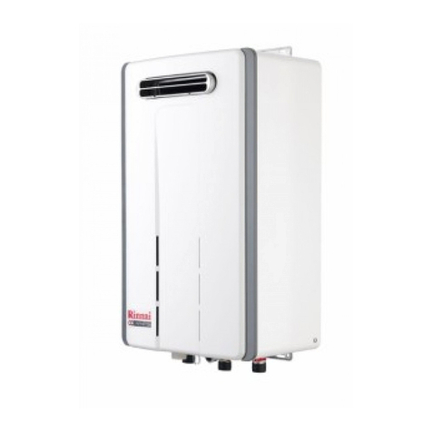
Rinnai REU-VRM2632WC User manual

Before final connection of the water heater purge gas, hot water and
cold water supply lines. Swarf in either the gas or water supplies may
cause damage.
Turn on gas and cold water supplies.
Test for water leaks and gas escapes near the unit.
Isolate gas supply. Remove test point screw located on the gas inlet
connection and attach pressure gauge.
Turn the power 'on' at the power point socket and turn on gas.
Open all available hot water taps. (CAUTION: Ensure building
occupants do not have access to hot water outlets during this
procedure.)
Operate ALL other gas appliances at their maximum gas rate, in
accordance with manufacturers instructions.
With all gas appliances in operation at maximum gas rate, check the
inlet gas pressure. If the pressure is lower, the gas supply is inadequate
and the appliance will not operate to specification. It is the Installers
responsibility to check the gas meter, service regulator and pipe work
for correct operation/sizing and rectify as required. Note that the gas
regulator on the appliance is electronically controlled and factory pre-
set. Under normal circumstances it DOES NOT need adjustment during
installation.
Close hot water taps including the shower.
Inspect and clean the strainer located on the cold water inlet
connection. This procedure may need to be repeated to ensure the
strainer remains clear, especially on new installations.
If Temperature Controllers are fitted, it is necessary to test their
operation through the complete range of functions. (Refer to the 'How to
use your Water Heater' booklet.)
Confirm the hot water delivery temperature(s) using a thermometer. If
controllers are fitted, ensure temperatures exceeding 50˚ C cannot be
selected on bathroom or ensuite controllers.
After testing is completed, explain to the householder the functions and
operation of the water heater and temperature controllers (if fitted).
TESTING AND COMMISSIONING
1.
2.
3.
4.
5.
6.
7.
8.
9.
10.
11.
12.
13.
AC weatherproof external earthed power point is required within 1500 mm
of the appliance.
The appliance weighs approx. A, depending on the wall on which it is to be
mounted must be capable of supporting it and associated pipework. Ensure
that suitable fixing screws or bolts are used to secure the appliance to the
wall. Bracket and fixing hole locations are shown overleaf.
The top bracket has a keyhole slot so that the appliance can be positioned
by hanging it on one screw, then the other screws can be secured. After
determining the most suitable position, fix the appliance to the wall.
Connect hot and cold water and gas pipes. Approved valves MUST BE
FITTED to both the cold / hot water pipes and the gas inlet.
In areas where the water pressure is over 1000 kPa, a pressure limiting
valve must also be fitted. the gas connection is B, the cold water inlet and
hot water outlet connections are C. Locations are shown overleaf.
The appliance range can use up to Dof gas.
IF THE GAS PIPE SIZE IS INSUFFICIENT, THE CUSTOMER WILL NOT
GET THE FULL PERFORMANCE BENEFIT. An approved isolation valve
MUST BE FITTED to the gas inlet. Connection size is B. This is NOT an
indication of the size of pipe required. Check the data plate for gas inlet.
This appliance is not suitable for use as a pool heater.
Never connect an earth wire to gas supply line.
This appliance is for OUTDOOR use.
INSTALLATION-GENERAL
REU-VRM2632WC / VRM3237WC
POSITIONING
This external model is an externally mounted, power flued appliance.
IT MUST ONLY BE FITTED OUTSIDE THE BUILDING.
When determining a suitable position for the appliance, the length of hot
water pipe runs should be taken into consideration. In principle, the
appliance should be as close as possible to the most often used taps, or in
a central location between taps, showers etc.
See diagram overleaf for position of gas, water and power connections.
The location of the flue terminal must comply with the clearances shown in
the following diagram.
Min. clearances
(mm)
Ref. Item
Fan assisted
Below eaves, balconies and other projections:a
·Appliances over 50 MJ/h input 300
b From the ground, above a balcony or other surface †300
c From a return wall or external corner †300
d From a gas meter (M) 1000
e From an electricity meter or fuse box (P) 500
f From a drain pipe or soil pipe 75
g Horizontally from any building structure †or obstruction facing a
terminal 500
h From any other flue terminal, cowl, or combustion air intake †300
Horizontally from an openable window, door, non-mechanical air inlet, or any other opening
into a building with the exception of sub-floor ventilation:
·Appliances up to 200 MJ/h input 300
·Appliances over 200 MJ/h input up to 250 MJ/h input † 500
·Appliances over 250 MJ/h input † 1500
j
·All fan-assisted flue appliances, in the direction of discharge 1500
k From a mechanical air inlet, including a spa blower 1000
Vertically below an openable window, non-mechanical air inlet, or any other opening into a
building with the exception of sub-floor ventilation:
·Space heaters up to 50 MJ/h input 150
·Other appliances up to 50 MJ/h input 500
·Appliances over 50 MJ/h input and up to 150 MJ/h input 1000
n
·Appliances over 150 MJ/h input 1500
g
openable
window
door
M
P
g
T
b
d
d
e
e
See note 2
h
h
a
h
j
j
j
n
k
k
c
c
f
T = Flue terminal
I = Mechanical air inlet areas for flue terminals
T
T
I
Shading indicates prohibited
M = Gas meter
P = Electricity meter or fuse box
A(the appliance weights) 19kg
VRM2632WC
R3/4(20mm)
R3/4(20mm)
199MJ/h
29kg
VRM3237WC
R3/4(20mm)
R3/4(20mm)
250MJ/h
B(gas inlet)
C(cold / hot water pipes)
D(input)
1
† Unless appliance is certified for closer installation
note 1. All distance are measured to the nearest part of the terminal.
note 2. Prohibited Area below electricity meter or fuse box extends to
ground level.
DIMENSIONS (VRM2632WC)
DIMENSIONS (VRM3237WC)
2
Dip.SW1
3
14.
15.
16.
17.
18.
19.
20.
21.
1.
2.
3.
4.
Note: 'ON' towards front, 'OFF' towards rear.
5.
6.
7.
8.
9.
10.
11.
12.
13.
Turn 'OFF' the gas supply.
Turn 'OFF' power supply.
Remove the front cover from the
appliance.
Check gas type switches (fig. 1) are in
the correct position (No.1 switch of
Dip.SW2 'ON' = NG, 'OFF' = LPG).
Attach pressure gauge to burner test
point, located on the gas control.
(fig. 2)
Turn 'ON' the gas supply.
Turn 'ON' power supply.
If remote controllers are fitted, turn the
unit 'ON' at the kitchen controller,
select the maximum delivery
temperature and open a hot water
tap fully. (CAUTION: Ensure
building occupants do not have access
to hot water outlets during this
procedure.)
Set the appliance to 'Forced Low'
combustion by setting No. 7 switch of
the Dip.SW1 set of dip switches to 'ON'.
(fig. 3)
Check the burner test point pressure.
Remove rubber access plug and
adjust the regulator screw on the
modulating valve (fig. 4) as required to
the pressure. (Table 1) Replace rubber
access plug.
Set the appliance to 'Forced High'
combustion by setting both No. 7 and
No. 8 switches of the bottom Dip.SW1
set to 'ON'. (fig. 5) Ensure maximum
water flow.
Check the burner test point pressure.
Adjust the high pressure Potentiometer
(POT) on the Printed Circuit Board
(PCB) as required to the pressure
shown Table 2.
IMPORTANT: Set No. 7 and 8 switches on the bottom (Dip.SW1) set
of switches to 'OFF' to return the appliance to 'Normal' combustion.
(fig. 6)
Close hot water tap.
Turn OFF the gas supply and power supply.
Remove pressure gauge, and replace sealing screw.
Turn 'ON' the gas supply and power supply.
Operate unit and check for gas leaks at test point.
Replace the front cover of the appliance.
REU-VRM2632WC / VRM3237WC
GAS PRESSURE SETTING
DURING PRESSURE TESTING OF THE CONSUMER PIPING
ENSURE GAS COCK SITUATED BEFORE UNIT IS SHUT-OFF.
FAILURE TO DO SO MAY RESULT IN SERIOUS
DAMAGE TO THE APPLIANCE AND POSSIBLE INJURY.
WARNING
The regulator on the Infinity is electronically controlled and factory pre-set.
Under normal circumstances it does not require adjustment during
installation. Perform this procedure only if the unit is not operating correctly
and all other possible causes for incorrect operation have been eliminated.
fig.1
fig.2
fig.3
fig.4
fig.5
fig.6
VRM2632WC
Ta ble. 1 Pressure Setting LOW
0.14
0.18
VRM3237WC
Ta ble. 2 Pressure Setting HIGH
NG
0.23
0.23
LPG
VRM2632WC 0.73
0.80
VRM3237WC
NG
1.20
0.98
LPG
(kPa)
(kPa)
WIRING DIAGRAM
Dip.SW1(8P)
Dip.SW2(6P)
Dip.SW2
Dip.SW1
Dip.SW1
080 00012 31518 7
REU-VRM2632WC-ASN
REU-VRM3237WC-ASN
U298-902(00)
DIAGNOSTIC POINTS
Burner test point
VRM2632WC VRM3237WC

This manual suits for next models

1

Other Rinnai Water Heater manuals

Rinnai RS11TML User manual

Rinnai

Rinnai RS11TML User manual

Rinnai RC80HPI User manual

Rinnai

Rinnai RC80HPI User manual

Rinnai Infinity XR26ia User manual

Rinnai

Rinnai Infinity XR26ia User manual

Rinnai R75LSI User manual

Rinnai

Rinnai R75LSI User manual

Rinnai HD70e User manual

Rinnai

Rinnai HD70e User manual

Rinnai Circ-Logic RL75i User manual

Rinnai

Rinnai Circ-Logic RL75i User manual

Rinnai Smart Cylinders ME13548830S Instructions for use

Rinnai

Rinnai Smart Cylinders ME13548830S Instructions for use

Rinnai RUC80i, RUC98i RU80e, RU98e User manual

Rinnai

Rinnai RUC80i, RUC98i RU80e, RU98e User manual

Rinnai V53De User manual

Rinnai

Rinnai V53De User manual

Rinnai REU-58E User manual

Rinnai

Rinnai REU-58E User manual

Rinnai REI-E380NP-B-WH Guide

Rinnai

Rinnai REI-E380NP-B-WH Guide

Rinnai REU-VR3237WG User manual

Rinnai

Rinnai REU-VR3237WG User manual

Rinnai REU-2007W User manual

Rinnai

Rinnai REU-2007W User manual

Rinnai RUC80i, RUC98i RU80e, RU98e Troubleshooting guide

Rinnai

Rinnai RUC80i, RUC98i RU80e, RU98e Troubleshooting guide

Rinnai REU-24 W-A User manual

Rinnai

Rinnai REU-24 W-A User manual

Rinnai Infinity EF24 User manual

Rinnai

Rinnai Infinity EF24 User manual

Rinnai Demand Duo 80 User manual

Rinnai

Rinnai Demand Duo 80 User manual

Rinnai RH180 User manual

Rinnai

Rinnai RH180 User manual

Rinnai RH180 Instruction Manual

Rinnai

Rinnai RH180 Instruction Manual

Rinnai INFINITY A-Series User manual

Rinnai

Rinnai INFINITY A-Series User manual

Rinnai R63LSe Specification sheet

Rinnai

Rinnai R63LSe Specification sheet

Rinnai Infinity 24e User manual

Rinnai

Rinnai Infinity 24e User manual

Rinnai RH180 Specification sheet

Rinnai

Rinnai RH180 Specification sheet

Rinnai Circ-Logic RU80i User manual

Rinnai

Rinnai Circ-Logic RU80i User manual

Popular Water Heater manuals by other brands

Therma Q ELITE 7 manual

Therma Q

Therma Q ELITE 7 manual

German pool CEX21 ELECTRONIC MPS operating instructions

German pool

German pool CEX21 ELECTRONIC MPS operating instructions

Bosch 250 SXO LP user manual

Bosch

Bosch 250 SXO LP user manual

Jandy LX Installation and operation manual

Jandy

Jandy LX Installation and operation manual

Whale WC1302B Installation & user's instructions

Whale

Whale WC1302B Installation & user's instructions

Navien CR-180 installation manual

Navien

Navien CR-180 installation manual

Pentair Myers MS Series Installation and operation manual

Pentair

Pentair Myers MS Series Installation and operation manual

Solahart SOLAR WATER HEATERS owner's manual

Solahart

Solahart SOLAR WATER HEATERS owner's manual

Noritz NRC661 Series installation manual

Noritz

Noritz NRC661 Series installation manual

Midea MWH-38P3 instruction manual

Midea

Midea MWH-38P3 instruction manual

TESY GCVS 1504420 B11 TSR Instructions for use and maintenance

TESY

TESY GCVS 1504420 B11 TSR Instructions for use and maintenance

DIVEX MHE-02 Installation, operating and maintenance manual

DIVEX

DIVEX MHE-02 Installation, operating and maintenance manual

Joannes Clizia 24 AS Instructions for use, installation and maintenance

Joannes

Joannes Clizia 24 AS Instructions for use, installation and maintenance

ICI Caldaie ASX200 Instructions for installation, use and maintenance manual

ICI Caldaie

ICI Caldaie ASX200 Instructions for installation, use and maintenance manual

Rheem CMR50245 datasheet

Rheem

Rheem CMR50245 datasheet

Kenmore POWER MISER 153.336334 owner's manual

Kenmore

Kenmore POWER MISER 153.336334 owner's manual

SAN HIMA TANK75B user manual

SAN HIMA

SAN HIMA TANK75B user manual

Toyotomi BS-36UFF Operation and maintenance instructions

Toyotomi

Toyotomi BS-36UFF Operation and maintenance instructions

manuals.online logo
manuals.online logoBrands
  • About & Mission
  • Contact us
  • Privacy Policy
  • Terms and Conditions

Copyright 2025 Manuals.Online. All Rights Reserved.