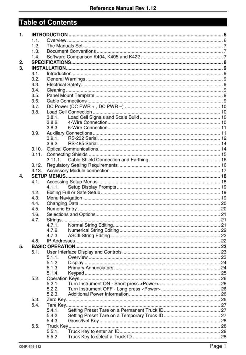
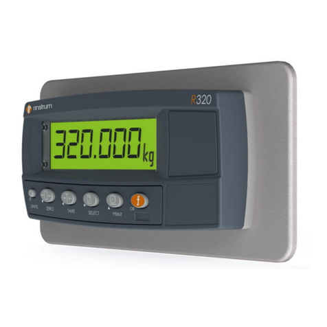
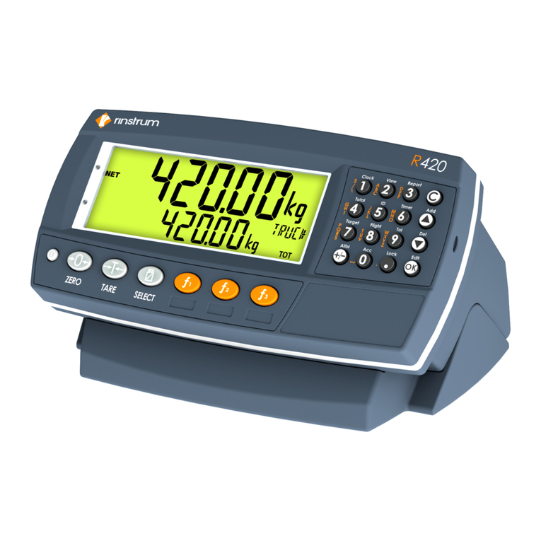
Rinstrum 400 Series User manual

400 Series
(K481)
Summing Indicator
OperatorManual
RI00-618-100

Copyright
All RightsReserved.Nopartofthisdocument maybe
copied,reproduced, republished, uploaded, posted,
transmitted, distributed,stored inor introduced intoa
retrievalsysteminanyform, or byanymeans(electronic,
mechanical,photocopying, recording or otherwise)
whatsoever without prior written permission of Rinstrum
PtyLtd.
Disclaimer
RinstrumPtyLtdreservestheright tomakechangesto
the productscontained inthismanualinorder toimprove
design,
performanceorreliability.
The information inthismanualisbelieved tobe accurate
inall respectsatthetimeof publication, but issubjectto
change without notice.RinstrumPtyLtdassumesno
responsibilityfor anyerrorsoromissionsand disclaims
responsibilityfor anyconsequencesresultingfromtheuse
of theinformation provided herein.

Operator Manual - Software Version 1.x & 2.x
Page 1 004R-601-170
Table of Contents
1. INTRODUCTION...................................................................2
2. SAFETY ................................................................................3
2.1. Operating Environment ...............................................3
2.2. Electrical Safety ..........................................................3
2.3. Cleaning ......................................................................3
3. BASIC OPERATION.............................................................4
3.1. User Interface Display and Controls ...........................4
3.2. Basic Operation...........................................................8
3.3. Stability Considerations............................................ 10
3.4. Security .................................................................... 10
4. ADDITIONAL FUNCTIONS............................................... 11
4.1. Product Selection ..................................................... 11
4.2. Add Product ............................................................. 11
4.3. Delete Product ......................................................... 12
4.4. Rename Product ...................................................... 12
4.5. Clock ........................................................................ 12
4.6. View ......................................................................... 13
4.7. Report ...................................................................... 13
4.8. Totals ....................................................................... 14
4.9. IDs............................................................................ 14
4.10. Targets ..................................................................... 15
4.11. Lock.......................................................................... 15
4.12. Acc ........................................................................... 15
5. FUNCTION KEYS.............................................................. 17
5.1. Introduction .............................................................. 17
5.2. Print.......................................................................... 17
5.3. Single ....................................................................... 18
5.4. Test .......................................................................... 18
5.5. Prd.Sel ..................................................................... 19
5.6. SLAVE...................................................................... 20
6. ERROR MESSAGES......................................................... 21
6.1. Weighing Errors ....................................................... 21
6.2. Summing Errors ....................................................... 22

Operator Manual - Software Version 1.x & 2.x
Page 2 004R-601-170
1.Introduction
This precision digital summing indicator can sum up to nine
slave indicators. The summing indicator will show an error
message (------) if any of the slave weights are negative or if
there is a mix of gross and net weights, as defined by Technical
Schedule S1/0/A.
Facilities are provided to view and use individual slave weights
and sub totals of a subset of the slave weights. Zero and Tare
functionality as well as pluggable modules and battery backed
clock/calendar, special function keys (for printing and slave
weights, etc).

Operator Manual - Software Version 1.x & 2.x
Page 3 004R-601-170
2.Safety
2.1. Operating Environment
•Operating Temperature: –10 to 50°C
•Humidity: <90% non-condensing
•Operating Voltage: Shown on Rear Label
2.2. Electrical Safety
•For your protection all mains electrical hardware must be
rated to the environmental conditions of use.
•Pluggable equipment must be installed near an easily
accessible power socket outlet.
•To avoid the possibility of electric shock or damage to the
instrument, always switch off or isolate the instrument from
the power supply before maintenance is carried out.
2.3. Cleaning
•To maintain the instrument, never use harsh abrasive
cleaners or solvents. Wipe the instrument with a soft cloth
slightly dampened with warm soapy water.

Operator Manual - Software Version 1.x & 2.x
Page 4 004R-601-170
3.Basic Operation
3.1. User Interface Display and Controls
Overview
Code Description
1 Display
2 Numeric Keypad
3 Function Keys (user defined)
4 Function Keys (Fixed)
5 Power Key

Operator Manual - Software Version 1.x & 2.x
Page 5 004R-601-170
Display
Code Description
1 Primary Annunciators
2 Primary Display
3 Auxiliary Display
4 Primary Units
5 Secondary ID
6 Miscellaneous Annunciators
7 Secondary Units
8 Secondary Display

Operator Manual - Software Version 1.x & 2.x
Page 6 004R-601-170
Primary Annunciators
Symbol Name Description
HOLD Visible when the displayed reading is
held.
NET Visible when the displayed reading
represents Net weight.
ZERO Visible when the gross reading is within ±
¼ of a division of true zero.
MOTION Visible when the displayed reading is not
stable.
ZERO
BAND
Visible when the displayed weight is within
the zero 'dead' band setting.
RANGE Indicates current range (for dual range/interval).

Operator Manual - Software Version 1.x & 2.x
Page 7 004R-601-170
Keypad
Code Description
1 Numeric
Button
0-9
2 White Characters Additional Functions (Hold 2 seconds)
3 Orange
Characters
(Alpha and Symbols)
Cancel Undo last command; step backwards
(including in menus).
Up Move cursor backwards; previous option
Down Move cursor forwards; next option
OK Accept this choice
Decimal Point Place decimal point
+/- Change to negative or positive number;
access or exit Alibi

Operator Manual - Software Version 1.x & 2.x
Page 8 004R-601-170
3.2. Basic Operation
Power Key
ON Instrument
OFF Instrument
Zero Key

Operator Manual - Software Version 1.x & 2.x
Page 9 004R-601-170
Tare Key
Gross/Net Key

Operator Manual - Software Version 1.x & 2.x
Page 10 004R-601-170
3.3. Stability Considerations
Some functions (E.g. Tare and Zero) require a stable
weight. These functions will wait for up to 10 seconds for
stable weight.
3.4. Security
Most functions can be locked in setup. The locking options
are:
•Disabled
•Operator Passcode required
•Safe Setup Passcode required
•Enabled
Operator Passcodes only need to be entered once. The
system can be locked using the Lock key.

Operator Manual - Software Version 1.x & 2.x
Page 11 004R-601-170
4.Additional Functions
4.1. Product Selection
4.2. Add Product

Operator Manual - Software Version 1.x & 2.x
Page 12 004R-601-170
4.3. Delete Product
4.4. Rename Product
4.5. Clock

Operator Manual - Software Version 1.x & 2.x
Page 13 004R-601-170
4.6. View
4.7. Report

Operator Manual - Software Version 1.x & 2.x
Page 14 004R-601-170
4.8. Totals
4.9. IDs

Operator Manual - Software Version 1.x & 2.x
Page 15 004R-601-170
4.10. Targets
(1) (2) (3)
(4)
(5)
(Setpoint Targets)
OK
123
456
789
0
OK
Target
7
4.11. Lock
4.12. Acc

Operator Manual - Software Version 1.x & 2.x
Page 16 004R-601-170
M4221 Ethernet Module

Software Version 1.1x & 2.x
Page 17 004R-624-110
5.Function Keys
5.1. Introduction
The instrument has 3 function keys.
External keys can also be used. The
function of the keys can be configured
to any of the functions detailed below
5.2. Print

Software Version 1.1x & 2.x
Page 18 004R-624-110
5.3. Single
5.4. Test
Other manuals for 400 Series
7
This manual suits for next models
1
Table of contents
Other Rinstrum Accessories manuals

Rinstrum
Rinstrum R323 Use and care manual

Rinstrum
Rinstrum 400 Series User manual

Rinstrum
Rinstrum K404 User manual

Rinstrum
Rinstrum 1203 User manual

Rinstrum
Rinstrum X300 IP69K376 User manual

Rinstrum
Rinstrum 5100 Use and care manual

Rinstrum
Rinstrum R320 User manual

Rinstrum
Rinstrum K410 User manual

Rinstrum
Rinstrum K404 User manual