Rinstrum 5100 Use and care manual

5100
Digital Indicator
CommunicationsManual
For use withSoftwareVersions3.0and above
5100-602-320

Rinstrum5100 -CommunicationsManual–5100-602-320
2
Table of Contents
1. INTRODUCTION..........................................................................................................4
2. CONNECTIONOF THE5100 NETWORK....................................................................5
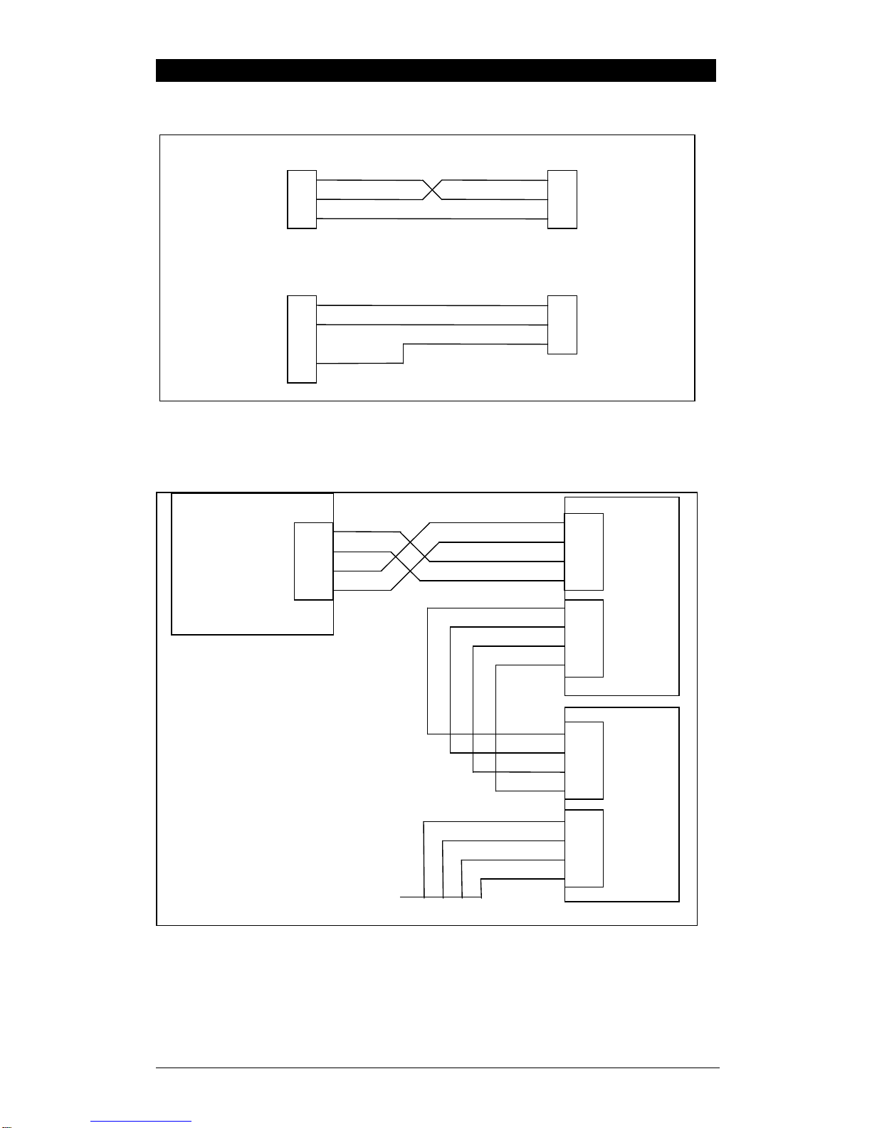
2.1 RS232 CONNECTION......................................................................................................... 5
2.2 RS485/RS422 CONNECTION.............................................................................................. 5
3. COMMAND OVERVIEW...............................................................................................6
3.1 COMMANDSAND QUERIES................................................................................................. 6
3.2 RESPONSES....................................................................................................................... 6
3.3 PARAMETERS.................................................................................................................... 6
3.4 TERMINATION................................................................................................................... 6
3.5 TRADE COUNTER:............................................................................................................. 6
4. COMMAND DETAILS...................................................................................................7
4.1 ADR SET ADDRESS ..................................................................................................... 7
4.2 AFT AUTO OUTPUT FORMAT............................................................................................. 8
4.3 ASF SET FILTERING..................................................................................................... 8
4.4 BAT BATCHCONTROL................................................................................................. 9
4.5 BDR SET BAUD RATE................................................................................................ 10
4.6 CDL SET ZERO............................................................................................................ 10
4.7 CLK SET CLOCK......................................................................................................... 11
4.8 COF SET OUTPUT FORMAT....................................................................................... 11
4.9 CWT SET CALIBRATION WEIGHT........................................................................... 13
4.10 ENUSET UNITS........................................................................................................... 13
4.11 ESR? QUERY STATUS................................................................................................. 14
4.12 FNC FUNCTION KEYSETTING.................................................................................. 15
4.13 FOP FORCE OUTPUT................................................................................................... 15
4.14 IAD SET SCALE BUILD............................................................................................... 16
4.15 ICRSET MEASUREMENT RATE................................................................................ 17
4.16 IDN SET IDENTIFICATION......................................................................................... 17
4.17 LBT BUTTON LOCK SETTINGS ................................................................................. 18
4.18 LDW CALIBRATE ZERO DEAD WEIGHT................................................................. 18
4.19 LIC LINEARISATION.................................................................................................. 20
4.20 LIM MATERIAL SETTINGS ....................................................................................... 21
4.21 LIR RECIPE SETTINGS............................................................................................... 21
4.22 LIS GENERAL SETPOINT SETTINGS......................................................................... 22
4.23 LIT SET TARGET VALUE........................................................................................... 23
4.24 LIV SETPOINT SETTINGS.......................................................................................... 23
4.25 LOG? RECIPE &MATERIAL LOGS............................................................................ 25
4.26 LWT CALIBRATE SPAN.............................................................................................. 26
4.27 MSV? QUERY MEASUREDWEIGHT VALUE............................................................ 27
4.28 MTDMOTION SETTINGS........................................................................................... 28
4.29 PCD ENTERPASSCODE............................................................................................. 28
4.30 PCE SET COUNTING SAMPLE................................................................................... 29
4.31 PFT PRINTED TICKET OUTPUT FORMAT ........................................................................... 29
4.32 PRS PRINTER\SERIAL 2SETTINGS........................................................................... 30
4.33 PRT PRINT................................................................................................................... 30
4.34 PST SET PRINTERHEADERS..................................................................................... 32
4.35 RBT REMOTE BUTTON SETTINGS .................................................................................... 32
4.36 REC SET CURRENT RECIPE....................................................................................... 33
4.37 RESRESET................................................................................................................... 34
4.38 STPSTOP CONTINUOUS TRANSFER........................................................................ 34
4.39 SXX SELECT UNIT....................................................................................................... 34
4.40 TAR TARE................................................................................................................... 35
4.41 TAS GROSS /NET ....................................................................................................... 35
4.42 TAV SET TARE VALUE.............................................................................................. 36
4.43 TDD LOAD/SAVE SETUP............................................................................................ 36
4.44 VAL? MV/VVALUEQUERY ............................................................................................ 36
4.45 WMD SET WEIGHING MODE..................................................................................... 36
4.46 ZST ZERO SETTINGS................................................................................................. 38
5. COMMAND SUMMARY..............................................................................................39

Rinstrum5100 -CommunicationsManual–5100-602-320
3
5.1 SET COMMUNICATION PARAMETERS................................................................................ 39
5.2 SET SCALE BUILD ........................................................................................................... 39
5.3 CALIBRATION ................................................................................................................. 39
5.4 SET SCALE OPTIONS........................................................................................................ 39
5.5 BATCHING SETTINGS....................................................................................................... 39
5.6 GENERAL COMMANDS..................................................................................................... 40
5.7 QUERIES......................................................................................................................... 40
5.8 TEST COMMANDS............................................................................................................ 40
5.9 COMMON COMMANDS..................................................................................................... 40

Rinstrum5100 -CommunicationsManual–5100-602-320
4
1.Introduction
Thismanualdetailsthe extended communicationsprotocolof the 5100.
Asimpledirectprotocolthatmimics the pressing ofthe frontpanelkeys is
described inthe referencemanual.
The extended protocolallowsforcompletecalibration and controlofamulti-
drop networkofup tothirty-two5100 units.Thisprotocolisused bythe
Viewer98 programtocalibrateand configurethe 5100 units.Usethe TEST
page asaconvenient terminaltotest the 5100 communications.
Thismanuallistsall ofthe commandsforthe extended protocolin
alphabeticalorder.Inpracticeonlyasmall subset of thesecommandswould
be used tocontroloperationalparameters.
The command summaryatthe end ofthe manualgroupscommandsinto
related functions.

Rinstrum5100 -CommunicationsManual–5100-602-320
5
2. Connection ofthe5100 Network
2.1RS232 Connection
Figure1:Connection ofasingle5100 unittoan IBMPCeitherusing COM1
orCOM2on the PC.
2.2RS485/RS422 Connection
Figure2: Connection of aRS485/RS422 network.
To5100
SERIAL
1
To5100
SERIAL
1
2RXD
3TXD
5GND
2TXD
3RXD
7GND
PC
COM1
DB9
PC
COM2
DB25
2RXD
3TXD
5GND
2RXD
3TXD
5GND
RA
RB
TA
TB
RA6
RB7
TA8
TB9
SERIAL
1
SERIAL
2
TO NEXTUNIT
SERIAL
1
SERIAL
2
UNIT1
UNIT2
RA6
RB7
TA8
TB9
RA6
RB7
TA8
TB9
RA6
RB7
TA8
TB9
RS485/RS422
HOST

Rinstrum5100 -CommunicationsManual–5100-602-320
6
3.Command Overview
3.1Commandsand Queries
Acommand consistsof three ASCII-characters(eg IDN).
AqueryconsistsoffourASCII charactersand endswithaquestion
mark(e.g. IDN?).
3.2Responses
The 5100 respondswith0CRLF toindicatethatacommand hasbeen
accepted or?CRLF toindicatethatthe command waseithernot
understood orcouldnot be performed.
Specificqueriescausethe 5100 torespond withthe datarequested by
the query.(e.g.The 5100 wouldrespond with4 CRLF toaADR?
Queryif it wassetup withaddress 4)
3.3Parameters
Acommand orquerycan be followed byone ormoreparameters.
Parametersareeithernumeric(e.g. 3000)orstrings(e.g. “Fred”).
String parametersaredelimited byquotecharacters(‘“’ASCII 34).
Theyaretaken literallysothat “AbCd”isnot the sameas“abcd”.
Numericparametersarevariableand leading and trailing spacesare
ignored. Asaresult 003 03 and 3areidentical.
Parametersareseparated bythe commasign (‘,’ASCII 44).
Parametersmaybe left outcompletelysothatitispossibletochange
one parameterwithoutaltering the others.ForexampleIAD1,,2;will
change the position of the decimalpoint only.
3.4Termination
Termination charactersaresenttodefine the end of acommand, query
orresponse.
Permissibletermination charactersare‘;’(ASCII 59), LF (ASCII 10),
CRLF (ASCII 13 10),LFCR (ASCII 10 13).E.g.ADR?;isthe sameas
ADR? CRLF
The 5100 always uses CRLF asthe termination of itsresponses.
3.5TradeCounter:
All trade relevantfunctionsareguarded bythe trade counter.Thereis
no differenceinchanging settingsviathe communicationsinterfaceor
viathe frontpanel.If the counterreaches60000 the 5100 operation is
blocked and it must be returned tothe factory.
Notethatthe 5100 doesnotcheck tosee ifnewdataisdifferentfrom
the olddatabeforeincrementing the Trade Counter,sosending
IAD1,6000 will incrementthe countereven ifthe 5100 issetup witha
fullscaleof 6000 kgalready.
It ispossibletoblock all changestotrade relevantparametersby
setting aFull Setup Passcode.If suchapasscode hasbeen settrade
parameterscan onlybe changed viathe serialportafteraPCD
command hasbeen sent withthe correct passcode.

Rinstrum5100 -CommunicationsManual–5100-602-320
7
4.Command Details
4.1ADR SETADDRESS
Set the address of aunit.
General
No. of parameters 2
Savechanges. withTDD1
Increment Trade Counter No
ParameterDetails
Parameter Description Range Default
1 Address 0.. 31 31
2 SerialNumber “0000001”
.. “9999999” “xxxxxxx”
factoryset
Each5100 mustbe assigned aunique address toenablethe implementation
ofamulti-drop network.Thisaddress can be setusing the digitalsetup
menusasdescribed inthe ReferenceManual.It isalsopossibletousethe
networkitselftosetthe unitaddresses.The ADDRESS COMMAND isused
toassign the unit address viathe communicationsnetwork,
Beforethe address ofaunitcan be changed the unitmustbe selected to
respond tocommands.The SELECTCOMMAND (see Sect4.39 pg 34)is
used toselectaunit. If the currentaddress ofthe unitisknownusethisto
selectthe unit, ifnotissue the S99;command toselectall units.To
distinguishbetween unitsofthe sameaddress usethe serialnumber
parameterofthe ADDRESS COMMAND.The serialnumberisunique to
eachunitand onlythe unitwiththe matching serialnumberwill respond to
the ADDRESS COMMAND.If neitherthe currentaddress norserialnumber
ofthe unitsisknown,turnoff all the unitsinthe networkand then turnon one
unitatatime.The combination ofS99;and ADR command will then allow
eachunit tobe configured.
Example1:
Change address of unit from1to2
S01;Select unit 1
ADR2; 0 CRLF Set address to2
TDD1; 0 CRLF Savechange
S02; Select newunit 2
IDN?; WE,”WE2110”,”123456”,P50 CRLF
Ask forID
Example2:
Twounitswithunknownaddressesareconfigured using theirserialnumbers.
S99;
ADR01,”123456”;0 CRLF Unit withserialno. “123456”
getsaddress 01
ADR02,”123457”;0 CRLF Unit withserialno. “123457”
getsaddress 02
S01;TDD1;
S02;TDD1; 0 CRLF
0 CRLF Saveaddressesagainst
powerloss
S01; Select the newunit 1
IDN?; ””,”123456”,"V1.5","5100"
CRLF Ask forID

Rinstrum5100 -CommunicationsManual–5100-602-320
8
4.2AFT AutoOutputFormat
Alterthe format string forthe autotransmit output.
General
No. of parameters 1
Savechanges. WithTDD1
Increment Trade Counter No
ParameterDetails
Parameter Description Range Default
1 Format String
(up to20 chars) “String” “”
Example:
S01;Select unit 1
AFT?; “”CRLF Current format isnull
PRS1,,,,,6; 0 CRLF SetSer2toautotransmit
using the autoformat string.
AFT”\201\210 \211”; 0 CRLF Newautooutputwouldlook
like: 127.8kgG
TDD1; 0 CRLF savesettings.
See ReferenceManualfordetailson the autoformat string.
4.3ASFSETFILTERING
Set the filtering characteristics of aunit.
General
No. of parameters 2
Savechanges. withTDD1
Increment Trade Counter No
ParameterDetails
Parameter Description Range Default
1 Numberof consecutive
readingstoaverage 0
…
9
10
11
12
13
14
1
…
10
25
50
75
100
200
9
2 Anti-JitterSetting 0
1
2
off
fine
coarse
0
Example:
S01;Select unit 1
ASF?; 9,0CRLF Queryfiltering setting
ASF4,1; 0 CRLF Changed toa5reading average withfine
anti-jittersetting.
TDD1; 0 CRLF Savenewsettings.

Rinstrum5100 -CommunicationsManual–5100-602-320
9
4.4BATBATCH CONTROL
Allowsremotecontrolof batching and running statusof batching tobe read.
General
No. of parameters 6
Savechanges. -
Increment Trade Counter -
ParameterDetails
Parameter
Description Range Default
p1 Replytype 1
2
3
Start
Pause
Abort Batch
-
QueryDetails
Parameter Description Range
r1 Batching Status 0
1
2
Idle
Running
Paused
r2 Current Recipe 0
1..99 Not Running
Current Recipe
r3 Current Materialbeing Filled 0
1..20 Not Filling
Current Material
r4 MaterialTarget being Filled 0.. Fullscale
r5 Statusof all 24 setpoints “000000”to“FFFFFF”
(output 1isrightmost
eg "000001")
Example:
CommandReply Result
REC (See RECcommand
instructionstoselectrecipe and
proportion beforestarting the
batch)
BAT?; 0,0,0,0,"000000" CRLF Batching idle
BAT1; 0 CRLF Start batchwithcurrent recipe
BAT? 1,5,1,1000,"000001" CRLF Batching running,
Recipe 5
Material1: 1000 kg
Output 1active
BAT2; 0 CRLF PauseBatch
BAT?; 2,5,1,1000,"000000" CRLF Batching paused
BAT1; 0 CRLF Continue Batching
BAT?; 1,5,2,500,"000002" CRLF BatchRunning
Recipe 5
Material2: 500 kg
Output 2active

Rinstrum5100 -CommunicationsManual–5100-602-320
10
4.5BDR SETBAUD RATE.
Set the communication parameters, baud rate, parityetc.
General
No. of parameters 4
Savechanges. withTDD1
Increment Trade Counter no
ParameterDetails
Parameter Description Range Default
1 Baud Rate 1
2
3
4
5
6
7
300
600
1200
2400
4800
9600
19200
6
2 Parity 0
1
2
none
odd
even
0
3 DataBits 7,8 8
4 Stop Bits 1,2 1
5 Termination Resistors 0
1 OFF
ON 0
Example:
S01;Select unit 1
BDR?; 6,0,8,1,0 CRLF Querybaud ratesetting
BDR4,1,7,1,1;0 CRLF(Notethatthe
replyissentusing the new
settings)
Settingschanged to2400
baud,odd parity,7databits,
1stop bit, termination on.
TDD1; 0 CRLF Savenewsettings.
4.6CDLSETZERO.
Setthe zerodead load cancellation.Thisisanalogouswithpressing the
ZERO keyon the front of the instrument.
General
No. of parameters 0
Savechanges. At input
Increment Trade Counter no
If the Setzerooperation isnotpossibledue tothe value ofthe currentweight
reading ordue toinstabilitythe 5100 will return‘?’.
Example:
S01;Select unit 1
CDL; 0 CRLF Zerodead load set successfully.
<load disturbed>
CDL; ? CRLF Setting ofzerodead load notpossibledue
tomotion, errorordead load range.

Rinstrum5100 -CommunicationsManual–5100-602-320
11
4.7CLKSETCLOCK
Set the timeand date.
General
No. of parameters 6
Savechanges. At input
Increment Trade Counter no
ParameterDetails
Parameter Description Range Default
1 Hour 0..23 -
2 Minute 0..59 -
3 Second 0..59 -
4 Date 1..31 -
5 Month 1..12 -
6 Year* 1998..2098 -
Example:
S01;Select unit 1
CLK?; 9,20,10,16,2,1999
CRLF Querycurrent time&date
CLK10,0,0,17,2,2001; 0 CRLFChange to10 am23/6/2001
CLK10,0,0,17,2,01; 0 CRLF Sameasabove
•The Yearmaybe set eitherin2digit or4digit format. The instrument will
convert thistoa4digit yearautomatically. E.g. 2/2/1isconverted to
2/2/2001.
4.8COFSETOUTPUTFORMAT.
Set the output format of the MSV?Query.
General
No. of parameters 1
Savechanges. withTDD1
Increment Trade Counter no
Parameter Details
Parameter Description Range Default
1 Format setting 0..11 6
Binary Formats
Format Data Order
0 4 Byte(binary)CRLF MSB beforeLSB(=00h)
2 2 Byte(binary)CRLF MSB, LSB
4 4 Byte(binary)CRLF LSB(=00h)beforeMSB
6 2 Byte(binary)CRLF LSB, MSB
8 4 Byte(binary)CRLF MSB beforeLSB (=Status)
ASCII Formats
Format Parameter
1 Parameter
2 Parameter3
1&3 Weight (8) CRLF
5&7 Weight (8) , Address (2) CRLF
9&10 Weight (8) , Address (2) , Status(3)CRLF
11 Weight (8) , Address (2) , Extended
Status(3) CRLF

Rinstrum5100 -CommunicationsManual–5100-602-320
12
Valuesinbracketssignifythe numberofcharactersinthe fixed length
response.
The weightformatisthe sign (spaceorminus),followed by7digits0..9
including the decimalpoint if used.
The binaryformatsareusefulforPLCcommunicationsinapplicationswhere
conversion of the ASCII weight string isnot possible. The binaryoutputscan
generallybe used directlybythe PLC.
STATUS Details
Status Description Bit Comment
001 Overload 0 Weight reading out of
range overload or
underload
002 Standstill 1
004 Gross 2
008 Range 2active 3 Onlywithmulti-range or
multi-interval
016 Output 1active 4
032 Output 2active 5
064 Output 3active 6
128 Output 4active 7
256 Centreof Zero8 Thisstatusbit isonly
availableinthe extended
status-Format 11 only.
Notethatthe statusbitsareadded together,forexampleastatusof6(4+2)
meansthe weightreading isaGross value withno motion,range 1,and all
limit valuesareinactive.
Example1:
S01;Select unit 1
COF?;3 CRLF Queryformat
MSV?;-00001.0 CRLF Queryweight reading.
COF9;0 CRLF Change toformat 9
TDD1;0 CRLF savenewsetting
MSV?;-00001.0,01,006 CRLF
Queryweight reading.
Example2: Useof Binaryformat forPLCuse
Initialisation
S01;Select unit 1
COF8; 0 CRLF Set format 8
TDD1; 0 CRLF Saveformat setting
PLCOperation
MSV?; CRLF Queryweightreading using the newforma
t.
Inthisexamplethe weightisastablegross
reading of 1000 kg.
COF8replieswith
<24 bitsof weight><8bit status><CRLF>
the hexadecimalvaluesofthe returned data
are<00><01><E8><06><0C><0A>butthis
dataisnot printabledirectly.

Rinstrum5100 -CommunicationsManual–5100-602-320
13
4.9CWTSETCALIBRATIONWEIGHT.
Setthe calibration weighttobe used forspan calibration.Thismustbe set
beforeusing the LWT; span calibration command.
General
No. of parameters 1
Savechanges. withTDD1
Increment Trade Counter no
ParameterDetails
Parameter Description Range Default
1 Calibration Weight 2%-100%of full
scaleweight.
(Send IAD?to
read full scale
setting)
3000
Example:
S01;Select unit 1
CWT?; 3000 CRLF Querycalibration
weight setting
CWT4000; 0 CRLF
(Notethatweightissentwithout
anydecimalpoint. So400.0kgis
send as4000 not 400.0)
Change calibration
weight to4000.
TDD1; 0 CRLF Savenewsetting.
4.10 ENU SETUNITS
Set the unitsof weight tobe displayed and printed.
General
No. of parameters 1
Savechanges. withTDD1
Increment Trade Counter yes
Parameter Details
Parameter Description Range Default
1 Weight units 0
1
2
3
4
none
g
kg
lb
t
2
Example:
S01;Select unit 1
ENU?; 2 CRLF Queryunitssetting.
ENU1; 0 CRLF Change unitstograms
TDD1; 0 CRLF Savenewsetting.

Rinstrum5100 -CommunicationsManual–5100-602-320
14
4.11 ESR?QUERYSTATUS
Querythe errorstatusof the instrument.
General
No. of parameters 1
ParameterDetails
Parameter Description Range Default
1 select type of statusinformation 0..1 0
The 5100 containsbothcurrentand latched errorstatusflags.The latched
errorsareonlycleared byresetting the unit(RES command orpoweroff).
The statusstring is4hexadecimalcharactersrepresenting the 16 errorbits.
ErrorDescription
0001 The powersupplyvoltage istoo low.
(check supply)
0002 The powersupplyvoltage istoo high.
(check supply)
0004 The load cell excitation voltage istoo low.
(check scale/supply)
0008 The load cell excitation voltage istoo high.
(check scale/supply)
0010 The temperatureisoutside of allowablelimits.
(check location)
0020 Scalebuildisincorrect. The numberof graduationshas
been set <100 or>100000.(fixup scalebuild)
0040 The positivesenseline isnot connected.
(check connection)
0080 The negativesenseline isnot connected.
(check connection)
0100 The digitalsetup information hasbeen lost.
(re-entersetup)
0200 The calibration information hasbeen lost.
(re-calibrate)
0400 The factoryinformation hasbeen lost.
(service)
0800 The EEPROMmemorystorage chiphasfailed
(service)
2000 The Internalclock chiphasfailed. (service)
8000 The EPROMmemorystorage chiphasfailed. (service)
The statusbitsareadditive.Forexampleifacondition isdetected wherethe
powersupplyvoltage islow,resulting inareduction ofexcitation voltage,the
resulting statussetting will be 0005 (0001 +0004).The numbersadd in
hexadecimalasfollows:-
1-2-3-4-5-6-7-8-9-A-B-C-D-E-F
(Forexample, 2+4=6, or4+8=C)
ESR?Example:
S01;Select unit 1
ESR?; 0000 CRLF Nocurrent errors.
ESR?1; 00C0 CRLF Positiveand NegativeSenselineswerenot
connected at sometimeinthe past.

Rinstrum5100 -CommunicationsManual–5100-602-320
15
4.12 FNC FUNCTIONKEYSETTING
Alterthe roleof the front panelfunction key.
General
No. of parameters 1
Savechanges. WithTDD1
Increment Trade Counter No
ParameterDetails
Parameter Description Range Default
1 Function Setting 0
1
2
3
4
5
6
7
8
9
None
Start
Pause
Batch
Auto/Manual
ManualHold
PeakHold
Livestock Hold
Count
ShowTotal
0
Example:
S01;Select unit 1
FNC?; 0 CRLF Function Keyset to'NoFunction'.
FNC3; 0 CRLF Set function to.
TDD1; 0 CRLF savesetting.
4.13 FOPFORCEOUTPUT
Usethiscommand toforcea5100 outputeitheron oroff. Thisisonly
availablefor5100 outputsthataresetup withno otherfunction.Usethe
querytoobtainthe stateof the first six5100 outputs.
General
No. of parameters 6
Savechanges. -
Increment Trade Counter -
ParameterDetails
Parameter Description Range
1 Output 1 0 foroff, 1foron
2 Output 2
3 Output 3
4 Output 4
5 Output 5
6 Output 6
Example:
S01;Select unit 1
FOP?; 0,0,0,1,0,0 CRLF Output 4ison the othersareoff
FOP,,1; 0 CRLF DriveOutput 3on
FOP,,0; 0 CRLF Driveoutput 3off

Rinstrum5100 -CommunicationsManual–5100-602-320
16
4.14 IADSETSCALEBUILD
Set the scalebuildparametersincluding max1,e1,max2,e2,decimalpoint etc.
General
No. of parameters 5
Savechanges. WithTDD1
Increment Trade Counter Yes
ParameterDetails
Parameter Description Range Default
1 Range 1..2 1
2 NominalLoad
(max1ormax2) 100 .. 999999 Range 1: 3000
Range 2: 6000
3 No. of right side digits.
(decimalpoint
position)
0..5 0
4 Resolution (e1 ore2) 1
2
3
4
5
6
7
1
2
5
10
20
50
100
Range 1: 1
Range 2: 2
5 X10 mode 0
1 off
on 0
Notethatthe full scaleweightofthe instrumentissettoNominalLoad 1for
singlerange installations,and NominalLoad 2fordual-range and dual-
intervalinstallations.Insinglerange installationsNominalLoad 2isnot
used.
Example:
S01;Select unit 1
IAD?1; 1,3000,0,1,0 CRLF
IAD1,4000,1,2,0;
0 CRLFmax1=4000,e1 =2with1
digitafterdecimalpointon
range 1. x10 mode isoff.
TDD1; 0 CRLF savesetting.
If IAD?isissued withoutthe range parameterthen the returned dataisrange
1forsinglerange setup orrange 2fordualintervalordualrange setup.In
thiswayitispossibletoquerythe maximumload withoutthe need toissue a
WMD?Command todetermine the weighing mode.

Rinstrum5100 -CommunicationsManual–5100-602-320
17
4.15 ICR SETMEASUREMENTRATE
Set the fundamentalmeasurement frequency of the instrument.
General
No. of parameters 1
Savechanges. WithTDD1
Increment Trade Counter yes
ParameterDetails
Parameter Description Range Default
1 Measurement Ratein
Hz. 15-60 50
Example:
S01;Select unit 1
ICR?; 50 CRLF Querycurrentmeasurement
rate
ICR60; 0 CRLFChange to60 Hz
TDD1; 0 CRLF savesetting.
4.16 IDN SETIDENTIFICATION
Set the unit identification string.
General
No. of parameters 1
Savechanges. WithTDD1
Increment Trade Counter no
ParameterDetails
Parameter Description Range Default
1
Identification string.
(15 bytesmax). “string ” “WE2110”
2 SerialNumberstring “000000”
..
“999999”
factoryset,
unique toeach
unit
3 Version string P50 -P59
Notethatonlythe identification string maybe changed.The serialnumber
and version arefixed atthe factoryand areavailableforinformation onlyby
using the IDN?Query.
Example:
S01;Select unit 1
IDN?; WE”WE2110”,”123456”,P52HCRLF Querycurrent
identification.
IDN”SiteA”; 0 CRLFChange
identification
string to
“SiteA”
TDD1; 0 CRLF savesetting.

Rinstrum5100 -CommunicationsManual–5100-602-320
18
4.17 LBTBUTTONLOCK SETTINGS
Set the operation statusof eachof the 4front panelbuttons.
General
No. of parameters 2
Savechanges. WithTDD1
Increment Trade Counter no
ParameterDetails
Parameter Description Range Default
1
Button 0
1
2
3
ZERO
TARE
GROSS/NET
PRINT
0
2 Operation 0
1
2
LOCK
NORMAL
IMMEDIATE
1
Operation ofeachofthe 4frontpanelbuttonsmaybe setindependently.
NORMALisobviouslythe normalfunction ofthe button.LOCKmeansthat
the button islocked and its’normaloperation isblocked.IMMEDIATEallows
forthe button function tooperatewithout waiting forstablereadings.
Example:
S01;Select unit 1
LBT0?; 1 CRLF ZERO iscurrentlyset toNORMALOperation
LBT0,0; 0 CRLF Block operation of the ZERO button
TDD1; 0 CRLF savesetting.
4.18 LDWCALIBRATEZERO DEADWEIGHT
It ispossibletocalibratethe zerodead weighteitherwithno load on the
scalebaseorthe calculated mV/Vsignalmaybe entered directly.
General
No. of parameters 0(1if using direct mV/Vcal)
Savechanges. WithTDD1
Increment Trade Counter yes
a)CalibrationwithWeight
Thistype of calibration isused withWeighing Modes1,2&3(See WMD
command).
The calibration process takessometimetocomplete.Asaresultitis
necessarytomonitorthe calibration process todetermine when itisfinished.
Todo thisissue aLDW?Query.Following isalistofthe possiblecalibration
statusresponses.
CalibrationStatus
StatusValue Description
0 Calibration finished successfully
1 Calibration inprocess (Busy)
101 ErrorZerotoo high (>2mV/V),
Calibration aborted.
102 ErrorZerotoo low(<-2mV/V),
Calibration aborted.

Rinstrum5100 -CommunicationsManual–5100-602-320
19

Rinstrum5100 -CommunicationsManual–5100-602-320
20
Example:
S01;Select unit 1
LDW; 0 CRLF Start zerocalibration.
LDW?; 1 CRLF Querystatusof the zerocalibration process
LDW?; 1 CRLF Still busy
LDW?; 0 CRLF Zerocalibration finished
TDD1; 0 CRLF Savesetting.
b)DirectmV/Vcalibration
When using direct mV/Vcalibration the mV/Vsignallevelisentered directly.
ParameterDetails
Parameter Description Range Default
1
Dead load signalinmV/V.
20000 =2.0mV/V -20000..20000 0
Example:
S01;Select unit 1
VAL?; 5076CRLF Current reading is0.5076 mV/V
LDW5076; 0 CRLF Set zerodead load to0.5076mV/V.
LDW?; 5076CRLF Zerodead load is0.5076mV/V
TDD1; 0 CRLF savesetting.
4.19 LICLINEARISATION
Thiscommand givesaccess tothe multi-pointlinearisation functionsofthe
5100. AspecialqueryLIC?isavailabletoverifythe linearisation correction.
General
No. of parameters 2
Savechanges. WithTDD1
Increment Trade Counter yes
ParameterDetails
Parameter Description Range Default
1 Linearisation Point 1..5 1
2 Test Weight Value 0..999999 -
QueryDetails
Parameter Description Range
1 Percentage of Full Scalereading -100..100
2 Correction (inweight unitsx10) -100000 .. 100000
Toclearone of the Linearisation pointsleavethe test weight value off.
Example:ScaleBuildismax1 =500.0kg, e1 =0.1kg
S01;Select unit 1
LIC1; 0 CRLF ClearLinearisation Point 1.
LIC?1; 0,0 CRLF Nocorrection forpoint 1
MSV?; 120.5 CRLF
LIC1,1200;0 CRLF SetLinearisation Point1tocorrectforthe
current test weight of 1200 kg.
(Notethatweightissentwithoutanydecimal
point. So400.0kgissent as4000 not 400.0)
LIC?1; 24,-50 CRLF
Currentlinearisation isapprox.-5.0kgat24%
of fullscalereading.
TDD1; 0 CRLF Savesetting.
Table of contents
Other Rinstrum Accessories manuals

Rinstrum
Rinstrum R320 User manual

Rinstrum
Rinstrum R323 Use and care manual

Rinstrum
Rinstrum K404 User manual

Rinstrum
Rinstrum 400 Series User manual

Rinstrum
Rinstrum K410 User manual

Rinstrum
Rinstrum K404 User manual

Rinstrum
Rinstrum X300 IP69K376 User manual

Rinstrum
Rinstrum 400 Series User manual

Rinstrum
Rinstrum 1203 User manual
Popular Accessories manuals by other brands

KROHNE
KROHNE OPTIMASS 3000 Handbook

PCB Piezotronics
PCB Piezotronics 4106-01A Installation and operating manual

Sport-thieme
Sport-thieme 11 113 6526 Instruction of Assembly

BS Bodensteckdosen Systemtechnik
BS Bodensteckdosen Systemtechnik 89 B Series instruction manual

DeWalt
DeWalt DCHJ064 instruction manual

Nuna
Nuna Demi Grow manual