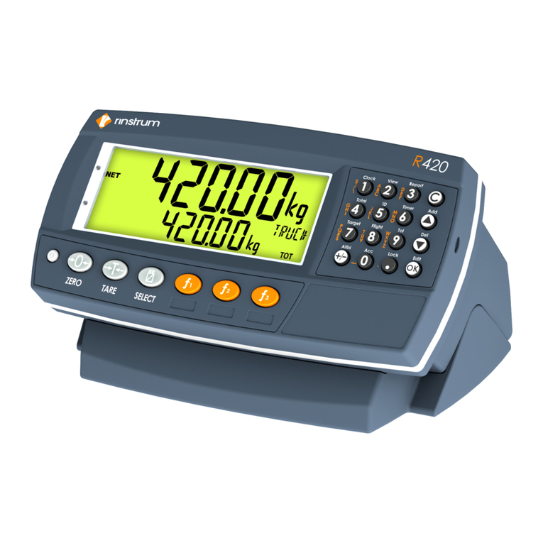
Rinstrum R320 User manual

Reference Manual V1.00 SoftwareVersions3.xx
003R-677-210 Page1
Table of Contents
1. INTRODUCTION................................................................................................................... 5
1.1. Overview.................................................................................................................... 5
1.2. Approvals................................................................................................................... 5
1.2.1. Trade versions ........................................................................................... 6
1.3. The ManualsSet........................................................................................................ 6
1.4. ThisReference Manual.............................................................................................. 6
1.5. Document Conventions.............................................................................................. 6
2. SPECIFICATIONS................................................................................................................. 7
3. INSTALLATION.................................................................................................................... 8
3.1. Introduction................................................................................................................ 8
3.2. GeneralWarnings...................................................................................................... 8
3.3. ElectricalSafety......................................................................................................... 8
3.4. Cleaning..................................................................................................................... 8
3.5. PanelMount Template............................................................................................... 8
3.6. CableConnections..................................................................................................... 9
3.7. DC Power (DC PWR+ , DC PWR–)......................................................................... 9
3.8. Load Cell Connection................................................................................................. 9
3.8.1. Load Cell Signalsand ScaleBuild.............................................................. 9
3.8.2. 4-WireConnection ................................................................................... 10
3.8.3. 6-WireConnection ................................................................................... 10
3.9. AuxiliaryConnections............................................................................................... 11
3.9.1. RS-232 Serial........................................................................................... 11
3.9.2. RemoteInput........................................................................................... 14
3.9.3. Outputs.................................................................................................... 15
3.10. opto-LINK (Optional)................................................................................................ 16
3.11. ConnectingShields.................................................................................................. 17
3.11.1. CableShieldConnection and Earthing..................................................... 17
3.12. RegulatorySealingRequirements............................................................................ 17
4. DATAENTRY...................................................................................................................... 18
4.1. EditingAnnunciators................................................................................................ 18
4.2. NumericEntry.......................................................................................................... 19
4.3. Selections and Options ............................................................................................ 19
5. BASICOPERATION........................................................................................................... 20
5.1. Display..................................................................................................................... 20
5.2. Has akeybeen locked?........................................................................................... 21
5.3. EditingFunction ....................................................................................................... 21
5.4. Stability–What isa“StableError”?......................................................................... 21
5.5. POWER Key............................................................................................................ 21

Reference Manual V1.00 SoftwareVersions3.xx
Page2 003R-677-210
5.6. ZERO Key................................................................................................................ 22
5.7. TARE Key................................................................................................................ 22
5.8. GROSS/NETKey..................................................................................................... 23
5.9. PRINTKey............................................................................................................... 23
5.10. FUNCTIONKey....................................................................................................... 23
6. CONFIGURATION.............................................................................................................. 24
6.1. GeneralSetup Information....................................................................................... 24
6.2. BasicWeighingTerminology.................................................................................... 24
6.3. FilteringTechniques................................................................................................. 25
6.4. IndustrialvsOIMLand NTEP Modes ...................................................................... 25
6.5. Calibration Counter.................................................................................................. 25
6.6. Passcodes ............................................................................................................... 26
6.6.1. Full Setup Passcode ................................................................................ 26
6.6.2. SafeSetup Passcode............................................................................... 26
6.6.3. Setup Lock-Out........................................................................................ 26
7. CALIBRATION.................................................................................................................... 28
7.1. PerformingaDigitalCalibration withTest Weights................................................... 28
7.1.1. ZERO (ZeroCalibration Routine)............................................................. 29
7.1.2. SPAN (Span Calibration Routine)............................................................. 29
7.2. PerformingaCalibration withDirect mV/VEntry...................................................... 29
7.2.1. DIR.ZER(Direct ZeroCalibration Entry)................................................... 29
7.2.2. DIR.SPN (Direct Span Calibration Entry).................................................. 29
8. SETUP ................................................................................................................................ 30
8.1. AccessingSetup ...................................................................................................... 30
8.1.1. Access usingFull Setup........................................................................... 30
8.1.2. Access usingSafeSetup ......................................................................... 30
8.1.3. Setup DisplayPrompts............................................................................. 31
8.2. ExitingFull or SafeSetup......................................................................................... 31
8.3. Groups and Items.................................................................................................... 31
8.4. Setup Menus............................................................................................................ 32
8.4.1. BUILD(ScaleBuild)................................................................................. 32
8.4.2. OPTION(ScaleOptions).......................................................................... 33
8.4.3. CAL(ScaleCalibration)............................................................................ 34
8.4.4. SPEC (SpecialSettingsMenu)................................................................. 34
8.4.5. CLOC(Clock) –K35*............................................................................... 37
8.4.6. TEST(SpecialTest Functions)................................................................. 37
8.4.7. FACTRY (FactoryAdjustment Menu)....................................................... 38
8.4.8. –End –(LeavingSetup)........................................................................... 38
9. SERIALOUTPUTS(K344, K35*)........................................................................................ 39
9.1. SerialOutput Types ................................................................................................. 39


Reference Manual V1.00 SoftwareVersions3.xx
003R-677-210 Page3
9.2. NET- NetworkCommunications.............................................................................. 40
9.3. AutoWeight Format String....................................................................................... 40
9.4. Menu Setup - SERIAL(SerialCommunications Options)......................................... 41
10. STANDARD PRINTING –K344 (NO CLOCK/CALENDAR)................................................ 43
11. STANDARD PRINTING –K35*(WITHCLOCK/CALENDAR)............................................ 44
11.1. PrintingNumber ofPieces withCountingActive....................................................... 44
11.2. PrintingTotalWeight................................................................................................ 45
11.3. PrintingTotalWeight and Number ofPieces............................................................ 45
12. PROGRAMMABLE PRINTING –K35*................................................................................ 46
12.1. Howtoset custom print stringsusingView300....................................................... 46
12.2. Tokens..................................................................................................................... 46
12.3. UsingTokens Example............................................................................................ 46
12.4. Clear Custom Print Strings....................................................................................... 46
12.5. PrintingCustom Print Strings................................................................................... 47
12.6. Master SerialOutput................................................................................................ 47
12.7. AutoOutput Speed................................................................................................... 47
12.8. Print Interlock........................................................................................................... 47
13. SETPOINTS–K356............................................................................................................ 48
13.1. Setpoint Menu Setup - SET.PTS.............................................................................. 48
13.2. Setpoint Configuration.............................................................................................. 49
13.3. Setpoint Source ....................................................................................................... 49
13.4. Setpoint Target........................................................................................................ 49
13.5. Setpoint Type (OVER/UNDER) and Hysteresis........................................................ 50
14. SPECIALFUNCTIONS KEY –K35*................................................................................... 51
14.1. Introduction.............................................................................................................. 51
14.2. KeyFunctions .......................................................................................................... 51
14.2.1. NONE....................................................................................................... 51
14.2.2. TEST........................................................................................................ 51
14.2.3. COUNT.................................................................................................... 51
14.2.4. UNITS...................................................................................................... 51
14.2.5. HOLDand PEAK HOLD........................................................................... 52
14.2.6. SHOW.T.................................................................................................. 52
14.2.7. HI.RES..................................................................................................... 52
14.2.8. A.TARE.................................................................................................... 52
14.2.9. SET.PT(K356)......................................................................................... 53

Reference Manual V1.00 SoftwareVersions3.xx
Page4 003R-677-210
15. APPENDIX- TRADE SEALING DETAILS .......................................................................... 54
16. APPENDIX–ABS R320 DIMENSIONS.............................................................................. 55
17. APPENDIX–STAINLESS STEEL R323 DIMENSIONS ..................................................... 57
18. SETUP MENU QUICK REFERENCE.................................................................................. 59
19. ERRORMESSAGES .......................................................................................................... 61
19.1. WeighingErrors....................................................................................................... 61
19.2. Setup and Calibration Errors.................................................................................... 62
19.3. DiagnosticErrors..................................................................................................... 63
20. APPENDIX- RINWIRE PROTOCOL................................................................................... 64
21. GLOSSARY TERMS........................................................................................................... 67
21.1. List ofFigures .......................................................................................................... 67
21.2. List ofTables............................................................................................................ 68
22. INDEX ................................................................................................................................. 69

Reference Manual V1.00 SoftwareVersions3.xx
003R-677-210 Page5
1.Introduction
Thisinstrument isaprecision digitalindicator usingthe latest Sigma-Deltaanalogue todigital
conversion technologytoensurefast and accurateweight readings.
Figure1: Weight Indicator
The setup and calibration ofthe instrument aredigital, withanon-volatilesecuritystorefor all setup
parameters.
The instrument maybe operated from 4.8V, 7.2V, 9.6V, 12Vor 24Vbatteries or aDC power source
from 7Vto24V. Thereisasoft power on/off function that retains memoryofthe indicator’sstate.
Once an instrument isturned on it will automaticallystart up againifthe externalpower is
interrupted.
The instrument isfitted withopto-LINK communications as standard. Thisallowsatemporary
isolated communications linktobe established withaPC usingan opto-LINK cable, which enables
softwareupgrades and the use ofcomputerised setup and calibration viathe Viewer software.
Refer toopto-LINK (Optional) page16 for moreinformation.
1.1.Overview
Thisinstrument provides ZERO and TARE functionalityas well as moresetup options (eg.
serialand setpoints) and printingfunctionality.
It also supportsspecialfunctions (eg. peak-hold, averaging, counting, etc.), viathe user
definable <FUNCTION> key. It isequipped withan NVRAMstoretoensureday-to-day
operatingsettings(eg. ZERO, TARE,CLOCK, etc.), areretained when power isremoved.
Thisinstrument has twoisolated transistor outputswithstatus displayon the front panelas
well as the RS-232 communications port that can be used for printer drivingor connection to
aremotedisplayor PC. Thereisabuilt-inclockfor date-stampingprinted outputs.
1.2.Approvals
C-tickapproved and CE approved.

Reference Manual V1.00 SoftwareVersions3.xx
Page6 003R-677-210
1.2.1.Tradeversions
•NMI approval(4000 divisions at 0.8µV/division).
•NTEP approval(10000 divisions at 0.8µV/division).
1.3.TheManualsSet
Thismanualispart ofaset ofmanualscoveringthe setup and operation ofthe instrument.
The set includes the following:
•Reference Manual - Contains detailed information on calibration and setup. Thismanual
isintended for use byScaleTechnicians who areinstallingthe instrument.
•CommunicationsManual - Contains detailson the extended networkingcapabilities
(communications protocol).
1.4.ThisReference Manual
Thereareseveralindicatorsbased on the R320 withdifferingenclosureand mounting
arrangements. Thismanualcontains detailsofinformation common toall derivatives ofthe
R320 series ofindicators.
Note: Inthismanualanyreference tothe R320 includes the other indicatorsinthe series
except wherestated otherwise.
1.5.Document Conventions
The followingdocument conventions (typographical) areused throughout thisReference
Manual.
BoldText Boldtext denotes words and phrases tonote.
<Key> <Key> denotes aKeypad key.
Note: Inthe Specifications section the < symbolmeans less than
and the > symbolmeans greaterthan.
^ Thissymboldenotes one space
⊗Itemsmarked with ⊗indicatethat the settingisavailableonlyinFull
Setup and istrade critical. When trade criticalsettingsarechanged
the calibration counter will be incremented.

Reference Manual V1.00 SoftwareVersions3.xx
003R-677-210 Page7
2.Specifications
R320 (ABS Housing) R323 (Stainless Steel)
Resolution Up to60,000 divisions, minimumof 0.25µV/division
Zero Cancellation ± 2.0mV/V
SpanAdjustment 0.1mV/V to3.0mV/V full scale
Excitation 5V for up to4x350 or 8x700 ohmload cells (4-wire or 6-wire plus shield)
Maxtotalload cell resistance: 3,500 (4x350 Nontrade 8x350 )
A/DType 24bit SigmaDeltawith8,388,608 internalcounts
20 updates/second
Operating Environment Temperature: –10°to+50°Cambient (14°to122°F)
Humidity: <90% non-condensing
IP65 when panelmounted
Display LEDBacklit LCD withsix20mm (0.8")high digits withunits and annunciators
Setup and Calibration Full digitalwithvisualprompting inplainmessages
Digital Filter Sliding windowaverage from0.1to4.0s
Zero Range Selectablefrom± 2% to± 100% Full Scale
Standard PowerInput 7to24VDC, 4.8, 9.6,12 and 24V batteries (2.5VA max)
ON/OFF keywithmemoryfeature
Variants
AC ACPlug pack: 110/240VAC50/60Hzin12VDC
1.5A out ACPower supply: 110/240VAC50/60Hz
in12VDC 1.2A out
Battery 12V batterypack (rechargeableNiMH) 12V batterypack (rechargeableNiMH)
4xAA batteries -
Case Materials ABS Housing Stainless SteelFlushMount
Packing Weights Basic Indicator: 0.34kg(12oz) Basic Indicator: 0.49kg(17oz)
Optical Data Communications Magneticallycoupled infra-red communications
Conversion cables availablefor RS232 or USB
K342 K344 K354 K356
Serial Outputs - RS232 automatic transmit, network or printer outputs.
Transmission rate: 2400, 4800, 9600 or 19200 baud
Functions ManualHoldUnit switching, counting, manualhold, peak hold,,
totalising, high resolution, autotare, displaytest
AssignableFunction Keys Fixed toHold 1
BatteryBackedClock Calendar - Batterylife10 years minimum
Input/Outputs - 2Outputs -
isolated transistor driveoutputs
(300mA totalat 50VDC)
- 1 Input
Set points - 2
Approvals 4,000 d@0.8uV/dNMI (S-420),OIMLR76
10,000d III/III LNTEP 08-072 A1
FCC, CE, C-tick,

Reference Manual V1.00 SoftwareVersions3.xx
Page8 003R-677-210
3. Installation
3.1.Introduction
The followingsteps arerequired toset up the indicator.
•Inspect indicator toensuregood condition.
•Use connection diagramstowireup load cell, power and auxiliarycables as required.
•Use the panelmount templateprovided for holelocations.
•Connect Power toindicator and press <POWER> keytoturnthe instrument on.
•Refer tothe Setup section page30 for information on configuringand calibratingthe
instrument.
•Toturninstrument off press and hold <POWER> keyfor three seconds (until display
blanks).
3.2.General Warnings
•Indicator not tobe subject toshock, excessivevibration or extremes oftemperature
(beforeor after installation).
•Inputsareprotected against electricalinterference, but excessivelevelsofelectro-
magneticradiation and RFI mayaffect the accuracyand stability.
•The instrument shouldbe installed awayfrom anysources ofexcessiveelectricalnoise.
•The load cell cableisparticularlysensitivetoelectricalnoise and shouldbe located well
awayfrom anypower or switchingcircuits.
•For full EMCor for RFI immunity, termination ofcableshields and correct earthingofthe
instrument isessential.
•Indicator and load cell cablearesensitivetoexcessiveelectricalnoise. Install well away
from anypower or switchingcircuits.
3.3.Electrical Safety
•For your protection all mains electricalhardwaremust be rated for environmental
conditions ofuse.
•Pluggableequipment must be installed near an easilyaccessiblepower socket outlet.
•Toavoidthe possibilityofelectricshockor damagetothe instrument, alwaysswitch off
or isolatethe instrument from the power supplybeforemaintenance iscarried out.
3.4.Cleaning
•Tomaintainthe instrument, never use harsh abrasivecleanersor solvents. Wipe the
instrument withasoft cloth slightly dampened withwarm soapywater.
3.5.Panel Mount Template
Use the panelmount templatefor drill holelocations. The templateindicates positions for the
two4mm mountingscrewsthroughthe panel. Also displayed on the templateisthe position
ofthe rectangular holethat shouldbe cut toallowfor the connection ofcables. The template
supplied withthe indicator allowsfor front or rear machiningofthe panel.

Reference Manual V1.00 SoftwareVersions3.xx
003R-677-210 Page9
3.6.CableConnections
All cableconnections aremade tothe rear ofthe instrument usingscrewless terminals.
Wires must be stripped ofinsulation byat least 10mm. Toinstall, depress the orangelever
beside the terminalrequired and push wireintothe hole. Release the lever and pull gentlyon
the wiretoensureit issecurelytrapped inthe terminal. It isnot necessarytotinthe ends of
the wirewithsolder or toadd crimpferrules tothe wires, however, these techniques arealso
compatiblewiththe terminalsand mayultimatelymakefor aneater job.
Figure2: CableConnections
3.7.DC Power(DC PWR+ , DC PWR–)
The DC supplyneed not be regulated, provided that it isfree ofexcessiveelectricalnoise and
sudden transients. The instrument can be operated from ahighqualityplug-packas longas
thereissufficient capacitytodrivebothit and the load cells.
Ifan optionalbatterypackisfitted, then the supplied chargingsystem must be used.
3.8.LoadCell Connection
3.8.1.LoadCell Signalsand ScaleBuild
Verylowoutput scalebases maybe used but mayresult insomeinstabilityinthe weight
readingswhen used at higher resolutions. Generallyspeaking, the higher the load cell output,
or the lower the number ofdivisions, the greater the displaystabilityand accuracy.
The instrument can displaythe millivolt-per-volt readingthat can be used tocheckscalebase
signaloutput levels. For moreinformation, refer toTEST(SpecialTest Functions) page37.
The instrument maybe connected for either 4-wireor 6–wireoperation. Tocorrespond withthe
actualcablinginstallation the instrument must be configured insetup tothe correct setting. For
moreinformation, refer to CABLE
(4-Wireor6-Wire) ⊗page32.

Reference Manual V1.00 SoftwareVersions3.xx
Page10 003R-677-210
3.8.2.4-WireConnection
The minimum connectivityrequirementsarethe connection offour wires (ie. Excitation + and
–alongwithSignal+ and –). Internallythe instrument has aprecision analogue switch that
connectsthe Sense + and –lines directlytothe Excitation + and –lines when 4-wiremode is
selected.
A4-wireconnection isonlysuitablefor short cableruns. Wherelongcablelengths are
needed, a6-wireextension isrequired tomaintainaccuracy.
The BUILD:CABLEoption must be set to 4 toallowfor 4-wireconnection. Refer to CABLE
(4-Wireor6-Wire) ⊗page32.
Figure3: 4-WireConnections
3.8.3.6-WireConnection
The excitation and signallines areconnected the sameas for a4-wireinstallation. The extra
twowires (Sense + and –) shouldbe connected tothe Excitation + and –lines as close as
possibletothe load cell itself. Typicallythese connections aremade inaload cell termination
box.
The BUILD:CABLEoption must be set to 6 (the default) toallowfor 6-wireconnection. Refer to
CABLE
(4-Wireor6-Wire) ⊗page32.
Figure4: 6-WireConnections

Reference Manual V1.00 SoftwareVersions3.xx
003R-677-210 Page11
3.9.AuxiliaryConnections
Thissection provides diagramstoillustratethe terminalconnections.
3.9.1.RS-232 Serial
Network: OneInstrument toPC (RXD, TXD, GND)
Figure5: RS-232 –OneInstrument toPC using COM Port (DB9)
Figure6: RS-232 –OneInstrument toPC using COM Port (DB25)

Reference Manual V1.00 SoftwareVersions3.xx
Page12 003R-677-210
Ring Networks: MultipleInstrumentstoPC (RXD, TXD, GND)
Instrumentscan be configured inaRingNetwork.
The Short RingNetworklayout can be used insituations up toatotalcablerun lengthof
about 150 m (500 ft) at 9600 baud inaclean EMCenvironment. Ifthereare
communications errors, or for longer cableruns, lower the baud rateto4800 or 2400,
and/or use the LongRingNetworkinFigure8below, which uses aseparatereturnpath
from the ‘Last Instrument’tothe PC.
For DB25 connections at the PC connector, refer toFigure6above.
When operatinginaRingNetwork, the Instrumentsmust have:
•same serialport options, i.e., baud, parity, databits, stop bits;
•unique addresses.
Short Ring Network: MultipleInstrumentstoPC (RXD, TXD, GND)
Figure7: RS-232 Short CableRuns: Ring Networkusing COM Port (DB9)

Reference Manual V1.00 SoftwareVersions3.xx
003R-677-210 Page13
Long Ring Network: MultipleInstrumentstoPC (RXD, TXD, GND)
The LongRingNetworklayout can be used insituations whereeach legofthe cablerun
can be up toabout 150 m (500 ft) at 9600 baud. Iftherearecommunications errors,
lower the baud rateto4800 or 2400.
Figure8: RS-232 Long CableRuns: Ring Networkusing COM Port (DB9)

Reference Manual V1.00 SoftwareVersions3.xx
Page14 003R-677-210
PrinterConnections(RXD/TXD, GND and DTR)
Figure9: RS-232 –Instrument toPrinter(DB25)
RemoteDisplay(TXD, GND)
The remotedisplaydocumentation shouldbe referred tofor connection details. Connect
TXDtoRXDand GND toGND on the remotedisplay.
3.9.2.RemoteInput
The indicator requires avoltagefree contact between TXDand RXDtoenablethe
remoteinput (ie. SPEC:REM.FN). The SERIAL:TYPE option must be set toAUTO,
PRINTor AUTO.PR. When usingSERIAL:TYPE ofPRINTor AUTO.PR, the
SPEC:REM.CHR must be set toan appropriatecharacter that will not affect the printer.
Thischaracter will be sent repeatedlywhen the transmitter isidle, regardless ofthe state
ofthe DTRline. Note: The remoteinput will not function when insetup or when using
the opto-LINK.
Note: AutoOutput Speed must be set to10Hz.
WARNING
Theremoteinput isavoltagefree contact (eg.
button, mechanical relay). Connection of any
activecircuitrymaydamagetheinstrument.
Figure10: RemoteInput

Reference Manual V1.00 SoftwareVersions3.xx
003R-677-210 Page15
3.9.3.Outputs
The output driversfor the instrument areisolated open emitter transistor drives that are
capableofdrivingup toatotalof300mA. Thisconfiguration allowsfor the direct connection
ofthe instrument outputstomost types ofPLC.
The voltageapplied tothe COMterminalappearson the output lines (ie. OUT1and OUT2)
when the outputsareactive(eg. toconnect toaPLCconnect +24Vtothe common terminal).
The outputscan then be connected directlytoPLCinputsso when activated areactivethe
PLCwill see a22Vsignal(approx. - the exact switch loss will depend on loadingofthe
output).
Todriveexternalloads (eg. relays), connect the relaycoil positivesupplytothe output
common and the output line directlytoone side ofthe relaycoil. Connect the other end of
the relaycoil tothe negativesupply. It isrecommended that fly-backdiodes or transient
suppressorsbe fitted across relaycoilstolimit switchingnoise.
Figure11: Instrument OutputstoDriveRelay
Figure12: Instrument OutputstoDrivePLC

Reference Manual V1.00 SoftwareVersions3.xx
Page16 003R-677-210
3.10.opto-LINK (Optional)
Atemporaryinfrared communications linkcan be established between the instrument and a
PC usingan optionalopto-LINK cable. The optionalopto-LINK cablecan be used totransfer
setup and calibration information from aPC (eg. tobe stored for later use and/or transferred
toother instruments). It can also be used todownload softwareupgrades tothe instrument
from aPC.
The PC end ofthe opto-LINK cableisastandardfemaleDB9connector, or USB connector.
The instrument end ofthe cableconsistsofan infrared transceiver, which attaches tothe left
side ofthe instrument display. Tofacilitateaquickand simpleconnection, the infrared
transceiver issecured inplace byapermanent magnet located withinthe head ofthe opto-
LINK.
Refer toopto-LINK Activation page23 for moreinformation.
WARNING
Theopto-LINK headcontainsastrong magnet and careshouldbetakenwithits
proximitytoelectronicmedia(eg. credit cards, floppydisks, etc.) and/orother
electronicinstrumentation.
Figure13: opto-LINK Attachment

Reference Manual V1.00 SoftwareVersions3.xx
003R-677-210 Page17
3.11.Connecting Shields
Toobtainfull EMCor for RFI immunity, cableshields MUSTbe connected tothe earthlugon
the rear ofthe instrument.
Figure14 illustrates an exampleofpossibleconnections. Also shownarethe connecting
cables restrained usingcableties fastened around the cablestrainreliefanchors.
Figure14: CableShieldConnection
3.11.1.CableShieldConnection and Earthing
•Careshouldbe taken when connectingshields tomaximise EMCor RFI immunityand
minimise earthloops and cross-talk(interference) between instruments.
•For full EMCor for RFI immunity, termination ofthe cableshields at the earthlugisvery
important. The earthlugofthe instrument must be separatelyconnected toground
potentialviaareliablelink.
•The instrument shouldonlybe connected toearthviaasinglereliablelinktoavoidearth
loops.
•Whereeach instrument isseparatelyearthed, interconnectingcableshields shouldbe
connected at one end only. Thisalso applies tocommunications cableshields inRing
Networks, refer toShort RingNetworkand LongRingNetworkconnections under ‘RS-
232 Serial’ pages 12 and 13.
•Caution: Someload cellsconnect the cableshielddirectlytothe load cell (and therefore
the scalebase). Connection ofthe load cell cableshieldinthissituation maybe site
specific.
3.12.RegulatorySealing Requirements
Tocomplywithregulatorysealingrequirementsfor each instrument, (ie. toensureinstrumentsare
not accidentallyor deliberatelytampered with), it isimportant that proper sealingprocedures be
adhered to. Refer toAppendix- Trade Sealingpage54 for moreinformation.

Reference Manual V1.00 SoftwareVersions3.xx
Page18 003R-677-210
4. Data Entry
Throughout the setup and normalweighingmode, different dataentrymethods areused. Each
method isdescribed below.
When usingthe keypad for normaloperation, press the keyon keypad toinitiatethe feature.
4.1.Editing Annunciators
When inSetup the instrument displaysEditingAnnunciators. Figure15 identifies each ofthe
editingannunciators. When inSetup, press the correspondingkeypad keybelowthe
annunciator.
Figure15: Editing Annunciators
Editing
Annunciator KeyName Description
GRP ZERO Steps throughthe list ofGroups.
ITM TARE Steps throughthe list ofItems.
Press thiskeytoaccept changes and returntothe
menus.
(Also refer tothe OK description below.)
SEL GROSS/NET Moves the editingcursor insomeeditingmodes.
EDT PRINTSteps throughthe availableoptions when editinga
particular item.
OK OK
(FUNCTION) Press thiskeytoaccept changes and returntothe
menus.
(Also refer tothe ITM description above.)

Reference Manual V1.00 SoftwareVersions3.xx
003R-677-210 Page19
4.2.NumericEntry
Anumericentryboxallowsthe input ofanumber. When enteringanumber, the displaywill
showdigitswiththe currentlyselected digit flashing. The <SEL> keyispressed toselect a
digit tochange. When the digit isselected the <EDT> keyispressed tochangethe digit
from 0through 9. The left most digit can also be changed toadash (-) toenter anegative
number. The <OK> keyispressed toaccept the number that has been entered and returnto
the menu item.
Upper and lower limitsareplaced on someentries and an entryoutside thisrangewill cause
the instrument todisplaydashes (ie. - - - - - -).
Example: When inSetup followthe steps belowtoset Build, MaxCapacity.
Press <GRP> repeatedlytodisplaythe BUILD group.
Press <ITM> repeatedlytodisplaythe CAP item.
Press <SEL> toselect CAP and displaythe current setting(eg. 0000.00kg).
The currentlychosen digit will be flashing. Press <SEL> toadvance tothe next digit.
When the digit toedit isflashing, press <EDT> repeatedlytocyclefrom 0through 9.
When the newdigit tobe set isflashingeither press <SEL> tomovetothe next digit toedit
and repeat the previous step; or press <OK> or <ITM> toaccept all ofthe displayed
digits(includingthe flashingdigit) and re-displaythe menu item name.
4.3.Selectionsand Options
Aselection entryrequires the choice ofasingleoption from alist. When aGroup and Item
havebeen chosen, the <SEL> keyisused todisplaythe current settingfor that item. The
<EDT> keycan be used tocyclethroughthe options for that item. When the desired option
isdisplayed the <OK> keycan be pressed toaccept the displayed option and re-displaythe
item name.
Example: When inSetup followthe steps belowtoset Options, Filter.
Press <GRP> repeatedlytodisplaythe OPTION group.
Press <ITM> repeatedlytodisplaythe FILTER item.
Press <SEL> toselect FILTER and displaythe current setting.
Press <EDT> tocyclethroughthe options for that item.
Press <OK> or <ITM> toaccept the displayed option and re-displaythe menu item name.

Reference Manual V1.00 SoftwareVersions3.xx
Page20 003R-677-210
5. Basic Operation
Figure16: Displayand ControlsIllustration
5.1.Display
Weight
Display The Weight Displayindicates the weight readings, setup information, errorsand
warnings.
Units
Display
The UnitsDisplayshowsthe unitsofthe weight readingas: grams(g), kilograms(kg),
pounds (lb), tonnes (t) or none.
Ifthe instrument isset up for countingthe unitsdisplaywill showpieces (p).
Annunciators
ZERO Visiblewhen the gross readingiswithin ±¼ ofadivision
oftrue zero.
NET Visiblewhen the displayed readingrepresentsNET
weight.
MOTION Visiblewhen the displayed readingisnot stable.
OVER Visiblewhen either ofthe setpointsisset as type OVER,
and the weight isabovethe target weight.
UNDER Visiblewhen either ofthe setpointsisset as type
UNDER, and the weight isbelowthe target weight.
1 OUT1 Visiblewhen Output 1isturned ON.
2 OUT2 Visiblewhen Output 2isturned ON.
ZERO BAND Visiblewhen the displayed weight iswithinthe zero
'dead' band setting. (The zeroband symbolshowsnear
the top right corner ofthe display.)
HOLD Visiblewhen the displayed readingisheld.
LOW
BATTERY
Visiblewhen batteryvoltageistoo lowand batteries
need replacingor recharging. (The lowbatterysymbol
showsinthe top right corner ofthe display.)
When inSetup the editingannunciatorsareshowntoidentifythe function ofthe front
panelkeys(ie. GRP, ITM, SEL, EDT and OK). For moreinformation refer toEditing
Annunciatorspage18.
This manual suits for next models
1
Table of contents
Other Rinstrum Accessories manuals

Rinstrum
Rinstrum 400 Series User manual

Rinstrum
Rinstrum 400 Series User manual

Rinstrum
Rinstrum K404 User manual

Rinstrum
Rinstrum K404 User manual

Rinstrum
Rinstrum X300 IP69K376 User manual

Rinstrum
Rinstrum 1203 User manual

Rinstrum
Rinstrum K410 User manual

Rinstrum
Rinstrum 5100 Use and care manual

Rinstrum
Rinstrum R323 Use and care manual