RioOutdoors 4F-DC User manual

1 | Page
Installation Instructions
4F-DC
4x4 Floating Double Cubic Pergola Kit
Pergola Kits
WARNING: If the information in these instructions is not followed exactly, weakening or failure of the erected
structure may result causing property damage, personal injury, or loss of life.
All brackets designed and sold by RioOutdoors.com are to be used for building pergolas only and are not to be used for
other structure construction purposes.
•
Thoughtfully engineered
Brackets eliminate all wood-
joinery skills requirements.
•Skills required: drill holes
in concrete and hammer
in anchors, drilling pilot
holes and driving lag
screws into lumber.
•Easy lift and place U-
channels eliminate need
for lifting equipment.
Super-easy assembly
work.
•Self-aligning design
squares up structure
automatically.
•Estimated Assembly
Time is less than 2 hours.
Figure 1: Items included in the kit, (
).
Items not included in this kit: wood, tools, some hardware.

2 | Page
Table of Contents
1.1 SAFETY AND WARNING INFORMATION ........................3
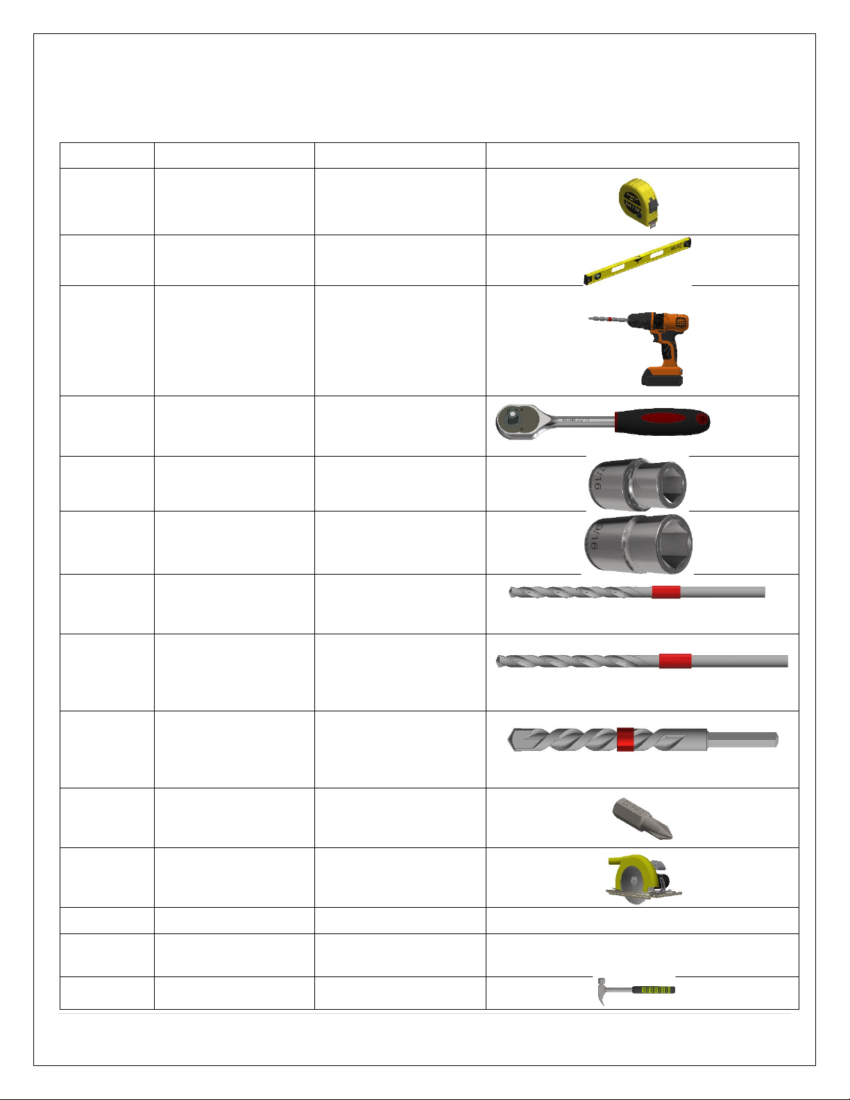
1.2 TOOLS REQUIRED...................................................4
1.3 CONTENTS OF KIT #4F-DC ......................................5
1.4 LIST OF MATERIALS THAT YOU WILL SUPPLY ..................5
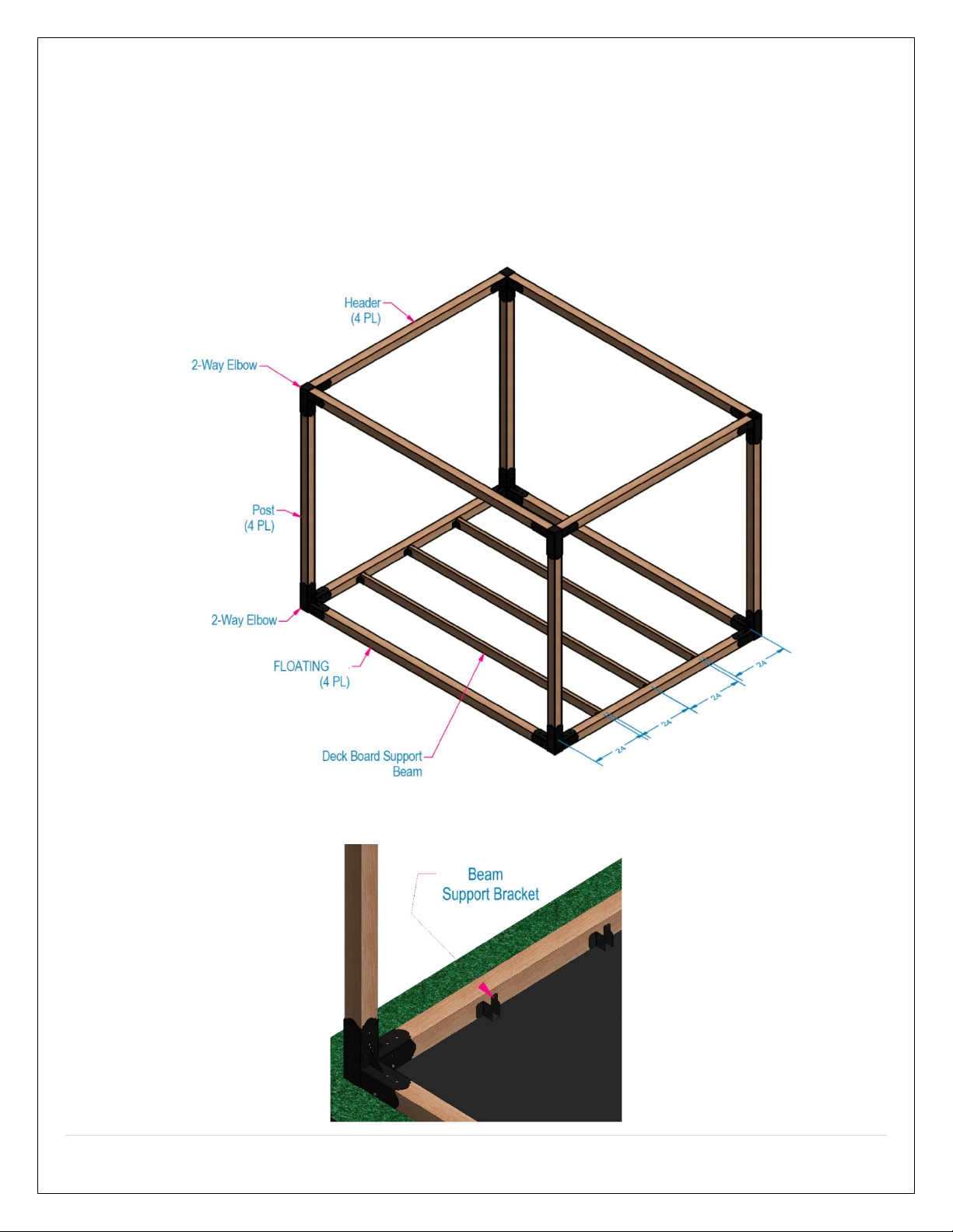
1.5 FLOATING SYSTEM...............................................6
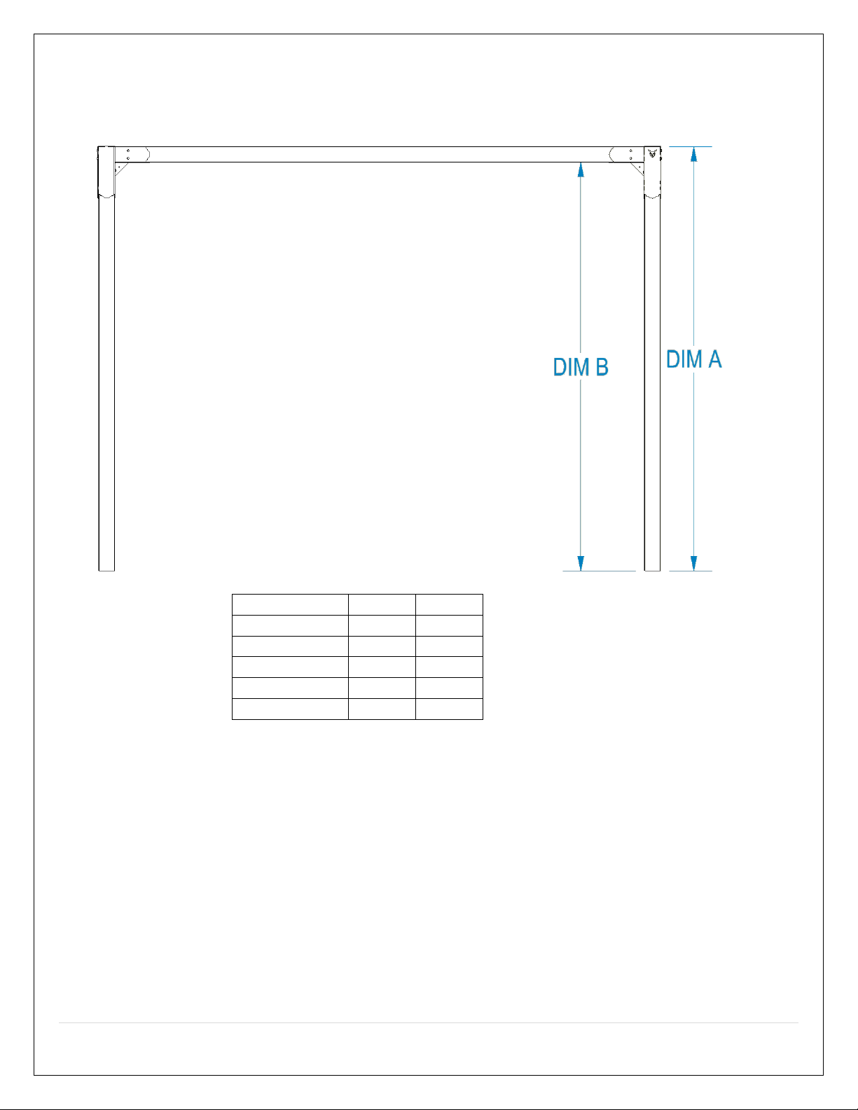
1.6 OVERALL PERGOLA SIZE ...........................................8
1.7 SIDE ELEVATION DIAGRAM .......................................9
1.8 ASSEMBLING FLOOR CORNER 2-WAY ELBOW BRACKETS 10
1.9 ASSEMBLING THE FLOOR 2-WAY EXTENSION BRACKET . 12
1.10 POSTS INSTALLATION ........................................... 17
1.11 POST-TOP BRACKETS INSTALLATION ........................ 18
1.12 POST TOP 2-WAY EXTENSION BRACKET INSTALLATION 21
1.13 4X4HEADERS INSTALLATION ................................. 23
2.1 CONDITIONS ...................................................... 26
2.2 EXCLUSIONS....................................................... 26
2.3 LIMITATIONS OF LIABILITY ..................................... 27
2.4 HOW TO OBTAIN WARRANTY SERVICE ..................... 27
Proper pilot hole diameter and hole depth for various lag screws and wood types
Lag Screw Type
Wood Type
Pilot hole drill diameter and hole depth
¼” X 1-1/4” Lag Screw
McMasterCarr.com SKU 92351A546
Soft Wood 3/32” drill bit diam., 1-1/4” depth
Hard Wood 3/16” drill bit diam., 1-1/4” depth
3/8” X 3” Lag Screw
McMasterCarr.com SKU 92351A636
Soft Wood 11/64” drill bit diam., 3” depth
Hard Wood ¼” drill bit diam., 3” depth
A properly sized pilot hole must be drilled before you attempt to drive lag screws into any pergola lumber member.
See Table, below. Driving lag screws into lumber, without first drilling a pilot hole, can prevent the lag screw from
driving fully into the wood or can lead to crack formation while driving the lag screw in, or later, as the wood dries
naturally. This can result in a weakened pergola structure.

3 | Page
GENERAL INFORMATION
1.1 SAFETY AND WARNING INFORMATION
1.1.1 Building Permit & Inspection Requirements
We recommend that you consult with your local building permit office and obtain advice and any required building permits and
inspection approvals from the local building inspection department or the local jurisdiction having authority over building codes.
1.1.2 Other Cautions
CAUTION: Adhere to all safety requirements. Wear safety glasses/goggles when working. Wear safety gloves
when handling brackets, hardware, and lumber. Wear hearing protection when using a circular saw, miter
saw, table saw, or hammer drill.
INSTALLER: Leave this manual with the consumer. CONSUMER: Retain this manual for future reference.

4 | Page
1.2 TOOLS REQUIRED
Listed below, are common tools required for pergola projects. These tools are not included in this kit. Your pergola project may
not require all tools. Select and acquire the tools for your project from the “Required for” column in this table.
Description
Tool Purpose
Required for
Reference Image
Tape
Measure
Measure and verify
lengths. All pergola types
Framing
Level Verify Level/Plumb All pergola types
Hammer
Drill
Drill holes in concrete
pads or concrete
footing for securing
floor anchor brackets.
Drill pilot holes for lag
screws.
All pergola types
Ratchet
Socket
Driver
Drive lag screws into
Pergola lumber
members.
All pergola types
7/16” Hex
Socket
Drive ¼” X 1-1/4” Hex
Hd. lag screws. All pergola types
9/16” Hex
Socket
Drive 3/8” X 3” Hex Hd.
lag screws.
Raftered pergola (single,
dual, quad headers)
3/32” Drill
Bit
Drill pilot holes for ¼”
lag screws in soft wood. All pergola types
11/64” Drill
Bit
Drill pilot holes for 3/8”
lag screws in soft wood.
Raftered pergola (single,
dual, quad headers)
½” X 4”
Masonry
Drill Bit
Drill ½” X 2” deep holes
in concrete pads or
concrete footings.
Surface Mount styled
pergola
#2 Phillips
Screwdriver
Bit
Attaching pergola
rafter ties to rafters
and headers.
Raftered pergola (single,
dual, quad headers)
Circular
Saw/Miter
Saw
Cut headers to length;
cut rafters to length. All pergola types
Jig Saw
Cut rafter tail designs.
Raftered pergolas
Image not available.
Crescent
Wrench
Tighten down nut on
concrete anchors. Surface Mount Pergolas Image not available.
Hammer Various. All pergola types.

5 | Page
1.3 CONTENTS OF KIT # 4F-DC
The contents of this kit are shown in the table, below. Before you begin your project, take an inventory of all items that you
received from us. If any items are missing, contact us directly via email at info@RioOutdoors.com. Include your name and
shipping address and your order number, if available. We will respond within 24 hours with a resolution to your problem.
Item SKU #, Description
Item Qty
Item Image
4x4 Post-Top/Floor 2-way Elbow Bracket
SKU# 4C2L 8
4x4 Post-Top/Floor 2-Way Straight Extension
SKU #4SE 4
¼ x 1-1/4” Lag Screw 120
1.4 LIST OF MATERIALS THAT YOU WILL SUPPLY
This is the list of required materials which are not included in this kit. You will acquire these items locally for your project. Use
this table to help you calculate your total project budget.
Item Description Item Qty
Item Cost
($)
Total Item
Cost ($)
Item Image
4x4 Post Lumber (You determine length) 6
NA
4x4 Header Lumber (You determine length)
6
NA
4x4 Floor Floating Lumber (You determine length)
6
NA
Tape, for marking drill bit depth
2”
NA
Grand Total Cost ($)
NA

6 | Page
1.5 FLOATING SYSTEM
1.5.1 What is a floating system?
Floating means that the vertical posts for the pergola are secured to 4x4s that are laid on the ground and floating; employing 2-
way elbow brackets to secure the posts to the floating floor 4x4s. You may choose to create a wooden deck within the pergola
walls. To do so, you must add support beams every 24” to support the deck boards. You may toenail the beams in place or
choose an easier and more precise mounting method using our Beam Support Brackets (SKU# 24BS, available at
RioOutdoors.com).

7 | Page
1.5.2 Floor Leveling and Preparation.
Plan to assemble a floating pergola where you can excavate and create a level platform, at least, the overall outer dimensions of
the pergola. If soil type is sandy, soft, or wet, you must consider adding concrete blocks or pier blocks under corners of pergola to
prevent sinking into soil.
1. Excavate enough dirt to create a flat and level platform.
2. Spray Roundup weed killer herbicide on the excavated area to prevent weed growth inside your pergola area.
3. Lay thick weed control fabric over the entire pegola platform. Overlap the fabric at least 6 inches where they join. Use U-
shaped lanscaping fabric nails to anchor the fabric to the ground.
Alternatively, you can excavate deeper, about 3 inches, lay the weed control fabric at the bottom and fill the excavated
area on top of the fabric with gravel up to your desired height.
4. Layout the four floating floor 4x4s in the intended shape and orientation on top of the leveled area.

8 | Page
1.6 OVERALL PERGOLA SIZE
We have designed the corner elbow brackets to provide automatic squaring and alignment of the floating 4x4s. By following
the instructions properly and securing the 4x4s to the elbow brackets as instructed, you will achieve a perfectly squared
floating deck base for your pergola. All you have to do is determine the size you desire for the length and width of your
pergola.
We recommend a maximum header length of 12 feet for 4x4 headers. Before you start assembly, study the table, below, and
determine the lengths of the bottom 4x4 members you will need.
DIM A
DIM B
DIM C
DIM D
DIM E
DIM F
OVERALL
WIDTH
OVERALL
LENGTH
96
99 3/4
96
99 3/4
96
99 3/4
103 1/2
203 1/4
108
111 3/4
108
111 3/4
108
111 3/4
115 1/2
227 1/4
120
123 3/4
120
123 3/4
120
123 3/4
127 1/2
251 1/4
132
135 3/4
132
135 3/4
132
135 3/4
139 1/2
275 1/4
144
147 3/4
144
147 3/4
144
147 3/4
151 1/2
299 1/4

9 | Page
1.7 SIDE ELEVATION DIAGRAM
Based on the height of the post used, the diagram below provides the side elevation profile for this pergola system.
POST HEIGHT
DIM A
DIM B
96
96
92.5
108
108
104.5
120
120
116.5
132
132
128.5
144
144
140.5
Dim A, above, is the height of the post used. Dim B is the inner ceiling height of the pergola. Dim B is measured to the bottom
surface of the header member.

10 | Page
1.8 ASSEMBLING FLOOR CORNER 2-WAY ELBOW BRACKETS
1. Starting in one corner, slide one 2-way elbow over two adjacent 4x4s so the U-channels in the 2-way elbow bracket are
over the 4x4s.
2. Place two shims under each 4x4 near the 2-way elbow.
3. Push 2-way elbow bracket downward until the horizontal part of the U-channels touch the 4x4 top surfaces.
4. Slide 4x4s all the way in towards the center square tube in the 2-way elbow bracket.

11 | Page
5. Wrap a piece of electrical tape around the drill bit, spaced 1-1/4” from the drill bit tip. This will act as a hole depth
indicator when you drill each pilot hole. Pilot holes should be drilled at least 1-1/4” deep. A little bit deeper is acceptable
but do not drill less than the required 1-1/4” depth.
6. Drill 3/32 X 1-1/4” pilot holes through the lower holes in the U-channel’s sides, on both visible and not visible sides. Only
use the lower holes to anchor the floor 4x4s to the U-channels.
7. Drive one ¼” X 1-1/4” lag screw through the pilot holes you drilled.
8. Repeate steps 6 and 7 for the other side of both U-channels.

12 | Page
1.9 ASSEMBLING THE FLOOR 2-WAY EXTENSION BRACKET
1. Move to the opposite end of the floating 4x4 which runs along the length of the pergola.
2. Slide one 2-Way Extension Bracket over the end of the length-side floating member. Butt the square vertical tube against
the end of the 4x4.
3. Slide one wood shim under the 4x4 from each side to prop the 4x4 upward.
4. Hold the 2-Way Extension bracket tightly against the 4x4 end and top face.

13 | Page
5. Drill a 3/32” X 1-1/4” pilot hole through the bottom 5/16” hole on both sides of the U-Channel which is over the 4x4. Drill
through only the bottom holes.
6. Using a Ratchet driver and a 7/16” socket, drive a ¼” x 1-1/4” Lag Screw through the pilot holes you drilled. Tighten the
lag screws.
7.

14 | Page
8. Slide a floating 4x4 on the other end of the 2-Way Extension bracket.
9. Place two shims under the 4x4 to push it upward.
10. Drill a 3/32” X 1-1/4” pilot hole through the bottom 5/16” hole on both sides of the U-Channel which is over the new 4x4.
Drill through only the bottom holes.

15 | Page
12. Using a Ratchet driver and a 7/16” socket, drive a ¼” x 1-1/4” Lag Screw through the pilot holes you drilled. Tighten the
lag screws.

16 | Page
13. Repeat sections 1.9 and 1.10 as you work around the perimeter to create the floor floating structure.
14. Remove all shims from under the 4x4s.
15. Tap top of 4x4s with a hammer to settle the 4x4s into the ground fabric.
16. Using a 4 foot framing Level, check top surfaces of all 4x4s to see if they are level. Use shims as you see necessary to level
all 4x4s that are sitting on the ground.

17 | Page
1.10 POSTS INSTALLATION
1. Slide a 4x4 post inside the open vertical tube in all four corners’ 2-way elbow bracket.
2. Identify the 5/16” holes in the inner faces of the 2-way elbow’s vertical tube. Drill 3/32” X 1-1/4” pilot holes in the center of
all four 5/16” holes.
3. Drive one 1/4x1-1/4” lag screw through each pilot hole you drilled and tighten down using a ratchet and 7/16” socket.
Repeat steps 1 to 3 at all corners. Check top of floor 4x4 for level on more time and adjust as necessary to maintain level.

18 | Page
1.11 POST-TOP BRACKETS INSTALLATION
1. Slide the 2-way elbow bracket’s tube over the 4x4 post top after aligning the header receiver u-channels in the proper
direction. Let gravity work and pull the bracket all the way down on top of the post.
2. Identify the four 5/16” holes which are on the sides of the gussets in the bracket.

19 | Page
3. Wrap a piece of electrical tape around the drill bit, spaced 1-1/4” from the drill bit tip. This will act as a hole depth indicator
when you drill each pilot hole. Pilot holes should be drilled at least 1-1/4” deep. A little bit deeper is acceptable but do not
drill less than the required 1-1/4” depth.
4. Drill 3/32” X 1-1/4” deep pilot holes at the center of four 5/16” Holes. Locate pilot holes at the center of each 5/16”
hole.

20 | Page
5. Drive one ¼ x 1-1/4” Hex Lag Screw through each 5/16” hole into the pilot holes you drilled in step 4, using a 7/16”
Socket and Rachet driver. Tighten down each screw.
6. Repeat steps 1 through 5 for each post top bracket.
Table of contents
Other RioOutdoors Tent manuals

RioOutdoors
RioOutdoors 6P-SH User manual

RioOutdoors
RioOutdoors 6F-DH User manual

RioOutdoors
RioOutdoors 6S-DH User manual

RioOutdoors
RioOutdoors 4S-DH User manual

RioOutdoors
RioOutdoors 6S-WDC User manual

RioOutdoors
RioOutdoors 4P-DH User manual

RioOutdoors
RioOutdoors 4F-QH User manual

RioOutdoors
RioOutdoors 6S-QH User manual

RioOutdoors
RioOutdoors 6F-DC User manual
Popular Tent manuals by other brands

Arrow Storage Products
Arrow Storage Products CPHC102909 Owner's manual & assembly guide

KING CANOPY
KING CANOPY Garden Party 10ft X 10ft quick start guide

Anchor
Anchor NAVI-TRAC NAV40GBL-1104 user manual

Eureka
Eureka InntoRest 4 Assembly instructions

Bestway
Bestway Lay-Z-Spa Dome owner's manual

Cattara
Cattara TRENT quick start guide