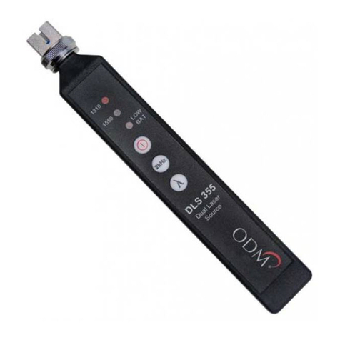
Ripley Miller DLS360 User manual

Page 1
DLS360 User Guide
DLS360
Dual Laser Source
User Guide

Page 2
DLS360 User Guide
Contents
Introduction 3
Device Overview 3
Important Safety Information 4
Basic Testing 5
Using 2kHz 6
Maintenance 6
Certications and Contact Information 7

Page 3
DLS360 User Guide
The DLS360 dual Laser source is a low cost compact multimode test Laser used for verifying the proper function of ber
optic networks. This document will serve as an overview of the major features and functions of the device and will oer
tips for troubleshooting common issues in optical networks.
Introduction
Wavelength Indicator
This unit oers 1490nm and 1625nm wavelengths. When the DLS360 is turned on, the red
light indicates which wavelength is selected. The red light will blink to indicate when the
2khz modulation is turned ON.
Power Button
Press this button to turn the DLS360 ON and OFF. The unit will turn o automatically after
15 minutes by default. To disable this timeout hold the power button for at least 5 seconds
when turning ON.
2kHz Button
Toggles 2kHz tone on the currently-selected wavelength. This is usefull for detecting which
ber is being tested at the other end however the modulation reduces output power by
Wavelength Button
cycles through either 1490nm or 1625nm wavelengths
Low Battery Indicator
This indicator light will light up when the CR2 battery needs to be replaced.
Do Not Stare Into Beam
Laser Radiation
DO NOT STARE INTO BEAM
CFR 1040.10
IEC 60825-1:2014-05
Class 1 Laser Product
Connector Adapter
The DLS360 comes with an SC screw-on adapter by default, however additional adapters
are available and are user replaceable.
Device Overview

Page 4
DLS360 User Guide
Important Safety Information
Read and understand all of the instructions and safety
information in this manual before operating this tool.
Laser Hazard
Avoid eye exposure to open ber connectors and interfaces
when working with ber systems. They may be connected to
a live laser source.
Do not look into the output port of a laser source.
Point ber endfaces toward non-reective surfaces to
prevent reection of laser.
Electric Shock Hazard
Pay attention to proper battery polarity. Do not mix battery
types or manufacturers.
Do not open the unit with the exception of the battery
compartment door.
Use this unit only for its intended purpose as outlined in this
document.
Damage to Item Hazard
Do not leave item in direct sunlight or near heat sources,
submerge in water, or subject unit to strong impact.
Cover the ber interface with the ip-cap when not in use.
Do not throw this product away.
Contact your local recycling station to dispose of properly.

Page 5
DLS360 User Guide
Basic Testing
The DLS360 is calibrated to have an output power level of -5dBm. Variations in power level
between -5dBm and -8dBm may be normal depending on the quality and age of the test jumper, the DLS360 output port,
and other factors.
Always ensure the DLS360 is transmitting an acceptable power level before performing an insertion loss test. Simply insert
the test jumper (plugged into the DLS360) into a companion power meter set to the dBm mode. The power meter will
indicate the measured output power of the Laser. If this reading is not near -5dbm rst inspect the DLS360 ferrule with an
Inspection Scope. If it passes according to IEC try using a dierent test jumper. If none of these resolve your issue please
contact Tech support -see the nal page of this document for contact information.
Transmitting Light
The DLS360 transmits either the 1490nm or 1625nm wavelength on Multimode ber. Be sure to use a test jumper to
mate the DLS360 to the ber under test. this allows you to isolate the DLS360 from any dirt on the ber being tested and
allows you to set reference when doing relative power tests.
Test Jumper
Mate Connectors
Signal Propagates Down
the Fiber
Caution: Invisible Laser Radiation
Please note that 1490nm and 1625nm wavelengths are not visible to the human eye. Do not look directly into the output
port of the DLS360 or directly into any ber connector that may be live.
Since the Laser is invisible to the eye, the eye’s natural blink reex is suppressed. This can cause damage to the retina.
FDA 21 CFR 1040.10 and 1040.11
IEC 60825-1: 2007-03
Class 1 Laser Product
Output Power
Power Meter Displays
Output Power of Laser
Test Jumper Plugged
Into Power Meter

Page 6
DLS360 User Guide
To output a 2kHz tone simply turn the device on, select your desired wavelength, then press the “2kHz” button. The
wavelength indicator will begin blinking to conrm to the user that 2kHz tone is being output. Plugging in a power meter
like the RP450 will display an onscreen notication and output a loud beep to alert the user at the other end that a tone
has been detected. To disable the tone simply press the 2kHz button again.
Using 2kHz
Maintenance
The DLS360 utilizes a physical ber connection at the output port. This ensures a steady power level for performing
insertion loss tests.
Be aware that any test jumpers must be inspected and cleaned before plugging into the DLS360 unit. If soiled or damaged
connectors are inserted, they can cause damage to the DLS360 output port and the unit may need to be repaired.
The test jumper has
physical contact with the
ferrule inside the DLS360.
To clean the ferrule
inside the DLS360:
• Unplug the test jumper
• Unscrew the adapter until it spins
freely, then pull
• Inspect the ferrule with an
approved microscope, clean if
necessary, and replace adapter
Caring for the DLS360 Output Port
Singlemode bers usually have either blue (UPC) or green (APC) connectors. The DLS360 Laser source uses a UPC
connector so neither beige nor green connectors are appropriate.
DO NOT plug an APC connector into the DLS360 unit. This can cause irreparable damage to
both connectors.

Page 7
DLS360 User Guide
Light Source Accessories
Light Source Adapters
Part Number Description
AC 022B SC Adapter
AC 023B FC Adapter
AC 024B ST Adapter
AC 025B LC Adapter
Patch Cord Accessories
Part Number Description
AC 550 MM SC-LC - 1m simplex
AC 551 MM SC-SC - 1m simplex
AC 552 MM LC-LC - 1m simplex
AC 600 SC-SC simplex bulkhead
AC 601 LC-LC simplex bulkhead
Certications, and Contact Information
The DLS360 comes calibrated and should be recalibrated every 2 years. Included with the DLS360 is a calibration
certicate, and free recalibration within 2 years of the date of purchase. To start the calibration process simply call or email
technical support!
Calibration Certicates
The DLS360 comes with a 2 year warranty for any manufacturer defects or damage due to reasonable use. o start the RMA
process simply email or call technical support!
Warranty
Specifications
LASER SOURCE
Wavelength 1490 & 1625
Output Power -5.0 dBm
Output Stability ±0.05dB (1 Hour)
±0.03dB Long-Term (15 min warm-up)
Spectral Width 5nm
Optical Interface SC/FC/ST/LC Interchangeable
Tone Output 2 kHz
Laser Class Class 1 (FDA 21 CFR 1040.11)
Power Push Button Toggle
Battery CR2
Operating Temperature -10° to +50° C
Storage Temperature -30° to +60° C
Dimensions 15.5cm x 2.38cm x 1.9cm
Weight 3 oz

Page 8
DLS360 User Guide
Certications and Contact Information
This product conforms with health, safety, and
environmental protection standards for products sold within
the European Economic Area (EEA). This product was tested
by an ISO 17025 accredited laboratory and complies with
the following CE directives and standards listed below:
Directives:
Electromagnetic Compatibility (2014/30/EU)
Low-Voltage (2014/35/EU)
Standards:
EMC: EN 61326-1:2013 Industrial
Safety: EN/IEC61010-1:2010+A1:2016
This device complies with Part 15 of the FCC Rules. Operation is
subject to the following two conditions: (1) this device may not cause
harmful interference, and (2) this device must accept any interference
received, including interference that may cause undesired operation.
This equipment has been tested and found to comply with the limits
for a Class B digital device, pursuant to part 15 of the FCC Rules.
These limits are designed to provide reasonable protection against
harmful interference in a residential installation. This equipment
generates, uses and can radiate radio frequency energy, and if not
installed and used in accordance with the instructions, may cause
harmful interference to radio communications. However, there is no
guarantee that interference will not occur in a particular installation. If
this equipment does cause harmful interference to radio or television
reception, which can be determined by turning the equipment o
and on, the user is encouraged to try to correct the interference by
one or more of the following measures:
• Reorient or relocate the receiving antenna.
• Increase the separation between the equipment and receiver.
• Connect the equipment into an outlet on a circuit dierent from
that to which the receiver is connected.
• Consult the dealer or an experienced radio/TV technician for help.
Contact us with any questions pertaining to this or any other Ripley product.
Call Us:
(603) 524-8350
Email Us:
tec[email protected]y-tools.com
Visit Us Online: www.ripley-tools.com
Contact Support
Table of contents
Other Ripley Measuring Instrument manuals
Ripley
Ripley Miller RP450 User manual

Ripley
Ripley ODM RP 460 User manual

Ripley
Ripley Miller UPM100 User manual

Ripley
Ripley ODM VIS 500 User manual

Ripley
Ripley ODM RP 460 User manual

Ripley
Ripley MILLER DLS 655 User manual

Ripley
Ripley MILLER VIS300 User manual
Ripley
Ripley ODM DLS 355 User manual

Ripley
Ripley ODM OTDR 800 User manual

Ripley
Ripley ODM DLS 360 User manual