Ripley MILLER DLS 655 User manual

DLS 655
Multi Light Source
User Guide

Page 2
DLS655 User Guide
Contents
Introduction 3
Device Overview 3
Important Safety Information 4
Understanding the Main screen 5
Modes 6
Settings 7
Dual Adapter Light Sources 8
Certications and Contact Information 9

Page 3
DLS655 User Guide
Introduction
Device Overview
The DLS 655 is an optical laser source used for verifying the proper function of ber optic networks.
This document will serve as an overview of the major functions and features of the device.
Protective Adapter Cover
Cover ips closed to protect ber interface when storing DLS 655.
When ipped open, cover may be used to prop DLS 655 on a at
surface.
LCD Screen
Screen displays all relevant information for ber testing. Backlight
timer may be adjusted in device options menu.
Laser Button
On Main screen, press button once to toggle laser ON and OFF.
OK/Menu Button
Used to access menu system and select settings within menus.
Directional Buttons
Used to navigate menu system or select outputs on dual adapter
models.
Power Button
Press once to turn unit ON or OFF.
Wavelength Switch Button
On Main screen, press button once to switch output wavelength.
Wavelength selection will cycle between single and dual outputs.
Laser and LED Radiation
DO NOT STARE INTO BEAM
CFR 1040.10 and 1040.11
IEC 60825-1:2014
IEC 62471:2006
Class 1 Laser/LED Product
Laser Radiation
DO NOT STARE INTO BEAM
CFR 1040.10 and 1040.11
IEC 60825-1:2014-05
Class 1 LaserProduct

Page 4
DLS655 User Guide
Important Safety Information
Read and understand all of the instructions and safety
information in this manual before operating this tool.
Laser Hazard
Avoid eye exposure to open ber connectors and interfaces
when working with ber systems. They may be connected to
a live laser source.
Do not look into the output port of a Laser.
Point ber endfaces toward non-reective surfaces to
prevent reection of laser.
Electric Shock Hazard
Pay attention to proper battery polarity. Do not mix battery
types or manufacturers.
Do not open the unit with the exception of the battery
compartment door.
Use this unit only for its intended purpose as outlined in this
document.
Damage to Item Hazard
Do not leave item in direct sunlight or near heat sources,
submerge in water, or subject unit to strong impact.
Cover the ber interface with the ip-cap when not in use.
Do not throw this product away.
Contact your local recycling station to dispose of properly.

Page 5
DLS655 User Guide
Laser ON
nm
1310
Laser ON
nm
1550
Dual2kHz
Understanding the Main screen
Battery Indicator
The battery indicator displays
the current battery level. When a
single square segment remains, the
batteries have less than 25% power
and should be replaced.
Laser Indicator
When the laser is ON, the laser
symbol will be displayed in this
segment of the screen.
Laser/LED 1 Indicator
Displays whether the rst
wavelength is ON or OFF.
Laser/LED 2 Indicator
Displays whether the second
wavelength is ON or OFF.
Tone Indicator
Displays 2kHz, 1kHz, or 270Hz, if one
of those modulated tones is being
transmitted.
Wavelength 1 Display
The wavelength that is currently
being transmitted is displayed here.
Wavelength 2 Display
The second wavelength that is
currently being transmitted is
displayed here.
Dual Mode Indicator
The word “Dual” is shown when two
wavelengths are being transmitted
simultaneously.
The Main screen of the DLS 655 acts as the general user interface for ber testing.
Up to two wavelengths may be transmitted on a single output port at the same time.
When a single wavelength is selected for transmission, only that wavelength will be shown onscreen.
Both wavelengths will be shown onscreen only when they are both selected for transmission.

Page 6
DLS655 User Guide
Modes
Press the OK/Menu button to access the Main Menu
Use the Up/Down arrow buttons to move the cursor to the option you would like to explore. Press the
Left arrow button to go back to the Main screen. Press the OK/Menu button or the Right arrow button
to select an option.
Press the OK or Right arrow button to select the Mode menu.
The Mode menu shows all modulation modes the DLS 655 can
transmit.
CW indicates the continuous wave mode. This mode contains
no modulation. CW mode can be used with any optical power
meter.
Wave-ID indicates the automated wavelength identication
mode. In this mode, the DLS 655 wavelength information is
transmitted and can be recognized by the RP 560-series of
optical power meters. The RP 560 will automatically switch to
measure the wavelength being transmitted.
2kHz, 1kHz, and 270Hz are all modulated signals that may be
needed for continuity testing on ber. Any Ripley power meter
will identify a 2kHz tone, but the 1kHz and 270Hz options are
only compatible with the RP 560-series.
The currently-selected option is highlighted.
Main Menu
Mode
Backlight
Mode
CW
Wave-ID
2kHz
1kHz
270Hz

Page 7
DLS655 User Guide
Settings
Press the OK/Menu button to access the Main Menu
Use the Up/Down arrow buttons to move the cursor to the option you would like to explore. Press the
Left arrow button to go back to the Main screen. Press the OK/Menu button or the Right arrow button
to select an option.
Press the OK or Right arrow button to select the Backlight menu.
The backlight menu displays the options for the screen light
timer.
Use the Up/Down arrow buttons to move the cursor to the
option you would like to select.
Use the OK/Menu or Right arrow button to activate the option.
The currently-selected option will be highlighted.
The backlight will turn on each time a button is pressed on the
DLS 655. The timer option indicates how long it is illuminated.
Main Menu
Mode
Backlight
Backlight
Off
5 sec
15 sec
30 sec

Dual Adapter Light Sources
Right Adapter/Port
Output port for light source
indicated by “Right” on display.
Left Adapter/Port
Output port for light source
indicated by “Left” on display.
Left Adapter/Port Indicator
Indicates Left output port is
currently active/selected
Right Adapter/Port Indicator
Indicates Right output port is
currently active/selected
On Dual Adapter/Quad light sources, only one output can be active at a time.
The currently active/enabled output will be indicated on the main display by “Right” or “Left” as
shown below.
Press the Left arrow button while on the main screen to switch to the Left output.
Press the Right arrow button while on the main screen to switch to the Right output.
Left Arrow Button
Switches the currently active
output port to Left
Right Arrow Button
Switches the currently active
output port to Right

Page 9
DLS655 User Guide
Accessories
Light Source Adapters
PART NO. DESCRIPTION
AC 022B SC Adapter
AC 023B FC Adapter
AC 024B ST Adapter
Patch Cord Accessories
PART NO. DESCRIPTION
AC 500 SM SC-LC - 1m Simplex
AC 501 SM SC-SC - 1m Simplex
AC 502 SM LC-LC - 1m Simplex
AC 600 SC-SC Simplex Bulkhead Adapter
Cleaning Tools
PART NO. DESCRIPTION
AC 089 One-Click Cleaner for 1.25mm & ODC Ferrules / Bulkheads
AC 099 One-Click Cleaner for 2.5mm Ferrules / Bulkheads
AC 090 1.25mm Swabs (100 per Pack)
AC 091 2.5mm Swabs (100 per Pack)
AC 092 SqR Pad & Fiber Wash Pen
AC 190 Cletop Cleaner - Type B - Blue Tape
Specifications
SINGLEMODE/MULTIMODE LIGHT SOURCE
Wavelength Several options available, see chart below
Output Power -5.0 dBm (SM), -22.0 dBm (MM)
Output Stability ±0.05dB (1 Hour)
±0.03dB Long-Term (15 min warm-up)
Spectral Width 5nm (SM), 40nm / 120nm(MM)
Optical Interface SC/FC/ST/LC Interchangeable
Tone Output 2 kHz, 1kHz, 270Hz
Class Class 1 (FDA 21 CFR 1040.11) (SM),
Class 1 (IEC 62471:2006)(MM)
Power Push Button Toggle
Battery AA - 2 Alkaline Batteries Included
Operating Temperature -10° to +50° C
Storage Temperature -30° to +60° C
Ordering Information
PART NO. WAVELENGTHS DESCRIPTION
DLS655 1310nm & 1550nm Singlemode dual wavelength laser source
DLS655-01 1310nm, 1490nm, & 1550nm Singlemode triple wavelength laser source
DLS655-02 1310nm, 1550nm, & 1625nm Singlemode triple wavelength laser source
DLS655-03 1490nm & 1625nm Singlemode dual wavelength laser source
DLS655-04 1550nm & 1650nm Singlemode dual wavelength laser source
DLS655-05 850nm, 1300nm, 1310nm, & 1550nm Singlemode and Multimode quad laser source
DLS655-06 1310nm, 1550nm, 1490nm & 1625nm Singlemode quad wavelength laser source

Page 10
DLS655 User Guide
Certications and Contact Information
This product conforms with health, safety, and
environmental protection standards for products sold within
the European Economic Area (EEA). This product was tested
by an ISO 17025 accredited laboratory and complies with
the following CE directives and standards listed below:
Directives:
Electromagnetic Compatibility (2014/30/EU)
Low-Voltage (2014/35/EU)
Standards:
EMC: EN 61326-1:2013 Industrial
Safety: EN/IEC61010-1:2010+A1:2016
This device complies with Part 15 of the FCC Rules. Operation is
subject to the following two conditions: (1) this device may not cause
harmful interference, and (2) this device must accept any interference
received, including interference that may cause undesired operation.
This equipment has been tested and found to comply with the limits
for a Class B digital device, pursuant to part 15 of the FCC Rules.
These limits are designed to provide reasonable protection against
harmful interference in a residential installation. This equipment
generates, uses and can radiate radio frequency energy, and if not
installed and used in accordance with the instructions, may cause
harmful interference to radio communications. However, there is no
guarantee that interference will not occur in a particular installation. If
this equipment does cause harmful interference to radio or television
reception, which can be determined by turning the equipment o and
on, the user is encouraged to try to correct the interference by one or
more of the following measures:
• Reorient or relocate the receiving antenna.
• Increase the separation between the equipment and receiver.
• Connect the equipment into an outlet on a circuit dierent from
that to which the receiver is connected.
• Consult the dealer or an experienced radio/TV technician for help.
Contact us with any questions pertaining to this or any other Ripley product.
Call Us:
() -
Email Us:
tec[email protected]y-tools.com
Visit Us Online: www.ripley-tools.com
Contact Support
Table of contents
Other Ripley Measuring Instrument manuals
Ripley
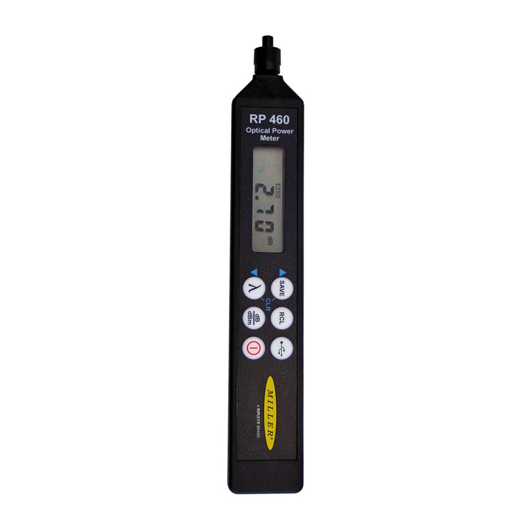
Ripley ODM RP 460 User manual
Ripley
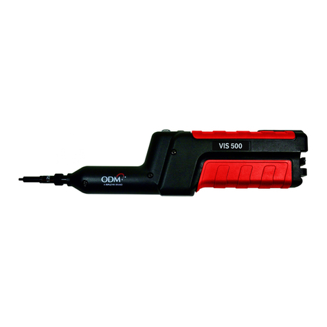
Ripley ODM VIS 500 User manual

Ripley
Ripley Miller UPM100 User manual

Ripley
Ripley Miller DLS360 User manual

Ripley
Ripley ODM RP 460 User manual

Ripley
Ripley MILLER VIS300 User manual

Ripley
Ripley ODM OTDR 800 User manual
Ripley
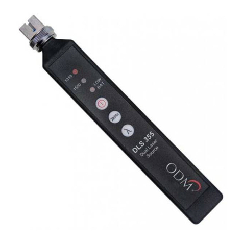
Ripley ODM DLS 355 User manual
Ripley
Ripley ODM DLS 360 User manual

Ripley
Ripley Miller RP450 User manual
Popular Measuring Instrument manuals by other brands
Eno Scientific
Eno Scientific 2010 user manual
Endress+Hauser
Endress+Hauser Proline Promass S 100 technical information
Sentry
Sentry ST 723 instruction manual
Nikon
Nikon Laser 550 user manual
Applent Instruments
Applent Instruments AT2811 user guide

LOVATO ELECTRIC
LOVATO ELECTRIC DME D120 T1 instruction manual
