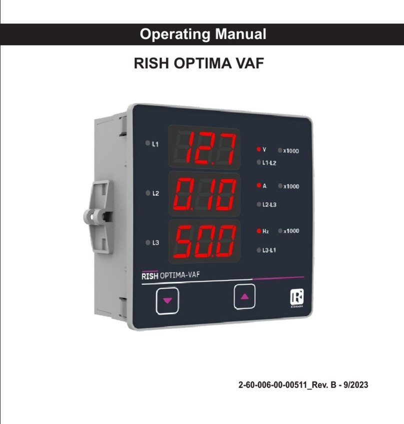
Rish DELTA VAF NX User manual

RISH DELTA VAF NX
Operating Manual
AMAN-00IM-0118_Rev.D - 11/2023

Section Contents
1. Introduction
2. Measurement Reading Parameters
3. Programming
3.1 Password Protection
3.2 Menu Selection
3.2.1 System Parameter Selection Screen
3.2.1.1 System Type
3.2.1.2 Potential Transformer Primary Value
3.2.1.3 Potential Transformer Secondary Value
3.2.1.4 Current Transformer Primary Value
3.2.1.5 Current Transformer Secondary Value
3.2.1.6 Noise Cutoff
3.2.1.7 Demand Integration Time
3.2.1.8 Auto Scrolling
3.2.1.9 No. of Poles Selection
Installation & Operating Instructions
DIGITAL MULTIFUNCTION INSTRUMENT
Programmable Multi-function Digital Panel Meter
3.2.2 Communication Parameter Selection Screen
3.2.2.1 Address Setting
3.2.2.2 RS 485 Baud Rate
3.2.2.3 RS 485 Parity Selection
3.2.3 Reset Parameter Selection Screen
3.2.3.1 Resetting Parameter
3.2.4 Output Option Selection Screen (Menu)
3.2.4.1 Configuration of Output
3.2.4.1.1 Relay Output Selection Menu
3.2.4.1.1.1 Limit output
3.2.4.1.1.1.1 Assignment of Limit Output to Parameter
3.2.4.1.1.1.2 Limit Configuration Select
3.2.4.1.1.1.3 Trip point selection
2

Run-Hour
5. On-Hour
6. Number of Interruption
7. Negative Sign Indication
Relay Output
8.
8.1 Limit Switch
RS 485 (ModBus) Output
9.
9.1 User Assignable Modbus Register
Phasor Diagram
10.
11. Installation
EMC Installation Requirements11.1
11.2 Case Dimensions and Panel Cut-out
11.3 Wiring
11.4 Auxiliary Supply
11.5 Fusing
11.6 Earth / Ground Connections
12. Connection Diagrams
13. Specification
3
3.2.4.1.1.1.4 Hysteresis selection
3.2.4.1.1.1.5 Energizing delay time
3.2.4.1.1.1.6 De-energizing delay time
3.2.5 Quit screen
4.

1. Introduction
4
DOWN Key
UP Key
The Multifunction Meter is a panel mounted 96 x 96mm DIN Quadratic Digital Panel
Meter, which measures important electrical parameters in 3P4W, 3P3W, 1P3W (Split
Phase) and 1P2W networks and replaces the multiple analog panel meters. It measures
electrical parameters like AC Voltage, Current, Frequency, Power Factor, The instruments
comes with 3 Line 4 Digits ultra bright LED display with clearly visible annunciated units
with bright LED Indications. The Multifunction Meter can be configured & programmed on
site for the following: PT Primary, PT Secondary, CT Primary, CT Secondary & System
Type (P4W/3P3W/1P3W/1P2W).
The front panel has two Keys for user interface to scroll through the available parameters.
The function of the up and down keys are explained in the following page.

1. :- UP Key scrolls through L1 Voltage, L2 Voltage, L3 Voltage, L12 Voltage, L23
Voltage, L31 Voltage, L1 Current, L2 Current, L3 Current, , System Neutral Current
RPM, System Frequency, L1 Power Factor, L2 Power Factor, L3 Power Factor, System
Voltage, System Current, System Power Factor, Maximum System Voltage, Maximum
System Current, Minimum System Voltage, Minimum System Current, Run hour, On
hour, Number of Interruptions and back to L1 Voltage.
2. :- DOWN Key scrolls in the reverse direction
The Multifunction meter comes with 14mm display and units annunciated from back
side, which enables to conventional take reading from long distance. The problem with
LED annunciators is also overcome in this Multifunction meter.
5

TABLE 1: Measured Parameters
6
√: Available x: Not Available
2. Measurement Parameters
Sr.
No. Parameter 3 Phase 4
Wire
3 Phase 3
Wire
1 Phase 2
Wire
1 Phase 3
Wire
1 System Voltage
2 System Current
3 Voltage L1
4 Voltage
L2
5 Voltage
L3
6 Voltage
L12
7 Voltage
L23
8 Voltage
L31
9 Current
L1
10 Current
L2
11 Current
L3
12 Frequency
13 System
Power
Factor
14 Power
Factor
L1
15 Power
Factor
L2
16 Power
Factor
L3
17 RPM
18 Min
and
Max
System
Voltage
19 Min
and
Max
System
Current
20 Run
Hour
21 On
Hour
22 Number
of
interruptions
23 Neutral Current

: UP Key
: DOWN Key
Setup Parameter Screens
SEL (Select)
Out PArA
(Output Parameter)
(Exit Menu)
rESEt
(Reset Parameter)
Ser PArA
(Serial Comm.Parameter)
Addr
(Modbus Address)
br
(Baud Rate)
Pr
(Parity Bits)
CodE (PassWord)
SYS PArA
(System Parameter)
(Sec 3.2.1) (Sec 3.2.2) (Sec 3.2.3) (Sec 3.2.4)
(Sec 3.2.2.1)
(Sec 3.2.2.2)
(Sec 3.2.2.3)
SYS
(System Type / Network)
UP
(PT Primary)
US
(PT Secondary)
AP
AS
Auto
(Auto Scrolling)
(Sec 3.2.1.1)
(Sec 3.2.1.2)
(Sec 3.2.1.3)
(Sec 3.2.1.4)
(Sec 3.2.1.5)
(Sec 3.2.1.9)
POLE
(No. of poles selection)
(Sec 3.2.1.8)
(CT Primary)
(CT Secondary)
Ser quit
none (No Parameter),
ALL (All Parameters),
hi (Max values),
Lo (Min values),
hr
(Run Hr. & On Hr.),
Intr (No. of Interrupts)
Select any one option
using “ ” key.
Exit from setup parameter to Main Display
Lt
(Limit Output)
(Para Selection)
(High,Low)
triP
10% to 100%
HYS
(Hysterisis)
0.5% to 50%
(Sec 3.2.4.1.1.2)
(Sec 3.2.4.1.1.2.1)
(Sec 3.2.4.1.1.2.2)
(Sec 3.2.4.1.1.2.4)
LiM-N PArA
(Limit Config Selection)
LiM-N Alrm
(Trip Point)
En-d
(Energizing Delay time)
1s to 10s
(Sec 3.2.4.1.1.2.5)
quit
(Exit Menu)
" "
" "
" "
" "
" "
" "
" "
" "
" "
" "
" "
" " " "
" " " " " " " " " "
" "
" "
dE-d
(De-energizing Delay time)
1s to 10s
(Sec 3.2.4.1.1.2.6)
" "
" "
" "
" "
" "
" "
(Sec 3.2.4.1.1.2.3)
" "
(Relay)
(Sec 3.2.4.1)
rEL1
(Exit Menu)
quit
" "
(Exit Menu)
Sys quit
B
nonE
(None Output)
" "
B
" "
C B
rEL1 quit
(Relay 1 Quit)
" " " "
C
" "
" "
" "
" "
" "
" "
7
d (Max demand)
ncrt
(Noise Cutoff)
(Sec 3.2.1.6)

3.1. Password Protection
Password protection can be enabled to
prevent unauthorised access to set-up
screens, by default password protection
is not enabled. Password protection is
enabled by selecting a four digit number
other than 0000, setting a password of
0000 disables the password protection.
Enter Password,
prompt for first digit.
(Blinking digit denotes
that value will be
changing). Press the
“ ” key to scroll the
value of first digit from
0 through to 9, the
value will wrap from 9 round to 0. Press
the “ ” key to advance to next digit. In
special case where the Password is “0000”
pressing the “ ” key when prompted for
the first digit will advance to “Password
confirmed” screen.
Enter Password, first
digit entered, prompt
for second digit.
(Blinking digit denotes
that value will be
changing).
3. Programming
The following sections comprise step by step procedures for configuring the Multifunction
Meter for individual user requirements.
To access the set-up screens press and hold the “ ” and “ ” key simultaneously for 5
seconds. This will take the user into the password protection entry stage (section 3.1).
A
M K W h
V
A
Kr h
K
V
M
L1
L2
DM
L3
A h
L3 L1 Hz P F
SY
8
Use the “ ” key to scroll the value of the second
digit from 0 through to 9.
the value will wrap from 9 round to 0. Press the
“ ” key to advance to next digit. Enter Password,
second digit entered, prompt
for third digit. (Blinking digit
denotes that value will be
changing). Use the “ ” key
to scroll the value of the third
digit from 0 through to 9, the
value will wrap from 9 round
to 0.
Press the “ ” key to advance to next digit. Enter
Password, third digit entered, prompt for fourth
digit. (Blinking digit denotes that value will be
changing).Use the “ ” key
to scroll the value of the
fourth digit from 0 through
to 9, the value will wrap from
9 round to 0. Press the “ ”
key to advance to verification
of the Password.

Enter Password, fourth
digit entered, awaiting
verification of the password.
Pressing “ ” key will
advance to the “New/Change
Password” entry stage.
Pressing the “ ” key will
advance to the menu selection
screen. (See Section 3.2).
Password confirmed.
Pressing the “ ” key to advance the operation
to the next digit and sets the first digit, in this case to “2”
New/Change Password, first
digit entered, prompting for
second digit. (Blinking digit
denotes that value will
be changing).
(Blinking digit denotes
that value will be changing)
Pressing the “ ” key will
scroll the value of the first
digit from 0 through to 9,
the value will wrap from
New / Change Password
The meter has not accepted
the password entered.
Pressing the “ " key
will return to the enter
password stage.
Pressing the “ ” key exits
the password menu &
Password Incorrect.
Pressing the “ ” key will
scroll the value of the second
digit from 0 through to 9, the
VSys
A
M K W h
V
A
Kr h
V
M
L1
L2
DM
L3
A h
L3 L1 Hz P F
SY
V
V
M
L2
DM
SY
New / Change Password,
second digit entered,
prompting for third digit.
(Blinking digit denotes
that value will be changing).
Pressing the “ ” key
will scroll the value of the third digit from 0 through
to 9, the value will wrap from 9 round to 0.
New/ Change Password,
third digit entered, prompting
for fourth digit. (Blinking
digit denotes that value
will be changing).
Pressing the “ ” key will
scroll the value of the fourth
digit from 0 through to 9,
returns operation to the measurement
reading mode.
value will wrap from 9 round to 0.
the value will wrap from 9 round to 0. Pressing the “ ”
key to advance the operation to the new password
confirmed” & sets the fourth digit in this case to “3”.
Pressing the “ ” key to advance the operation to the
next digit and sets the third digit, in this case to “5”
Pressing the “ ” key to advance the operation to the
next digit and sets the second digit, in this case to “1”
9
9 round to 0.

Pressing the “ ” key will
return to the “New/Change
Pressing the “ ” key will
advances to the Menu
Selection screen (See
Section 3.2).
New Password Confirmed
3.2 Menu Selection
3.2.1 System Parameter Selection Screen
This screen is used to select
the different system parameter
like “System Type”, “CT
Pressing the “ ” key allows
the user to select & configure
the output option (See Section
VSys
A
A
K
L2 M L3 W Ø
r h
V
L1 A h
SY
V
V
A
K
L2 M L3 W Ø
r h
K
V
M
L1
L2
DM
L3
A h
SY
Pressing the “ ” key
Ratio”, “PT Ratio”, pressing
the “ ” key allows the user
to set different system
parameters (See Section
3.2.2 Communication Parameter
Selection Screen
This screen is used to select
the different communication
parameters like “Address ”,
”RS485 Parity” and ”RS485
Baudrate”.
Pressing the “ ” key allows the
user to set different
communication parameters.
3.2.5 Quit Screen
This screen will allow the
user to quit the menu
pressing the “ ” key will
allow the user to quit from
menu & return to
measurement screen.
Pressing the “ ” key will advance to Communication
Parameter Selection screen (See Section 3.2.2).
(See Section 3.2.2.1 to 3.2.2.3). Pressing the “ ”
key will advance to Reset Parameter screen.
(See Section 3.2.3).
3.2.3 Reset Parameter Selection Screen
This screen is used to reset
the different parameters.
Pressing the “ ” key allows
the user to reset different
system parameters
(See Section 3.2.3.1).
Pressing the “ ” key
PE
A
V
A
Kr h
K
V
M
DM
L3
A h
SY
will advance to Output Option Selection screen
(See Section 3.2.4).
3.2.4 Output Option Selection Screen
This screen will allow the
user to select output option
like “Relay” Output.
key will advance to Quit screen. (See Section 3.2.5)
will advance to System Parameter selection
screen (See Section 3.2.1).
10
Password ”.
3.2.1.1 to 3.2.1.7).
3.2.4.1). Pressing the “ ”

VSys
E
M K W h
V
A
K
L2 M L3 W Ø
r h
K
V
M
L1
L2
DM
L3
A h
L3 L1 Hz P F
SY
3.2.1.1 System Type
3.2.1 System Parameters Selection
This screen is used to set the
System Type 3P4W, 3P3W,
1P3W & 1P2W.
Pressing the “ ”key advances to
the “Potential Transformer
Primary Value” screen (See
Section 3.2.1.2).
Pressing the “ ” key
advances to the “Potential
Transformer Secondary Value”
screen (See Section 3.2.1.3).
Initially the “multiplier must be selected, pressing the
“ ” key will move the decimal point position to the
right until it reaches # # #.# after which it will return
to #. # # #.
Pressing the “ ” key accepts the present multiplier
(decimal point position) and advances to the
Potential Transformer Primary digit edit mode.
Note: PT Values must be set as Line to
Line Voltage for Primary as well as
Secondary for all System Types
(3P3W/3P4W/1P3W/1P2W).
Pressing the “ ”
key will scroll the value of the
most significant digit from 0
through to 9.
Pressing the “ ” key will enter the System Type
edit mode & further pressing of “ ” scroll the
values through values available.
Pressing the “ ” key again sets the displayed
value and pressing ” ” key will advance to
“Potential Transformer Primary Value” screen.
(See section 3.2.1.2)
Transformer Primary Value edit mode.
Pressing the “ ” key accepts the present value at the
cursor position and advances the cursor to the next
less significant digit.
11
3.2.1.2 Potential Transformer
Primary Value
The nominal full scale voltage which will be
displayed as the Line to Line voltages for all system
types. The values displayed represent the voltage
in kilovolts (note “K” annunciator).
Pressing the “ ” key
will enter the Potential
The PT Primary value can be set from 100VL-L to
1200 kVL-L.
Note: The flashing decimal point indicates the cursor
position, a steady decimal point will be present to
identify the scaling of the number until the cursor
position coincides with the steady decimal point
position. At this stage the decimal point will flash.

When the least significant digit has been set pressing
the “ ” key will advance to the Potential Transformer
Primary Value confirmation stage.
Screen showing display of 0.120 kV i.e. 120 Volts
indicating steady decimal point and cursor flashing
at the “hundreds of volts” position.
Pressing the “ ” key sets the displayed value and
will advance to the “Potential Transformer Secondary
Value” screen (See Section 3.2.1.3).
3.2.1.3 Potential Transformer
Secondary Value
The value must be set to the nominal full scale
secondary voltage which will be obtained from
the Transformer when the potential transformer
(PT) primary is supplied with the voltage defined
in 3.2.1.2 potential transformer primary voltage.
Pressing the “ ” key accepts the present value at the
cursor position and advances the cursor to the next .
The ratio of full scale primary to full scale secondary
is defined as the transformer ratio.
The PT Secondary value can be set from 100VL-L
to 500VL-L.
12
If the scaling is not correct, pressing the “ ” key
will return to the “Potential Transformer Primary digits
flashing indicating Value Edit” stage with that multiplier
(decimal point position) should be selected.
.
less significant digit
L3 L1 Hz P F
If the scalling is not correct, pressing the “ ” key
will return to the “Potential Transformer Secondary
Value Edit screen.
A
M K W h
V
A
Kr h
K
V
M
L1
L2
DM
L3
A h
L3 L1 Hz P F
SY
.
.
Pressing the “ ” key sets the displayed value and “ ”
key will advance to the "Current Transformer Primary
Value" screen (See Section 3.2.1.4).
3.2.1.4 Current Transformer Primary Value
The nominal Full Scale Current that will be displayed
as the Line currents. This screen enables the user to
display the Line currents inclusive of any transformer
ratios, the values displayed represent the Current in
Amps.
Pressing the “ ” key will
enter the Current Transformer
Primary Value edit mode.
This will scroll the value of the
most significant digit from 0
through to 9
Pressing the “ ” key will advance to the next less
significant digit. (* Denotes that decimal point will
be flashing).
Pressing the “ ” key
advances to the Current
Transformer Primary Value”
screen (See Section 3.2.1.4).
Transformer Secondary Value edit mode.
Pressing the “ ” key
will enter the Potential
Pressing the “ ” key advances to the Current
Transformer Secondary Value” screen (See Section
3.2.1.5).
The minimum value allowed is 1, the value will be
forced to 1 if the display contains zero when the “ ”
key is pressed.
If the scaling is not correct, Pressing the “ ” key will
return to the Current Transformer Primary Value edit
stage with the most significant digit highlighted
(associated decimal point flashing) and the bottom
line of the display will be blanked.
The CT Primary value can be set from 1A
to 9999A.

13
VA
Kr h
KV
M
L1 L2
DM
A h
SY
3.2.1.5 Current Transformer Secondary Value
This screen is used to set the
value for Current Transformer
Secondary value, “5” for 5A
or “1” for 1A can be selected.
Pressing “ ” key advances
to the Demand Integration
Time (See Section 3.2.1.6).
Pressing the “ ” key will enter the CT Secondary
value edit mode and pressing the “ ” key scroll
the value through the values available.
Pressing “ ” key sets the displayed value and “ key”
will advance to “Noise Cutoff” screen (See
Section 3.2.1.6).
A
M K W h
V
A
Kr h
V
M
L1
L2
DM
L3
A h
SY
V
M K W h
L2 M L3 W Ø
3.2.1.7 Auto Scrolling
VP
A
M K W h
L1
L3 L1 Hz P F
SY
This screen allows user to
enable screen scrolling.
Pressing ” ” key advance
to the No. of Poles Selection
screen (See Section 3.2.1.8).
V
A
r h
K
V
M
L1
L2
DM
L3
A h
SY
Pressing the “ ” key will
enter the Auto Scrolling
Screen edit mode and
toggle the status ‘Yes’ and
‘No’.
Pressing the “ ” key will
select the status displayed
and “ ” key advance to the
No. of Poles Selection screen
(Section 3.2.1.9).
This screen enables to set No. of poles of a Generator
of which RPM is to be measured and to which the
instrument is connected to monitor its parameters.
3.2.1.8 No. of Poles Selection
Pressing “ ” key returns to
System Type Selection
screen (See section 3.2.1.1).
Pressing the “ ” key will
enter the No. of Poles
selection edit mode.
Pressing “ ” key scroll the number from
02 to 40 in step of 2. After 40 it scrolls the
number again to 02.
Pressing “ ” key set the number on screen as
number of poles of generator & “ ”key
advance to System exit selection menu.
This screen allows the
user to set Low noise
current cutoff in mA.
Pressing " " key
advances to the Auto
scrolling.
3.2.1.6 Noise cutoff
Pressing " " will enter into the Noise Cutoff
selection edit mode.
r h
DM
SY

14
VA h
3.2.2 Communication Parameter Selection
3.2.2.1 Address Setting
This screen applies to the RS 485
output only. This screen allows the
user to set RS 485 parameter for
instruments.
The range of allowable
address is 1 to 247. Enter
Address, prompt for first digit.
Enter Address, first digit
entered, prompt for second
digit. (Blinking
digit denotes that value
will be changing).
Use the “ ” key to scroll
the value of the second digit.
Enter Address, second digit
entered, prompt for third digit.
(Blinking digit denotes
that value will be
changing).
Use the “ ” key to scroll
the value of the third digit.
Press the “ ” key to advance to next digit.
Press the “ ” key to scroll the value of the first digit.
Enter Address for third digit.
Press the “ ” key to advance
to next Screen “RS485 Baud
Rate” (See Section 3.2.2.2).
Pressing the “ ” key will
re-enter the Address edit mode.
This screen allows the user
to set Baud Rate of RS 485 port.
The values displayed on
screen are in kbaud.
Pressing “ ”key advance to the
Parity Selection screen (See
Section 3.2.2.3).
3.2.2.2 RS 485 Baud Rate
Pressing the “ ” key will select the value pressing
“ ” key it advances to the Parity Selection screen
(See Section 3.2.2.3).
3.2.2.3 RS 485 Parity Selection
This screen allows the user to set Parity & Number
of Stop Bits of RS 485 port.
Pressing “ ” keys advances
to Serial Parameter Quit screen.
Pressing the “ ” key will enter
the Parity & Stop Bit edit mode
& pressing “ ” key scroll the
value available.
Pressing the “ ” key will enter the Baud Rate
edit mode and pressing “ ” key will scroll the
value through 4.8, 9.6, 19.2, 38.4, 57.6 &
back to 4.8.
odd : odd parity with one stop bit
no 1 : no parity with one stop bit
no 2 : no parity with two stop bit
E : even parity with one stop bit

M K W h
V
A
K
L2 M L3 W Ø
r h
K
V
L1
L2
DM
L3
A h
SY
3.2.3.1 Resetting Parameter
The following screens allow the users to reset Max
demand parameters, Lo (Min) / Hi (Max) values of
voltage & current , Run hour, On hour, No. of Interrupts,
& all the parameters
3.2.3 Reset Parameter Selection
Reset “None” select:
Pressing “ ” key advances
to Reset Parameter
selection screen (See
Section 3.2.3). Pressing
the “ ” key will enter the
Reset option mode & scroll
through parameter and
wrapping back to none.
15
A
V
A
K
L2 M L3 W Ø
r h
K
V
M
L1
L2
DM
L3
A h
SY
Reset option “Lo” select: (Reset
Min parameters). Pressing “ ”
key will select the value and
advance to the reset all Low
parameters.
Reset option “hr” select: (Reset
ON Hour & Run Hour). Pressing
“ ” key will select the value and
will reset On hour & Run Hour.
Reset option “hi” select:
(Reset Max parameters)
Pressing “ ” key will select
the value and resets all
Max parameters.
Sys
V
Kr h
K
V
M
L1
L2
DM
A h
L3 L1 Hz P F
SY
V
Reset option “Intr” select:
(Reset Number of Interrupt)
Pressing “ ” key will select
the value and will reset
number of auxiliary supply
interruption count.
V
E
V
A
K
L2 M L3 W Ø
r h
V
M
L1
L2
DM
L3
A h
SY
Reset option “All” select:
(Resets ALL resettable parameter)
Pressing “ ” key will select
the value and advance to the
reset ALL parameters.
M K W h
L1 L2
DM
L3
SY
Pressing the “ ” key will
set the value.
Pressing the “ ” key again
will jump to the Serial
parameter Quit screen.
Reset option "d" select:
(Reset Max Demand
parameters)
Pressing " " key will
select the value and
resets all Max Demand
parameters.

16
3.2.4.1.1 Relay output Selection Menu
3.2.4.1.1.1 Limit Output
This screen is used to
assign Relay in limit output
mode.
Pressing “ ” key will assign
Limit output mode (See
Section 3.2.4.1.1.1.1).
Pressing the “ ” key will scroll through Limit or None
None Option.
if None option Selected then the relay will not
assigne to any parameter
This screen allows the user
to quit the output option
V
A
M K W h
V
A
Kr h
V
M
L1
L2
DM
L3
L3 L1 Hz P F
SY
Pressing the “ ” key will
go back to Relay output option
(See section 3.2.4.1).
Pressing “ ” key will advance
to the Output Parameter selection
(See section 3.2.4)
M K W h
V
A
K
L2 M L3 W Ø
r h
K
V
L1
L2
DM
A h
SY
E
P
A
V
A
Kr h
K
V
M
L1
L2
DM
L3
A h
SY
3.2.4. Output Option Selection Menu
This screen applies to the
Relay Output option Selection.
3.2.4.1 Configuration of Output
Pressing the “ ” key will
advance to the Quit screen.
Pressing “ ” key will select
the rEL1 Output Selection
Screen(See Section3.2.4.1.1).
Sys
E
A
VA
K
L2 M L3 W Ø
r h
K
M
DM
L3
A h
SY
3.2.4.1.1.1.1 Assignment of Limit Output
to Parameter
This screen is for Limit output mode selection. It
allows the user to set Limit output corresponding
measured value. Refer Table 2 “Parameter for Limit
Output” for assignment.
Pressing “ ” key advance
to the Limit Configuration
Selection screen (See Section
3.2.4.1.1.1.2). Pressing the “ ”
key will enter the Limit Output
edit mode. Pressing the “ ”
scroll the values, as per Table
2: “Parameter for Limit Output”.
V
PSy
A
M K W h
VA
L2 M W Ø
r h
V
L1
DM
A h
L3 L1 Hz P F
SY
P
A
M K W h
V
K
L2 M L3 W Ø
r h
KV
L1 L2
DM
A h
L3 L1 Hz P F
SY
Pressing the “ ” key sets the displayed value &
pressing “ ” key will advance to the Limit
Configuration Selection screen (See Section
3.2.4.1.1.1.2 ).
(For detail refer to section 8.1).
Pressing the “ ” key advances to the “Trip point selection”
screen (See Section 3.2.4.1.1.1.3).
Pressing the “ ” key will enter the Limit Configuration
edit mode and pressing the “ ” key will scroll through the
modes available.
Hi - E (High Alarm &
Energized Relay)
Hi - d (High Alarm &
De-Energized Relay)
Lo - E (Low Alarm &
Energized Relay)
Lo - d (Low Alarm &
De-Energized Relay)
3.2.4.1.1.1.2 Limit Configuration Select
This screen is used to set the Limit Configuration,
four different types of configuration can be selected:

3.2.4.1.1.1.3 Trip Point Selection
V
A
V
A
r h
K
V
DM
A h
SY
This screen applies to the Trip Point Selection.
This screen allows the user to set Trip point for
the meter.
The first digit entered,
prompt for second digit
(Blinking digit denotes
that value will be
changing).Use the
“ ” key to scroll the
value of the second digit.
V
A
V
A
Kr h
K
M
L1
L2
DM
L3
A h
SY
Press the “ ” key to advance to next digit.
V
A
V
A
K
L2 M L3 W Ø
r h
K
V
L1
L2
DM
L3
A h
SY
The second digit entered,
prompt for third digit
(Blinking
digit denotes that value
will be changing).
Use the “ ” key to scroll
the value of the third digit.
The allowable range
for High Alarm and
Low Alarm can be
referred from table 2.
Enter value, prompt
for first digit. (Blinking
digit denotes that value
will be changing).
Press the “ ” key to scroll the values of the first
digit. Press the “ ” key to advance to next digit.
17
Entered the value for third
digit.
Press the “ ” key to advance
to next Screen
“Hysteresis selection”
(see section 3.2.4.1.1.1.4)
Pressing the “ ” key will
return in edit mode.
VPSys
V
A
Kr h
K
V
L1
L2
DM
L3
A h
SY
Note : In case of lo alarm if trip point is set at 100%
then maximum 20% Hysterisis can be set.
Press the “ ” key to scroll the value of the
first digit Press the “ ” key to advance to next digit.
Hysteresis for Frequency is calculated as % of trip
point span from 40Hz. e.g. If trip point is 50%(55Hz)
and hysteresis is set to 10%, then relay will reset at
53.5Hz [10% of (55 - 40Hz) 15Hz is 1.5Hz. Hence,
55 -1.5= 53.5Hz
3.2.4.1.1.1.4 Hysteresis selection
This screen applies to the Hysteresis selection.
This screen allows the user
to set Hysteresis for relay
output
The allowable range is
0.5% to 50 % of Trip point.
Enter value, prompt for first
digit. (Blinking digit denotes
that value will be changing
The first digit entered, prompt
for second digit Blinking digit
denotes that value
will be changing).
Use the “ ” key to scroll the
value of the second digit.
Press the “ ” key to
advance to next digit

The second digit entered,
prompt for third digit
(Blinking digit denotes
that value will be
changing).Use the “ ” key
to scroll the value of the third
digit.
Entered value for third digit.
EM K W h
VA
K
L2 M L3 W Ø
r h
KV
M
L1 L2
DM
A h
L3 L1 Hz P F
SY
Press the “ ” key to advance
to next Screen Energizing delay
time” ( 3.2.4.1.1.1.5 ).
18
E
A
This screen allows the user
to set Energizing Delay Time
in seconds for Relay Limit
assigned parameters
Pressing ” ” key advances
to De-energizing delay
screen.
Pressing the “ ” key will enter the Energizing Delay edit
mode and pressing the “ ”key scroll the value
through 1 to 10.
.
Pressing the “ ” key will re-enter the Energizing
delay edit mode.
Pressing “ ” key set displayed value & “ ” key will
advance to De-energizing Delay Time screen (See
Section 3.2.4.1.1.1.6).
3.2.4.1.1.1.6 De-Energizing Delay
Time
This screen allows the user to set De-Energizing
Delay time in seconds for Relay Limit Assigned
Parameters .
Pressing “ ” key accepts the
present value and “ ” key
advance to Configuration of
output. (See section 3.2.4.1)
Pressing the “ ” key will
enter the “De-Energizing
Delay” Edit mode and scroll
Pressing “ ” key set displayed value & will advance
to Configuration of output. (See section 3.2.4.1)
the “Value” through 1 to10.
.
V
M K W h
VAr h
KV
L1 L2
DM
A h
SY
4 Run Hour .
This screen shows the total
no. of hours the load was
connected. Even if the
auxiliary supply is interrupted
count of Run hour will be
maintained in internal
memory & displayed in the
format “hours.min”.
V
M K W h
VA
K
L2 M L3 W Ø
r h
KV
M
L1 L2
DM
L3
A h
L3 L1 Hz P F
SY
For example if displayed count is 105000.10 r-H it
indicates 105000 hours & 10 minutes.
After 999999.59 run hours display will restart from
zero. To reset run hour manually see Section
Resetting Parameter 3.2.3.1
5 Hour . On
This screen shows the total
no. of hours the auxiliary
supply was “ON”. Even if the
Auxiliary supply is interrupted
count of On hour will be
maintained in internal
memory & displayed in the
format “hours. min”.
V
M
L1 L2
DM
L3
A h
SY
For example if displayed count is 005000.10 On-H it
indicates 005000 hours and 10 minutes.
After 999999.59 On hours display will restart from
zero. To reset On hour manually see Section
Resetting Parameter 3.2.3.1
3.2.4.1.1.1.5 Energizing Delay Time

6 Interruption . Number of
This screen displays the
total no. of times the auxiliary
supply was interrupted. Even
if the auxiliary supply is
interrupted count will be
maintained in internal memory.
To reset No of Interruption
manually see Section
Resetting Parameter 3.2.3.1
7. Negative Sign Indication
When Power factor lies
in second and third
quadrant, it has -’ve
sign, so active power
has -’ve sign as shown
in the phaser diagram.
If the segment glows, it indicates negative
sign of displayed
parameter.
Also in 3rd & 4th quadrant, reactive power
is -’ve. So the -’ve annunciator glows to
indicate the operation of system in
respective mode as per the Phasor
diagram shown on page 48. For example
in the screen shown, Input values were
0
240V , 20A, and phase angle 187 hence
L-N
the phase active power is displayed with
-’ve sign.
19

Note : Parameters 1,2,3 are L-N Voltage for 3P4W,1P3W,1P2W & L-L Voltage for 3P3W.
(1) For Frequency 0% corresponds to 40Hz and 100% corresponds to 70Hz.
(2) For 3P4W , 1P3W and 1P2W the nominal value is V and that for 3P3W is V .
L-N L-L
(3) Nominal value for power is calculated from nominal Voltage and current values.
(4) Nominal value is to be considered with set CT/ PT Primary values.
(5) For single phase L1 phase values are to be considered as system values.
20
TABLE 2 : Parameter for Limit Output
Parameter for Limit Relay
No. Parameter 3P4W 3P3W 1P2W 1P3W
Trip Point Range
Hi-En or Hi-DEn Lo-En or Lo-DEn
0 None - -
1 Volts 1 10 - 120 % 10 - 100 %
2 Volts 2 10 - 120 % 10 - 100 %
3 Volts 3 10 - 120 % 10 - 100 %
4 IL1 10 - 120 % 10 - 100 %
5 IL2 10 - 120 % 10 - 100 %
6 IL3 10 - 120 % 10 - 100 %
7 PF1 10 - 100 % 10 - 90 %
8 PF2 10 - 100 % 10 - 90 %
9 PF3 10 - 100 % 10 - 90 %
10 Volts
Ave. 10 - 120 % 10 - 100 %
11 Current
Ave. 10 - 120 % 10 - 100 %
12 PF
Ave. 10 - 100 % 10 - 90 %
13 Frequency 10 - 100 % 10 - 90 %
14 VL1-L2 10 - 120 % 10 - 100 %
15 VL2-L3 10 - 120 % 10 - 100 %
16 VL3-L1 10 - 120 % 10 - 100 %
Table of contents
Other Rish Measuring Instrument manuals
Popular Measuring Instrument manuals by other brands

Starr Instruments
Starr Instruments GMX-01 user manual

Panasonic
Panasonic WJ-NX100/2E installation guide

Kamstrup
Kamstrup MULTICAL 402 Installation & maintenance instructions

Ludlum Measurements
Ludlum Measurements 334A Operation manual

Nibe
Nibe EMK 270 installation instructions

YOKOGAWA
YOKOGAWA PBDH1000 user manual