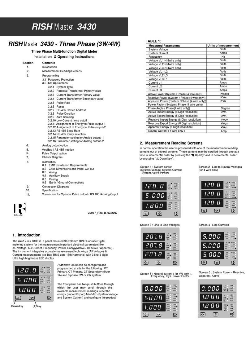
Rish Clamp ES1000AC User manual

Digital Clamp meters
RISH Clamp ES1000AC / ES400AC
User Manual
MULTIMETERMULTIMETER
FUNC AUTO
MAN
DATA
MIN/MAX
ON
OFF
FUNC AUTO
MAN
DATA
MIN/MAX
ON
OFF
RSHABH INSTRUMENTS
REL
OFF
NCV
/%


1
34567
8
2
1
(4)
Multimeter
FUNC AUTO
MAN
DATA
MIN/MAX
ON
OFF
MULTIMETER
FUNC AUTO
MAN
DATA
MIN/MAX
ON
OFF
MULTIMETER
REL
OFF
NCV
/%
(1)
(2) (3)
(5)
(6)
(7)
(10)
(9) (8)

Clamp meter Operating Elements
LCD Display
2
HOLD Pushbutton
8
9 Rotary mechanism for clamp jaws
Terminal Sockets
Limit for safe access for hand held
10 Safe trigger mechanism

3
1. Safety Features and Precautions ...................
2. Initial Start-up ...................................................
3. Selecting Measuring Functions & Ranges ....
3.1 Measuring Function Selection............................
3.2 Automatic Measuring Range Selection..............
3.3 Manual Measuring Range Selection..................
4. Liquid Crystal Display ....................................
4.1 Digital Display ...................................................
4.2 Display with Backlit .............................
5.0 Buzzer ..............................................................
6.0 Measurement Value Storage “ HOLD“............
7.0 REL - Relative value measurement ...............
8.0 Voltage Measurement .....................................
9.0 Current Measurement ....................................
4
6
7
7
8
8
9
9
9
10
10
10
11
12
10.0 Diode Testing & Continuity Measurement ....
10.1 Diode Testing ....................................................
10.2 Continuity Testing .............................................
11.0 Resistance Measurement ...............................
12.0 Capacitance Measurement ............................
13.0 Frequency & Duty cycle Measurement ........
13.1 Frequency Measurement .................................
13.2 Duty Cycle Measurement .................................
14.0 Temperature Measurement ............................
16.0 Specifications .................................................
17.0 Maintenance ....................................................
17.1 Battery ..............................................................
17.2 Housing .............................................................
18.0 Repair and Replacement parts service .........
15
15
16
16
17
19
19
19
20
21
26
26
27
27
15.0 Non contact voltage (NCV) detection.............. 20

1000 V
4
digital clamp meter
clamp meter

16
Meaning of the symbols
CAT II / III / IV
Warning of a danger point
(Attention, refer to the user manual)
Earth (ground) terminal.
Double or reinforced insulation
Instrument for over voltage
category II / III or IV
EU conformity mark.
5

6
17.1

white or yellow print
white half circle is reactivated .
color
7
17
battery compartment.
the battery cover
follow the instructions
described in
Press the HOLD key.
Switching the Meter ON again

AC
8
/%
This clamp meter

Note : 0
For Temperature ( C ), Frequency (Hz), Duty cycle (%)
and Capacitance (F) measuring range is always Auto.
No manual range selection is possible.
The digital display is updated thrice per sec-
4.2 Display with Backlight
By pressing
made ON. Back light will automatically switched off after 60 secs
9
ond for V, A, ,Cap Freq and duty cycle measurements.
Clamp 1000 A
Clamp 400 A
keys simultaneously back light can be
OR user can switch it off by pressing
REL
&
& yellow key
simultaneously.

AUTO/MAN key is activated
When measuring AC Voltage > 750 V, DC Voltage > 1000 V,
ACA > 400.0 A / ACA > 1000 A, the buzzer will
keep sounding as the overload warning.
Approximate 1 minute before the meter is auto power off,
the buzzer will raise constantly 5 sounds to warning.
Before the meter is power off, the buzzer will raise one long
sound to warn the user.
,Hz\%.
10
Hz

11
DC

Figure c
AUTO
AC
A
AUTO/MAN HOLD REL
0C
12
Clamp meter 1000A can measure current upto 1000 A, in two ranges
i.e. 400.0A and 1000 A. Where as Clamp meter 400A can measure
To measure the current through a cable, push the trigger(10) to open
One of the two ranges can be selected manually with AUTO/MAN key.
the jaws and clamp the jaws around the cable as shown in
figure a and figure b.
current up to 400 A in two ranges i.e. 40.00A and 400.0 A.
AUTO
AC
A
AUTO/MAN
HOLD
REL
0C
0C
Figure a Figure b
AC
A
AUTO/MAN HOLD REL
0C
Unique design for safety and comfort
Rotary mechanism for clamp jaws:
In conventional clamp meters display, keys and clamp jaws are in the same
plane. When current measurement is to be done on vertical bus bars, over head
cables, cables in congested places user connect the clamp meter but the keys
and display may not be visible, hence not able to take the readings or operate
the keys.
For accurate readings keep the conductor at center position of the jaws as shown in figure c
OFF
Hz/%
0C
OFF
Hz/%
0C
OFF
Hz/%

13
REL
AUTO/MAN
HOLD
AC
A
AUTO
0C
R Y B
90 º
AUTO AC
A
AUTO/MAN
HOLD
AUTO AC
A
AUTO/MAN
HOLD
AUTO AC
A
AUTO/MAN
HOLD
AUTO AC
A
AUTO/MAN
HOLD
REL
90 º
0C
0C
0C
0C
Figure d
Figure e
Normally, it is difficult to access the middle busbar for current measurement.
With ‘Rotary mechanism for clamp jaws’ it is easy to access middle bus bar,
while keeping display and keys facing towards the user as shown in figure e
on previous page.
To over come the above mentioned problem Clamp meter 400A/1000A has a
unique feature called ‘‘Rotary mechanism for clamp jaws’. In this, the clamp jaws
are rotating. Hence it is possible to align the clamp jaws as the orientation of
bus bar/conductor while keeping Display and keys facing the user, so that user can
take the readings and operate the keys.
Rotary clamp jaws can be rotated at different angles with the step of 30 maximumº,
up to 90 in both clock-wise as well as anti-clock wise direction as shown in figure d.º
0C
OFF
Hz/%
0C
OFF
Hz/%

Figure f:
55 mm
User’s hand is at safer distance from bare bus bar/conductor.
14
Safe trigger mechanism
The conventional clamp meters have trigger mechanism either near to
left jaw or right jaw. While taking measurements on bare bus bar or bare
conductor the user’s hand comes very close to bare bus bar/conductor,
which increases the risk of electric shocks to the user.
Also in conventional clamp meters trigger is operated with single finger,
usually a thumb which causes fatigue to the user while opening or closing
the clamp jaws.
To over come the above mentioned problems, Clamp meter 400A/1000A
has a unique feature called ‘Safe trigger mechanism’ in which trigger is
located at bottom side of the clamp meter and far away from the jaws
and hence the bus bar.
So user’s hand is at safer distance from bare conductors, hence minimizes
the risk of electric shock to the user. This is shown in figure f.
Also trigger can be comfortably operated with more than one finger which
eliminates fatigue to the user.

15
‘‘OL”
10 Diode Testing & Continuity Measurement
10.1 Diode Testing

11 Resistance Measurement
16
10.2 Continuity Testing

Deleting Zero Adjustment
Short the leads connected to meter and then press REL key.
or Activate the function selector switch.
or Switch the Clamp meter off.
17

18
Clearing Zero adjustment
or Switch the Clamp meter off.
This manual suits for next models
1
Table of contents
Other Rish Measuring Instrument manuals