Rish Master 3430 Manual

Screen12:MinSysVoltage&Current
2. Measurement Reading Screens
Innormaloperationtheuserispresentedwithoneofthemeasurementreading
screensoutofseveralscreens.Thesescreensmaybescrolledthroughoneata
timeinincrementalorderbypressingthe“Upkey”andindecrementalorder
bypressing“Downkey”.
Screen2:LinetoNeutralVoltages
(for4wireonly)
Screen1:Systemscreen
(SystemVoltage,SystemCurrent,
SystemActivePower)
Screen3:LinetoLineVoltages Screen4:LineCurrents
Screen6:SystemPower(Reactive,
VRY
KVAr
Sys
V
A
VYB
KVA
Min
KW
VBR
Angle
Max
x1000
KVArh
x1000
x1000
IN
PhR
Hz
KVAh
PhY
P.F.
KWh
PhB
VRY
KVAr
Sys
V
A
VYB
KVA
Min
KW
VBR
Angle
Max
x1000
x1000
x1000
IN
PhR
Hz
KVAh
PhY
P.F.
KWh
PhB
VRY
KVAr
Sys
V
A
VYB
KVA
Min
KW
VBR
Angle
Max
x1000
x1000
x1000
IN
PhR
Hz
KVAh
PhY
P.F.
KWh
PhB
VRY
KVAr
Sys
V
A
VYB
KVA
Min
KW
VBR
Angle
Max
x1000
x1000
x1000
IN
PhR
Hz
KVAh
PhY
P.F.
KWh
PhB
VRY
KVAr
Sys
V
A
VYB
KVA
Min
KW
VBR
Angle
Max
x1000
x1000
x1000
IN
PhR
Hz
KVAh
PhY
P.F.
KWh
PhB
VRY
KVAr
Sys
V
A
VYB
KVA
Min
KW
VBR
Angle
Max
x1000
x1000
x1000
IN
PhR
Hz
KVAh
PhY
P.F.
KWh
PhB
VRY
KVAr
Sys
V
A
VYB
KVA
Min
KW
VBR
Angle
Max
x1000
x1000
x1000
IN
PhR
Hz
KVAh
PhY
P.F.
KWh
PhB
VRY
KVAr
Sys
V
A
VYB
KVA
Min
KW
VBR
Angle
Max
x1000
x1000
x1000
IN
PhR
Hz
KVAh
PhY
P.F.
KWh
PhB
Apparent,Active)
MeasuredParameters
SystemVoltage
SystemCurrent
Frequency
VoltageVL1-N(4wireonly)
VoltageVL2-N(4wireonly)
VoltageVL3-N(4wireonly)
VoltageVL1-L2
VoltageVL2-L3
VoltageVL3-L1
CurrentL1
CurrentL2
CurrentL3
ActiveImportEnergy(8Digitresolution)
Unitsofmeasurement
Volts
Amps
Hz
Volts
Volts
Volts
Volts
Volts
Volts
Amps
Amps
Amps
kWh
TABLE1:
kWh
RISHABH 30987_Rev.B/03/2007
RISH3430-ThreePhase(3W/4W)Master
ThreePhaseMulti-functionDigitalMeter
Installation &OperatingInstructions
Section Contents
RISH3430Master
1. Introduction
2. MeasurementReadingScreens
3. Programming
3.1 PasswordProtection
3.2 SetUpScreens
3.2.1SystemType
3.2.2PotentialTransformerPrimaryvalue
3.2.3CurrentTransformerPrimaryvalue
3.2.4CurrentTransformerSecondaryvalue
3.2.5PulseRate
3.2.6Reset
3.2.7RS485DeviceAddress
3.2.8PulseDuration
3.2.9AutoScrolling
3.2.10LowCurrentnoisecutoff
3.2.11AssignmentofEnergytoPulseoutput-1
3.2.12AssignmentofEnergytoPulseoutput-2
3.2.13RS485BaudRate
3.2.14RS485Parityselection
3.2.15ParametersettingforAnalogoutput-1
3.2.16ParametersettingforAnalogoutput-2
10. Specification
8. Installation
8.1 EMCInstallationRequirements
8.2 CaseDimensionsandPanelCut-out
8.3 Wiring
8.4AuxiliarySupply
8.5Fusing
8.6Earth/GroundConnections
9. ConnectionDiagrams
11. ConnectionforOptionalPulseoutput/RS485/AnalogOuput
4. Analogoutputoption
ModBus(RS485)option
5.
1.Introduction
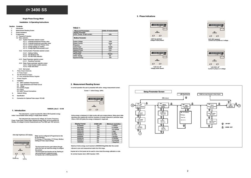
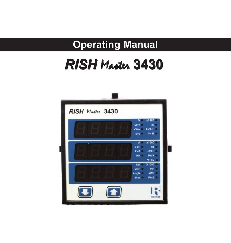
The3430isapanelmounted96x96mmDINQuadraticDigitalRish Master
meteringsystemforthemeasurementimportantelectricalparameterslike
ACVoltage,ACCurrent,Frequency,Power,Energy(Active/Reactive/Apparent).
Theinstrumentintegratesaccuratemeasurementtechnology(AllVoltages&
CurrentmeasurementsareTrueRMSupto15thHarmonic)with3line4digits
UltrahighbrightnessLEDdisplay.
Rish Master 3430canbeconfiguredand
programmedatsiteforthefollowing:PT
Primary,CTPrimary,CTSecondary(5Aor
1A)and3phase3Wor4Wsystem.
Thefrontpanelhastwopushbuttonsthrough
which the user may scroll through the
availablemeasurementreadings,resetthe
energy(Import/Export)Min/Max(SystemVoltage
andSystemCurrent) andconfiguretheproduct.
VRY
KVAr
Sys
V
A
VYB
KVA
Min
KW
VBR
Angle
Max
x1000
KVAr
x1000
x1000
Down Up
IN
PhR
Hz
KVAh
PhY
P.F.
KWh
PhB
ActiveExportEnergy(8Digitresolution)
ActivePower(System/Phase(4wireonly))
ReactivePower(System/Phase)(4wireonly)
ApparentPower(System/Phase)(4wireonly)
PowerFactor(System/Phase)(4wireonly)
PhaseAngle(Phase)(4wireonly)
Kwatts
KVAr
KVA
Degree
Screen5:Neutralcurrent(for4Wonly),
Sys.PowerFactorFrequency,
Screen:ActiveEnergy(Import)7Screen8:ActiveEnergy(Export)
VRY
KVAr
Sys
V
A
VYB
KVA
Min
KW
VBR
Angle
Max
x1000
x1000
x1000
IN
PhR
Hz
KVAh
PhY
P.F.
KWh
PhB
Screen9:ReactiveEnergy(Import)
VRY
KVAr
Sys
V
A
VYB
KVA
Min
KW
VBR
Angle
Max
x1000
KVArh
x1000
x1000
IN
PhR
Hz
KVAh
PhY
P.F.
KWh
PhB
Screen10:ReactiveEnergy(Export)
VRY
KVAr
Sys
V
A
VYB
KVA
Min
KW
VBR
Angle
Max
x1000
KVArh
x1000
x1000
IN
PhR
Hz
KVAh
PhY
P.F.
KWh
PhB
Screen11:ApparentEnergy
VRY
KVAr
Sys
V
A
VYB
KVA
Min
KW
VBR
Angle
Max
x1000
KVArh
x1000
x1000
IN
PhR
Hz
KVAh
PhY
P.F.
KWh
PhB
VRY
KVAr
Sys
V
A
VYB
KVA
Min
KW
VBR
Angle
Max
x1000
x1000
x1000
IN
PhR
Hz
KVAh
PhY
P.F.
KWh
PhB
VRY
KVAr
Sys
V
A
VYB
KVA
Min
KW
VBR
Angle
Max
x1000
KVArh
x1000
x1000
IN
PhR
Hz
KVAh
PhY
P.F.
KWh
PhB
VRY
KVAr
Sys
V
A
VYB
KVA
Min
KW
VBR
Angle
Max
x1000
x1000
x1000
IN
PhR
Hz
KVAh
PhY
P.F.
KWh
PhB
Screen14:PhasePower(R)
VRY
KVAr
Sys
V
A
VYB
KVA
Min
KW
VBR
Angle
Max
x1000
KVArh
x1000
x1000
IN
PhR
Hz
KVAh
PhY
P.F.
KWh
PhB
Reactive/Apparent/Active
Screen15:PhasePower(Y)
VRY
KVAr
Sys
V
A
VYB
KVA
Min
KW
VBR
Angle
Max
x1000
KVArh
x1000
x1000
IN
PhR
Hz
KVAh
PhY
P.F.
KWh
PhB
Reactive/Apparent/Active Screen16:PhasePower(B)
VRY
KVAr
Sys
V
A
VYB
KVA
Min
KW
VBR
Angle
Max
x1000
KVArh
x1000
x1000
IN
PhR
Hz
KVAh
PhY
P.F.
KWh
PhB
Reactive/Apparent/Active
Screen17:PhaseAngle
VRY
KVAr
Sys
V
A
VYB
KVA
Min
KW
VBR
Angle
Max
x1000
KVArh
x1000
x1000
IN
PhR
Hz
KVAh
PhY
P.F.
KWh
PhB
(PhaseR/Y/B) Screen18:PhasePowerFactor
VRY
KVAr
Sys
V
A
VYB
KVA
Min
KW
VBR
Angle
Max
x1000
KVArh
x1000
x1000
IN
PhR
Hz
KVAh
PhY
P.F.
KWh
PhB
(PhaseR/Y/B)
Screen13:MaxSysVoltage
&Current
EnterPassword,firstdigitentered,promptforsecond
digit.
(*Denotesthatdecimalpointwillbeflashing).
Usethe“Down”keytoscrollthevalueofthesecond
digitfrom0throughto9,thevaluewillwrapfrom9
roundto0.
Pressthe“Up”keytoadvancetonextdigit.
3.Programming
Thefollowingsectionscomprisestepbystepproceduresforconfiguringthe
Rish3430Master forindividualuserrequirements.
Toaccesstheset-upscreenspressandholdthe“
Keysimultaneouslyfor5seconds.ThiswilltaketheUserintothePassword
ProtectionEntryStage(Section3.1).
3.1.PasswordProtection
Passwordprotectioncanbeenabledtopreventunauthorisedaccesstoset-up
screens,bydefaultpasswordprotectionisnotenabled.
Passwordprotectionisenabledbyselectingafourdigitnumberotherthan0000,
settingapasswordof0000disablesthepasswordprotection.
Down”and“Up”
EnterPassword,promptforfirstdigit.
(*Denotesthatdecimalpointwillbeflashing).
Pressthe“Down”keytoscrollthevalueofthefirstdigit
from0throughto9,thevaluewillwrapfrom9roundto0.
Pressthe“Up”keytoadvancetonextdigit.
InthespecialcasewherethePasswordis“0000”pressing
the“Up”keywhenpromptedforthefirstdigitwill
advancetothe“PasswordConfirmed”screen.
VRY
KVAr
Sys
V
A
VYB
KVA
Min
KW
VBR
Angle
Max
x1000
KVArh
x1000
x1000
IN
PhR
Hz
KVAh
PhY
P.F.
KWh
PhB
VRY
KVAr
Sys
V
A
VYB
KVA
Min
KW
VBR
Angle
Max
x1000
KVArh
x1000
x1000
IN
PhR
Hz
KVAh
PhY
P.F.
KWh
PhB
EnterPassword,seconddigitentered,promptforthird
digit.
(*Denotesthatdecimalpointwillbeflashing).
Usethe“Down”keytoscrollthevalueofthethird
digitfrom0throughto9,thevaluewillwrapfrom9
roundto0.
Pressthe“Up”keytoadvancetonextdigit.
EnterPassword,thirddigitentered,promptforfourth
digit.
(*Denotesthatdecimalpointwillbeflashing).
Usethe“Down”keytoscrollthevalueofthefourth
digitfrom0throughto9,thevaluewillwrapfrom9
roundto0.
Pressthe“Up”keytoadvancetoverificationofthe
password.
EnterPassword,fourthdigitentered,awaiting
verificationofthepassword.
Passwordconfirmed.
Pressing“Down”keywilladvancetothe“New/
changePassword”entrystage.
Pressingthe“Up”keywilladvancetotheSetup
screen.(Seesection3.2).
VRY
KVAr
Sys
V
A
VYB
KVA
Min
KW
VBR
Angle
Max
x1000
KVArh
x1000
x1000
IN
PhR
Hz
KVAh
PhY
P.F.
KWh
PhB
VRY
KVAr
Sys
V
A
VYB
KVA
Min
KW
VBR
Angle
Max
x1000
KVArh
x1000
x1000
IN
PhR
Hz
KVAh
PhY
P.F.
KWh
PhB
VRY
KVAr
Sys
V
A
VYB
KVA
Min
KW
VBR
Angle
Max
x1000
KVArh
x1000
x1000
IN
PhR
Hz
KVAh
PhY
P.F.
KWh
PhB
VRY
KVAr
Sys
V
A
VYB
KVA
Min
KW
VBR
Angle
Max
x1000
KVArh
x1000
x1000
IN
PhR
Hz
KVAh
PhY
P.F.
KWh
PhB
PulseOutputoption
7.
kVArh
ReactiveImportEnergy(8Digitresolution) kVArh
ReactiveExportEnergy(8Digitresolution) kVAh
ApparentEnergy(8Digitresolution)
(for4Wonly)
(for4Wonly) (for4Wonly)
PhaserDiagram
6.
KVArh
KVArh
KVArh
KVArh
KVArh KVArh
KVArh
KVArh
KVArh
Amp
NeutralCurrent(4wireonly)

CTSecondaryvalueconfirmation
ThisscreenwillonlyappearsfollowinganeditofCT
secondaryvalue.
Ifsecondaryvalueshownisnotcorrect,pressingthe
DownkeywillreturntoCTsecondaryeditstageby
blankingthebottomlineofthedisplay.
Pressing“Up”keysetsthedisplayedvalueand
willadvancetoPulseRateEditmenu.
(Seesection3.2.5)
3.2.5.PulseRate
ThisscreenappliestotheRelayOutputoptiononly.Thescreenallowsusertosettheenergy
pulseratedivisor.Divisorvaluescanbeselectedthrough1,10,100,1000.
Pressing“Up”keyacceptsthepresentsvalue
andadvancestothe“Reset”menu
(Seesection3.2.6).
Pressingthe“Down”keywillenterthe“Pulseratedivisor
Edit”modeandscrollthevaluethroughthevalues1,10,100,
1000wrappingbackto1.
Pressingthe“Up”keyadvancestothe“Pulserate
Divisor Confirmation”menu.
PulseRateDivisorConfirmation.
Thisscreenwillonlyappearfollowinganeditofthe
Pulseratedivisor.
IfthePulserateshownisnotcorrect,pressingthe“
Down”keywillreturntothe“Pulseratedivisor
Edit”stagebyblankingthebottomlineofthe
display.
Pressing“Up”keysetsthedisplayedvalueand
willadvancetothe“Reset”menu.
(See section3.2.6)
PasswordIncorrect.
Theunithasnotacceptedthe
Passwordentered.
Pressingthe" Down"keywillreturnto
theEnterPasswordstage.
Pressingthe“Up”keyexitsthe
Passwordmenuandreturnsoperation
tothemeasurementreadingmode.
New/ChangePassword
(*Decimalpointindicatesthatthiswillbeflashing).
Pressingthe“Down”keywillscrollthevalueofthe
firstdigitfrom0throughto9,thevaluewillwrapfrom9
roundto0.
Pressingthe“Up”keytoadvancetheoperationto
thenextdigitandsetsthefirstdigit,inthiscaseto“2”
New/ChangePassword,firstdigitentered,promptingfor
seconddigit.(*Decimalpointindicatesthatthiswillbe
flashing).
Pressingthe“Down”keywillscrollthevalueofthe
seconddigitfrom0throughto9,thevaluewillwrapfrom
9roundto0.
Pressingthe“Up”keytoadvancetheoperationtothe
nextdigitandsetstheseconddigit,inthiscaseto“1”
New/ChangePassword,thirddigitentered,prompting
forfourthdigit.(*denotesthatdecimalpointwillbe
flashing).
Pressingthe“Down”keywillscrollthevalueofthe
fourthdigitfrom0throughto9,thevaluewillwrapfrom
9roundto0.
Pressingthe“Up”keytoadvancetheoperationto
the“NewPasswordConfirmed”andsetsthefourthdigit,
inthiscaseto“3”.
NewPasswordconfirmed.
Pressingthe“Down”keywillreturntothe
“New/ChangePassword”.
Pressingthe“Up”keywilladvancestotheSetup
screen.(seesection3.2).
New/ChangePassword,seconddigitentered,
promptingforthirddigit.(*decimalpointindicatesthat
thiswillbeflashing).
Pressingthe“Down”keywillscrollthevalueofthe
thirddigitfrom0throughto9,thevaluewillwrapfrom9
roundto0.
Pressingthe“Up”keytoadvancetheoperationto
thenextdigitandsetsthethirddigit,inthiscaseto“5”
3.2.1.SystemType
3.2SetUpScreens
Thisscreenisusedtosetthesystemtype.
Systemtype”3”for3phase3wire&“4”for3phase
4wiresystem.
Pressingthe“Up”keyacceptsthepresentvalueandadvancestothe“Potentialtransformer
primaryvalueEdit”menu(seesection3.2.2)
Pressingthe“Down”keywillenterthesystemtypeeditmodeandscrollthevaluesthroughvalues
available.
Pressingthe“Up”keyadvancestothesystemtypeconfirmationmenu.
Thisscreenwillonlyappearfollowingtheeditof
systemtype.IfsystemtypeistobeDownedagain,
pressingthe“Down”keywillreturntothesystemtype
editstagebyblankingthebottomlineofthedisplay
pressingthe“Up”keysetsthedisplayedvalueand
willadvanceto“PotentialTransformerPrimaryValue
Edit”menu.(Seesection3.2.2)
SystemTypeConfirmation
VRY
KVAr
Sys
V
A
VYB
KVA
Min
KW
VBR
Angle
Max
x1000
KVArh
x1000
x1000
IN
PhR
Hz
KVAh
PhY
P.F.
KWh
PhB
VRY
KVAr
Sys
V
A
VYB
KVA
Min
KW
VBR
Angle
Max
x1000
KVArh
x1000
x1000
IN
PhR
Hz
KVAh
PhY
P.F.
KWh
PhB
PotentialTransformerDigitEdit
Pressingthe“Down”keywillscrollthevalueof
themostsignificantdigitfrom0throughto9unless
thepresentlydisplayedPotentialTransformerPrimary
ValuetogetherwiththeCurrentTransformerPrimary
Value,previously set,wouldresultinamaximumpower
ofgreaterthan 1000MVAinwhichcasethedigitrange
willbe restricted.
Pressingthe“Up”keyacceptsthepresentvalue
atthecursorpositionandadvancesthecursortothe
nextlesssignificantdigit.
3.2.2.PotentialTransformer PrimaryValue
ThenominalfullscalevoltagewhichwillbedisplayedastheL1-N,L2-NandL3-Nforafourwire(Ln)
systemorasL1-2,L2-3andL3-1inathreewire(LL)system.Thisscreenenablestheusertodisplay
thelinetoneutralandlinetolinevoltagesinclusiveofanytransformerratios,thevaluesdisplayed
representthevoltageinkilovolts(notethex1000enunciator).
Pressingthe“Up”keyacceptsthepresentvalue
andadvancestothe“CurrentTransformerPrimary
Valueedit”menu.(SeeSection3.2.3)
Pressingthe“Down”keywillenterthe“Potential
TransformerPrimaryValueEdit”mode.
Initiallythe“multipliermustbeselected,pressingthe“
Down”keywillmovethedecimalpointpositiontothe
rightuntilitreaches###.#afterwhichitwillreturnto
#.###.
Pressingthe“Up”keyacceptsthepresent
multiplier(decimalpointposition)andadvancestothe
“PotentialTransformerDigitEdit”mode.
VRY
KVAr
Sys
V
A
VYB
KVA
Min
KW
VBR
Angle
Max
x1000
KVArh
x1000
x1000
IN
PhR
Hz
KVAh
PhY
P.F.
KWh
PhB
VRY
KVAr
Sys
V
A
VYB
KVA
Min
KW
VBR
Angle
Max
x1000
KVArh
x1000
x1000
IN
PhR
Hz
KVAh
PhY
P.F.
KWh
PhB
restricted,thevaluewillwrap.Example:Ifprimaryvalue
ofPTissetas400kV(maxvalue)thenprimaryvalueof
Currentisrestrictedto1736A.
Pressingthe“Up”keywilladvancetothenextless
significantdigit.(*Denotesthatdecimalpointwillbe
flashing).
Note:theflashingdecimalpointindicatesthecursorposition,asteadydecimalpointwillbepresent
toidentifythescalingofthenumberuntilthecursorpositioncoincideswiththesteadydecimalpoint
position.Atthisstagethedecimalpointwillflash.
Whentheleastsignificantdigithasbeensetpressingthe“Up”keywilladvancetothe
“PotentialTransformerPrimaryValueConfirmation”stage.
Screenshowingdisplayof0.120kVi.e.120Voltsindicatingsteadydecimalpointandcursor
flashingatthe“hundredsofvolts”position.
PotentialTransformerPrimaryValueConfirmation
Thisscreenwillonlyappearfollowinganeditofthe
PotentialTransformerPrimaryValue.
Ifthescalingisnotcorrect,pressingthe“Down”
keywillreturntothe“PotentialTransformerPrimary
ValueEdit”stagewiththedigitsflashingindicating
thatthemultiplier(decimalpointposition)shouldbe
selected.
Pressingthe“Up”keysetsthedisplayedvalue
andwilladvancetotheCurrentTransformerPrimary
Value(Seesection3.2.3.)
Note:0.120kVi.e.120V for4W
L-N
120V fpr3W
L-L
3.2.3.CurrentPrimaryValueTransformer
ThenominalFullScaleCurrentthatwillbedisplayedastheLinecurrents.Thisscreenenablesthe
usertodisplaytheLinecurrentsinclusiveofanytransformerratios,thevaluesdisplayedrepresent
theCurrentinAmps.
Pressingthe“Up”keyacceptsthepresentvalueandadvancestotheCurrentTransformer
SecondaryValue(Seesection3.2.4)
Pressingthe“Down”keywillenterthe“Current
TransformerPrimaryValueEdit”mode.Thiswillscrollthe
valueofthemostsignificantdigitfrom0throughto9,
unlessthepresentlydisplayedCurrentTransformer
PrimaryValuetogetherwiththePotentialTransformer
PrimaryValueresultsinamaximumpowerofgreater
than1000MVAinwhichcasethedigitrangewillbe
VRY
KVAr
Sys
V
A
VYB
KVA
Min
KW
VBR
Angle
Max
x1000
KVArh
x1000
x1000
IN
PhR
Hz
KVAh
PhY
P.F.
KWh
PhB
VRY
KVAr
Sys
V
A
VYB
KVA
Min
KW
VBR
Angle
Max
x1000
KVArh
x1000
x1000
IN
PhR
Hz
KVAh
PhY
P.F.
KWh
PhB
The“MaximumPower”restrictionof1000MVArefersto120%ofnominalcurrentand120%of
nominalvoltage,i.e,694.4MVAnominalsystempower.
Whentheleastsignificantdigithadbeenset,pressingthe“Up”keywilladvancetothe
“CurrentTransformerPrimaryValueConfirmation”stage.
Theminimumvalueallowedis1,thevaluewillbeforcedto1ifthedisplaycontainszerowhenthe
“Up”keyispressed.
CurrentTransformerPrimaryValueConfirmation.
Thisscreenwillonlyappearfollowinganeditofthe
.
Ifthescalingisnotcorrect,Pressingthe“Down”key
willreturntothe“ Edit
stagewiththemostsignificantdigithighlighted(associated
decimalpointflashing)andthebottomlineofthedisplay
willbeblanked.
Pressingthe“Up”keysetsthedisplayedvalueand
willadvancetothe“CurrentTransformerSecondaryValue
Edit”menu.(Seesection3.2.4).
Current
TransformerPrimaryValue
CurrentTransformerPrimaryValue ”
3.2.4.CurrentTransformerSecondaryValue
Thisscreenisusedtosetthesecondaryvaluefor
CurrentTransformer.Secondaryvalue“5”for5Aor
“1”for1Acanbeselected.Pressing“Up”key
acceptsthepresentvalueandadvancestothe
PulseRateeditmenu(Seesection
3.2.5).
Pressingthe“Down”keywillentertheCT
Secondaryvalueeditmodeandscrollthevalue
throughthevaluesavailable.
Pressingthe“Up”keywilladvancetotheCT
Secondaryvalueconfirmation.
3.2.6.Resets
ThefollowingscreensallowtheuserstoresettheallEnergy,Lo(Min),hi(Max).
Reset(None)
Pressing“Up”keywillnotresetandwilladvance
toPulseDurationmenu.(Seesec.3.2.7)
Pressingthe“Down”keywillenterthe“Reset
option”modeandscrollthevalue”
throughtheoptionandwrappingbacktoNone.
Pressing“Up”keyadvancestoPulseDurationmenu.
(seesection3.2.7).
Resetoptionselect,(ResetEnergy)
Theuserhasscrolledthroughtothe“E”Energy
value.
Pressing“Up”keywillselectthevalueand
advancetothe“ResetEnergyConfirmation”Mode.
VRY
KVAr
Sys
V
A
VYB
KVA
Min
KW
VBR
Angle
Max
x1000
KVArh
x1000
x1000
IN
PhR
Hz
KVAh
PhY
P.F.
KWh
PhB
VRY
KVAr
Sys
V
A
VYB
KVA
Min
KW
VBR
Angle
Max
x1000
KVArh
x1000
x1000
IN
PhR
Hz
KVAh
PhY
P.F.
KWh
PhB
VRY
KVAr
Sys
V
A
VYB
KVA
Min
KW
VBR
Angle
Max
x1000
KVArh
x1000
x1000
IN
PhR
Hz
KVAh
PhY
P.F.
KWh
PhB
VRY
KVAr
Sys
V
A
VYB
KVA
Min
KW
VBR
Angle
Max
x1000
KVArh
x1000
x1000
IN
PhR
Hz
KVAh
PhY
P.F.
KWh
PhB
VRY
KVAr
Sys
V
A
VYB
KVA
Min
KW
VBR
Angle
Max
x1000
KVArh
x1000
x1000
IN
PhR
Hz
KVAh
PhY
P.F.
KWh
PhB
VRY
KVAr
Sys
V
A
VYB
KVA
Min
KW
VBR
Angle
Max
x1000
KVArh
x1000
x1000
IN
PhR
Hz
KVAh
PhY
P.F.
KWh
PhB
VRY
KVAr
Sys
V
A
VYB
KVA
Min
KW
VBR
Angle
Max
x1000
KVArh
x1000
x1000
IN
PhR
Hz
KVAh
PhY
P.F.
KWh
PhB
VRY
KVAr
Sys
V
A
VYB
KVA
Min
KW
VBR
Angle
Max
x1000
KVArh
x1000
x1000
IN
PhR
Hz
KVAh
PhY
P.F.
KWh
PhB
VRY
KVAr
Sys
V
A
VYB
KVA
Min
KW
VBR
Angle
Max
x1000
KVArh
x1000
x1000
IN
PhR
Hz
KVAh
PhY
P.F.
KWh
PhB
VRY
KVAr
Sys
V
A
VYB
KVA
Min
KW
VBR
Angle
Max
x1000
KVArh
x1000
x1000
IN
PhR
Hz
KVAh
PhY
P.F.
KWh
PhB
VRY
KVAr
Sys
V
A
VYB
KVA
Min
KW
VBR
Angle
Max
x1000
KVArh
x1000
x1000
IN
PhR
Hz
KVAh
PhY
P.F.
KWh
PhB
VRY
KVAr
Sys
V
A
VYB
KVA
Min
KW
VBR
Angle
Max
x1000
KVArh
x1000
x1000
IN
PhR
Hz
KVAh
PhY
P.F.
KWh
PhB
VRY
KVAr
Sys
V
A
VYB
KVA
Min
KW
VBR
Angle
Max
x1000
KVArh
x1000
x1000
IN
PhR
Hz
KVAh
PhY
P.F.
KWh
PhB
ResetEnergyConfirmation.
Pressing“Up”keyresetstheallEnergyparameters
andadvancestothePulseDuration
(seesection3.2.7.)
Pressingthe“Down”keywillre-enterthe“Reset
option”mode.
VRY
KVAr
Sys
V
A
VYB
KVA
Min
KW
VBR
Angle
Max
x1000
KVArh
x1000
x1000
IN
PhR
Hz
KVAh
PhY
P.F.
KWh
PhB
Resetoptionselect,(ResetLo)
Theuserhasscrolledthroughtothe“Lo”(Min)
Pressing“Up”keywillselectthevalueand
advancetothe“ResetLoConfirmation”Mode.
VRY
KVAr
Sys
V
A
VYB
KVA
Min
KW
VBR
Angle
Max
x1000
KVArh
x1000
x1000
IN
PhR
Hz
KVAh
PhY
P.F.
KWh
PhB

CTSecondaryvalueconfirmation
ThisscreenwillonlyappearsfollowinganeditofCT
secondaryvalue.
Ifsecondaryvalueshownisnotcorrect,pressingthe
DownkeywillreturntoCTsecondaryeditstageby
blankingthebottomlineofthedisplay.
Pressing“Up”keysetsthedisplayedvalueand
willadvancetoPulseRateEditmenu.
(Seesection3.2.5)
3.2.5.PulseRate
ThisscreenappliestotheRelayOutputoptiononly.Thescreenallowsusertosettheenergy
pulseratedivisor.Divisorvaluescanbeselectedthrough1,10,100,1000.
Pressing“Up”keyacceptsthepresentsvalue
andadvancestothe“Reset”menu
(Seesection3.2.6).
Pressingthe“Down”keywillenterthe“Pulseratedivisor
Edit”modeandscrollthevaluethroughthevalues1,10,100,
1000wrappingbackto1.
Pressingthe“Up”keyadvancestothe“Pulserate
Divisor Confirmation”menu.
PulseRateDivisorConfirmation.
Thisscreenwillonlyappearfollowinganeditofthe
Pulseratedivisor.
IfthePulserateshownisnotcorrect,pressingthe“
Down”keywillreturntothe“Pulseratedivisor
Edit”stagebyblankingthebottomlineofthe
display.
Pressing“Up”keysetsthedisplayedvalueand
willadvancetothe“Reset”menu.
(See section3.2.6)
PasswordIncorrect.
Theunithasnotacceptedthe
Passwordentered.
Pressingthe" Down"keywillreturnto
theEnterPasswordstage.
Pressingthe“Up”keyexitsthe
Passwordmenuandreturnsoperation
tothemeasurementreadingmode.
New/ChangePassword
(*Decimalpointindicatesthatthiswillbeflashing).
Pressingthe“Down”keywillscrollthevalueofthe
firstdigitfrom0throughto9,thevaluewillwrapfrom9
roundto0.
Pressingthe“Up”keytoadvancetheoperationto
thenextdigitandsetsthefirstdigit,inthiscaseto“2”
New/ChangePassword,firstdigitentered,promptingfor
seconddigit.(*Decimalpointindicatesthatthiswillbe
flashing).
Pressingthe“Down”keywillscrollthevalueofthe
seconddigitfrom0throughto9,thevaluewillwrapfrom
9roundto0.
Pressingthe“Up”keytoadvancetheoperationtothe
nextdigitandsetstheseconddigit,inthiscaseto“1”
New/ChangePassword,thirddigitentered,prompting
forfourthdigit.(*denotesthatdecimalpointwillbe
flashing).
Pressingthe“Down”keywillscrollthevalueofthe
fourthdigitfrom0throughto9,thevaluewillwrapfrom
9roundto0.
Pressingthe“Up”keytoadvancetheoperationto
the“NewPasswordConfirmed”andsetsthefourthdigit,
inthiscaseto“3”.
NewPasswordconfirmed.
Pressingthe“Down”keywillreturntothe
“New/ChangePassword”.
Pressingthe“Up”keywilladvancestotheSetup
screen.(seesection3.2).
New/ChangePassword,seconddigitentered,
promptingforthirddigit.(*decimalpointindicatesthat
thiswillbeflashing).
Pressingthe“Down”keywillscrollthevalueofthe
thirddigitfrom0throughto9,thevaluewillwrapfrom9
roundto0.
Pressingthe“Up”keytoadvancetheoperationto
thenextdigitandsetsthethirddigit,inthiscaseto“5”
3.2.1.SystemType
3.2SetUpScreens
Thisscreenisusedtosetthesystemtype.
Systemtype”3”for3phase3wire&“4”for3phase
4wiresystem.
Pressingthe“Up”keyacceptsthepresentvalueandadvancestothe“Potentialtransformer
primaryvalueEdit”menu(seesection3.2.2)
Pressingthe“Down”keywillenterthesystemtypeeditmodeandscrollthevaluesthroughvalues
available.
Pressingthe“Up”keyadvancestothesystemtypeconfirmationmenu.
Thisscreenwillonlyappearfollowingtheeditof
systemtype.IfsystemtypeistobeDownedagain,
pressingthe“Down”keywillreturntothesystemtype
editstagebyblankingthebottomlineofthedisplay
pressingthe“Up”keysetsthedisplayedvalueand
willadvanceto“PotentialTransformerPrimaryValue
Edit”menu.(Seesection3.2.2)
SystemTypeConfirmation
VRY
KVAr
Sys
V
A
VYB
KVA
Min
KW
VBR
Angle
Max
x1000
KVArh
x1000
x1000
IN
PhR
Hz
KVAh
PhY
P.F.
KWh
PhB
VRY
KVAr
Sys
V
A
VYB
KVA
Min
KW
VBR
Angle
Max
x1000
KVArh
x1000
x1000
IN
PhR
Hz
KVAh
PhY
P.F.
KWh
PhB
PotentialTransformerDigitEdit
Pressingthe“Down”keywillscrollthevalueof
themostsignificantdigitfrom0throughto9unless
thepresentlydisplayedPotentialTransformerPrimary
ValuetogetherwiththeCurrentTransformerPrimary
Value,previously set,wouldresultinamaximumpower
ofgreaterthan 1000MVAinwhichcasethedigitrange
willbe restricted.
Pressingthe“Up”keyacceptsthepresentvalue
atthecursorpositionandadvancesthecursortothe
nextlesssignificantdigit.
3.2.2.PotentialTransformer PrimaryValue
ThenominalfullscalevoltagewhichwillbedisplayedastheL1-N,L2-NandL3-Nforafourwire(Ln)
systemorasL1-2,L2-3andL3-1inathreewire(LL)system.Thisscreenenablestheusertodisplay
thelinetoneutralandlinetolinevoltagesinclusiveofanytransformerratios,thevaluesdisplayed
representthevoltageinkilovolts(notethex1000enunciator).
Pressingthe“Up”keyacceptsthepresentvalue
andadvancestothe“CurrentTransformerPrimary
Valueedit”menu.(SeeSection3.2.3)
Pressingthe“Down”keywillenterthe“Potential
TransformerPrimaryValueEdit”mode.
Initiallythe“multipliermustbeselected,pressingthe“
Down”keywillmovethedecimalpointpositiontothe
rightuntilitreaches###.#afterwhichitwillreturnto
#.###.
Pressingthe“Up”keyacceptsthepresent
multiplier(decimalpointposition)andadvancestothe
“PotentialTransformerDigitEdit”mode.
VRY
KVAr
Sys
V
A
VYB
KVA
Min
KW
VBR
Angle
Max
x1000
KVArh
x1000
x1000
IN
PhR
Hz
KVAh
PhY
P.F.
KWh
PhB
VRY
KVAr
Sys
V
A
VYB
KVA
Min
KW
VBR
Angle
Max
x1000
KVArh
x1000
x1000
IN
PhR
Hz
KVAh
PhY
P.F.
KWh
PhB
restricted,thevaluewillwrap.Example:Ifprimaryvalue
ofPTissetas400kV(maxvalue)thenprimaryvalueof
Currentisrestrictedto1736A.
Pressingthe“Up”keywilladvancetothenextless
significantdigit.(*Denotesthatdecimalpointwillbe
flashing).
Note:theflashingdecimalpointindicatesthecursorposition,asteadydecimalpointwillbepresent
toidentifythescalingofthenumberuntilthecursorpositioncoincideswiththesteadydecimalpoint
position.Atthisstagethedecimalpointwillflash.
Whentheleastsignificantdigithasbeensetpressingthe“Up”keywilladvancetothe
“PotentialTransformerPrimaryValueConfirmation”stage.
Screenshowingdisplayof0.120kVi.e.120Voltsindicatingsteadydecimalpointandcursor
flashingatthe“hundredsofvolts”position.
PotentialTransformerPrimaryValueConfirmation
Thisscreenwillonlyappearfollowinganeditofthe
PotentialTransformerPrimaryValue.
Ifthescalingisnotcorrect,pressingthe“Down”
keywillreturntothe“PotentialTransformerPrimary
ValueEdit”stagewiththedigitsflashingindicating
thatthemultiplier(decimalpointposition)shouldbe
selected.
Pressingthe“Up”keysetsthedisplayedvalue
andwilladvancetotheCurrentTransformerPrimary
Value(Seesection3.2.3.)
Note:0.120kVi.e.120V for4W
L-N
120V fpr3W
L-L
3.2.3.CurrentPrimaryValueTransformer
ThenominalFullScaleCurrentthatwillbedisplayedastheLinecurrents.Thisscreenenablesthe
usertodisplaytheLinecurrentsinclusiveofanytransformerratios,thevaluesdisplayedrepresent
theCurrentinAmps.
Pressingthe“Up”keyacceptsthepresentvalueandadvancestotheCurrentTransformer
SecondaryValue(Seesection3.2.4)
Pressingthe“Down”keywillenterthe“Current
TransformerPrimaryValueEdit”mode.Thiswillscrollthe
valueofthemostsignificantdigitfrom0throughto9,
unlessthepresentlydisplayedCurrentTransformer
PrimaryValuetogetherwiththePotentialTransformer
PrimaryValueresultsinamaximumpowerofgreater
than1000MVAinwhichcasethedigitrangewillbe
VRY
KVAr
Sys
V
A
VYB
KVA
Min
KW
VBR
Angle
Max
x1000
KVArh
x1000
x1000
IN
PhR
Hz
KVAh
PhY
P.F.
KWh
PhB
VRY
KVAr
Sys
V
A
VYB
KVA
Min
KW
VBR
Angle
Max
x1000
KVArh
x1000
x1000
IN
PhR
Hz
KVAh
PhY
P.F.
KWh
PhB
The“MaximumPower”restrictionof1000MVArefersto120%ofnominalcurrentand120%of
nominalvoltage,i.e,694.4MVAnominalsystempower.
Whentheleastsignificantdigithadbeenset,pressingthe“Up”keywilladvancetothe
“CurrentTransformerPrimaryValueConfirmation”stage.
Theminimumvalueallowedis1,thevaluewillbeforcedto1ifthedisplaycontainszerowhenthe
“Up”keyispressed.
CurrentTransformerPrimaryValueConfirmation.
Thisscreenwillonlyappearfollowinganeditofthe
.
Ifthescalingisnotcorrect,Pressingthe“Down”key
willreturntothe“ Edit
stagewiththemostsignificantdigithighlighted(associated
decimalpointflashing)andthebottomlineofthedisplay
willbeblanked.
Pressingthe“Up”keysetsthedisplayedvalueand
willadvancetothe“CurrentTransformerSecondaryValue
Edit”menu.(Seesection3.2.4).
Current
TransformerPrimaryValue
CurrentTransformerPrimaryValue ”
3.2.4.CurrentTransformerSecondaryValue
Thisscreenisusedtosetthesecondaryvaluefor
CurrentTransformer.Secondaryvalue“5”for5Aor
“1”for1Acanbeselected.Pressing“Up”key
acceptsthepresentvalueandadvancestothe
PulseRateeditmenu(Seesection
3.2.5).
Pressingthe“Down”keywillentertheCT
Secondaryvalueeditmodeandscrollthevalue
throughthevaluesavailable.
Pressingthe“Up”keywilladvancetotheCT
Secondaryvalueconfirmation.
3.2.6.Resets
ThefollowingscreensallowtheuserstoresettheallEnergy,Lo(Min),hi(Max).
Reset(None)
Pressing“Up”keywillnotresetandwilladvance
toPulseDurationmenu.(Seesec.3.2.7)
Pressingthe“Down”keywillenterthe“Reset
option”modeandscrollthevalue”
throughtheoptionandwrappingbacktoNone.
Pressing“Up”keyadvancestoPulseDurationmenu.
(seesection3.2.7).
Resetoptionselect,(ResetEnergy)
Theuserhasscrolledthroughtothe“E”Energy
value.
Pressing“Up”keywillselectthevalueand
advancetothe“ResetEnergyConfirmation”Mode.
VRY
KVAr
Sys
V
A
VYB
KVA
Min
KW
VBR
Angle
Max
x1000
KVArh
x1000
x1000
IN
PhR
Hz
KVAh
PhY
P.F.
KWh
PhB
VRY
KVAr
Sys
V
A
VYB
KVA
Min
KW
VBR
Angle
Max
x1000
KVArh
x1000
x1000
IN
PhR
Hz
KVAh
PhY
P.F.
KWh
PhB
VRY
KVAr
Sys
V
A
VYB
KVA
Min
KW
VBR
Angle
Max
x1000
KVArh
x1000
x1000
IN
PhR
Hz
KVAh
PhY
P.F.
KWh
PhB
VRY
KVAr
Sys
V
A
VYB
KVA
Min
KW
VBR
Angle
Max
x1000
KVArh
x1000
x1000
IN
PhR
Hz
KVAh
PhY
P.F.
KWh
PhB
VRY
KVAr
Sys
V
A
VYB
KVA
Min
KW
VBR
Angle
Max
x1000
KVArh
x1000
x1000
IN
PhR
Hz
KVAh
PhY
P.F.
KWh
PhB
VRY
KVAr
Sys
V
A
VYB
KVA
Min
KW
VBR
Angle
Max
x1000
KVArh
x1000
x1000
IN
PhR
Hz
KVAh
PhY
P.F.
KWh
PhB
VRY
KVAr
Sys
V
A
VYB
KVA
Min
KW
VBR
Angle
Max
x1000
KVArh
x1000
x1000
IN
PhR
Hz
KVAh
PhY
P.F.
KWh
PhB
VRY
KVAr
Sys
V
A
VYB
KVA
Min
KW
VBR
Angle
Max
x1000
KVArh
x1000
x1000
IN
PhR
Hz
KVAh
PhY
P.F.
KWh
PhB
VRY
KVAr
Sys
V
A
VYB
KVA
Min
KW
VBR
Angle
Max
x1000
KVArh
x1000
x1000
IN
PhR
Hz
KVAh
PhY
P.F.
KWh
PhB
VRY
KVAr
Sys
V
A
VYB
KVA
Min
KW
VBR
Angle
Max
x1000
KVArh
x1000
x1000
IN
PhR
Hz
KVAh
PhY
P.F.
KWh
PhB
VRY
KVAr
Sys
V
A
VYB
KVA
Min
KW
VBR
Angle
Max
x1000
KVArh
x1000
x1000
IN
PhR
Hz
KVAh
PhY
P.F.
KWh
PhB
VRY
KVAr
Sys
V
A
VYB
KVA
Min
KW
VBR
Angle
Max
x1000
KVArh
x1000
x1000
IN
PhR
Hz
KVAh
PhY
P.F.
KWh
PhB
VRY
KVAr
Sys
V
A
VYB
KVA
Min
KW
VBR
Angle
Max
x1000
KVArh
x1000
x1000
IN
PhR
Hz
KVAh
PhY
P.F.
KWh
PhB
ResetEnergyConfirmation.
Pressing“Up”keyresetstheallEnergyparameters
andadvancestothePulseDuration
(seesection3.2.7.)
Pressingthe“Down”keywillre-enterthe“Reset
option”mode.
VRY
KVAr
Sys
V
A
VYB
KVA
Min
KW
VBR
Angle
Max
x1000
KVArh
x1000
x1000
IN
PhR
Hz
KVAh
PhY
P.F.
KWh
PhB
Resetoptionselect,(ResetLo)
Theuserhasscrolledthroughtothe“Lo”(Min)
Pressing“Up”keywillselectthevalueand
advancetothe“ResetLoConfirmation”Mode.
VRY
KVAr
Sys
V
A
VYB
KVA
Min
KW
VBR
Angle
Max
x1000
KVArh
x1000
x1000
IN
PhR
Hz
KVAh
PhY
P.F.
KWh
PhB

ResetLoConfirmation
Pressingthe“Down”keywillre-enterthe
“ResetoptionSelectmode.
Pressing“Up”keyresetstheLo(Min)
readingsandadvancestothePulseDuration
(seesection3.2.7).
VRY
KVAr
Sys
V
A
VYB
KVA
Min
KW
VBR
Angle
Max
x1000
KVArh
x1000
x1000
IN
PhR
Hz
KVAh
PhY
P.F.
KWh
PhB
Resetoptionselect,(ResetHi)
Theuserhasscrolledthroughtothe“Hi”(Max)
Pressing“Up”keywillselectthevalueand
advancetothe“ResetHiConfirmation”Mode.
VRY
KVAr
Sys
V
A
VYB
KVA
Min
KW
VBR
Angle
Max
x1000
KVArh
x1000
x1000
IN
PhR
Hz
KVAh
PhY
P.F.
KWh
PhB
ResethI(Max)Confirmation.
Pressingthe“Down”keywillre-enterthe
“ResetoptionSelectmode.
Pressing“Up”keyresetsthehI(Max)
readingsandadvancestothePulseDuration
(seesection3.2.7).
VRY
KVAr
Sys
V
A
VYB
KVA
Min
KW
VBR
Angle
Max
x1000
KVArh
x1000
x1000
IN
PhR
Hz
KVAh
PhY
P.F.
KWh
PhB
Resetoptionselect,(ResetALL)
Theuserhasscrolledthroughtothe“ALL”.
Pressing“Up”keywillselectthevalueand
advancetothe“ResetALLConfirmation”Mode.
VRY
KVAr
Sys
V
A
VYB
KVA
Min
KW
VBR
Angle
Max
x1000
KVArh
x1000
x1000
IN
PhR
Hz
KVAh
PhY
P.F.
KWh
PhB
ResetALLConfirmation.
Pressingthe“Down”keywillre-enterthe
“ResetoptionSelectmode.
Pressing“Up”keyresetsALLthereadings
andadvancestothePulseDuration
(seesection3.2.7).
VRY
KVAr
Sys
V
A
VYB
KVA
Min
KW
VBR
Angle
Max
x1000
KVArh
x1000
x1000
IN
PhR
Hz
KVAh
PhY
P.F.
KWh
PhB
Pressing“Up”keysetdisplayedvalueand
willadvancetoAutoscrollmenu(seesection3.2.9)
PulseDurationConfirmation.
Thisscreenwillonlyappearfollowinganeditofthe
Pulseduration.
pressingthe“Down”keywillre-enterthe“Pulse
DurationEdit”mode.
VRY
KVAr
Sys
V
A
VYB
KVA
Min
KW
VBR
Angle
Max
x1000
KVArh
x1000
x1000
IN
PhR
Hz
KVAh
PhY
P.F.
KWh
PhB
3.2.9AutoScrolling:
Thisscreenallowsusertoenablescreenscrolling.
Pressing“Up”keyacceptsthepresentstatusand
advancetotheLowCurrentnoisecutoff(seesection3.2.10).
AutoscrollingEdit.
VRY
KVAr
Sys
V
A
VYB
KVA
Min
KW
VBR
Angle
Max
x1000
KVArh
x1000
x1000
IN
PhR
Hz
KVAh
PhY
P.F.
KWh
PhB
3.2.8PulseDuration:
ThisscreenappliestotheRelayPulsedoutputonly.
ThisscreenallowstheusertosetRelayenergisationtimeinmilliseconds.
Pressing“Up”keyacceptsthepresentvalueand
advancetotheAutoscrollmenu(seesection3.2.9).
Pressingthe“Up”keywillselectthevalueandadvances
to“PulseDurationConfirmation”.
Pressingthe“Down”keywillenterthe“PulseDuration
Edit”modeandscrollthevaluethrough60,100,200and
wrappingbackto60.
PulseDurationEdit.
VRY
KVAr
Sys
V
A
VYB
KVA
Min
KW
VBR
Angle
Max
x1000
KVArh
x1000
x1000
IN
PhR
Hz
KVAh
PhY
P.F.
KWh
PhB
Pressingthe“Up”keywillselectthestatusdisplayedand
advancetotheLowCurrentnoisecutoff(seesection3.2.10).
Pressingthe“Down”keywillenterthe“AutoScreen
ScrollingEdit”andtogglethestatus‘Yes’and‘No’.
VRY
KVAr
Sys
V
A
VYB
KVA
Min
KW
VBR
Angle
Max
x1000
KVArh
x1000
x1000
IN
PhR
Hz
KVAh
PhY
P.F.
KWh
PhB
3.2.10.LowCurrentnoisecutoff.
ThisscreenallowstheusertosetLownoisecurrentcutoffinmA.
Pressing“Up”keyacceptsthepresentvalueand
advancetoAssignmentofenergytopulseoutput1
Pressingthe“Down”keywillenterthe“Lowcurrent
noisecutoffEdit”modeandscrollthe“Value”through0&30
andwrappingbackto0.Setting30willdisplaymeasured
currentsas0below30mA.
LowcurrentcutoffEdit.
VRY
KVAr
Sys
V
A
VYB
KVA
Min
KW
VBR
Angle
Max
x1000
KVArh
x1000
x1000
IN
PhR
Hz
KVAh
PhY
P.F.
KWh
PhB
LowcurrentnoisecutoffConfirmation.
Pressing“Up”keysetdisplayedvalueand
willadvancetoAssignmentofenergytopulseoutput1.
(Seesection3.2.11)
pressingthe“Down”keywillre-enterthe“Lowcurrent
NoisecutoffEdit”mode.
VRY
KVAr
Sys
V
A
VYB
KVA
Min
KW
VBR
Angle
Max
x1000
KVArh
x1000
x1000
IN
PhR
Hz
KVAh
PhY
P.F.
KWh
PhB
VRY
KVAr
Sys
V
A
VYB
KVA
Min
KW
VBR
Angle
Max
x1000
KVArh
x1000
x1000
IN
PhR
Hz
KVAh
PhY
P.F.
KWh
PhB
EnterAddress,firstdigitentered,promptforseconddigit
(*Denotesthatdecimalpointwillbeflashing).
Usethe“Down”keytoscrollthevalueoftheseconddigit
Pressthe“Up”keytoadvancetonextdigit.
VRY
KVAr
Sys
V
A
VYB
KVA
Min
KW
VBR
Angle
Max
x1000
KVArh
x1000
x1000
IN
PhR
Hz
KVAh
PhY
P.F.
KWh
PhB
EnterAddress,seconddigitentered,promptforthirddigit
(*Denotesthatdecimalpointwillbeflashing).
Usethe“Down”keytoscrollthevalueofthethirddigit
VRY
KVAr
Sys
V
A
VYB
KVA
Min
KW
VBR
Angle
Max
x1000
KVArh
x1000
x1000
IN
PhR
Hz
KVAh
PhY
P.F.
KWh
PhB
EnterAddressforthirddigit.
Pressthe“Up”keytoadvancetoAddressconfirmationScreen.
VRY
KVAr
Sys
V
A
VYB
KVA
Min
KW
VBR
Angle
Max
x1000
KVArh
x1000
x1000
IN
PhR
Hz
KVAh
PhY
P.F.
KWh
PhB
3.2.7AddressSetting: ThisscreenappliestotheRS485outputonly.
ThisscreenallowstheusertosetRS485addressforinstruments
EnterAddress,promptforfirstdigit.
(*Denotesthatdecimalpointwillbeflashing).
Pressthe“Down”keytoscrollthevalueofthefirstdigit
Pressthe“Up”keytoadvancetonextdigit.
Therangeofallowableaddressis1to247.
3.2.11.AssignmentofEnergytopulseoutput1:
Pressing“Up”keyacceptsthepresentsetting
andadvanceto“AssignmentofEnergytoPulseOutput2”
(seesection3.2.12).
VRY
KVAr
Sys
V
A
VYB
KVA
Min
KW
VBR
Angle
Max
x1000
KVArh
x1000
x1000
IN
PhR
Hz
KVAh
PhY
P.F.
KWh
PhB
Thisscreenallowstheusertoassignpulseoutput1toenergy
Pressingthe“Down”keywillenterintoeditmode
andscrollthroughtheenergysetting
A-E:ApparentEnergy
I-E:ImportEnergy(Active)
E-E:ExportEnergy (Active)
I-rE :ImportReactiveEnergy
E-rE :ExportReactiveEnergy
VRY
KVAr
Sys
V
A
VYB
KVA
Min
KW
VBR
Angle
Max
x1000
KVArh
x1000
x1000
IN
PhR
Hz
KVAh
PhY
P.F.
KWh
PhB
3.2.12.AssignmentofEnergytopulseoutput2:
Thisscreenallowstheusertoassignpulseoutput2toenergy
Pressing“Up”keyacceptsthepresentsetting
andadvanceto“RS485BaudRate”(seesection3.2.13).
Pressingthe“Down”keywillenterintoeditmode
andscrollthroughtheenergysetting
A-E:ApparentEnergy
I-E:ImportEnergy(Active)
E-E:ExportEnergy (Active)
I-rE :ImportReactiveEnergy
E-rE :ExportReactiveEnergy
VRY
KVAr
Sys
V
A
VYB
KVA
Min
KW
VBR
Angle
Max
x1000
KVArh
x1000
x1000
IN
PhR
Hz
KVAh
PhY
P.F.
KWh
PhB
3.2.13RS485BaudRate:ThisscreenallowstheusertosetBaudRateofRS485port.
Thevaluesdisplayedonscreenareinkbaud..
Pressing“Up”keyacceptsthepresentvalueand
advancetotheParitySelection(seesection3.2.14).
Pressingthe“Down”keywillenterthe“BaudRate
Edit”modeandscrollthevaluethrough2.4,4.8,9.6,19.2and
backto2.4
VRY
KVAr
Sys
V
A
VYB
KVA
Min
KW
VBR
Angle
Max
x1000
KVArh
x1000
x1000
IN
PhR
Hz
KVAh
PhY
P.F.
KWh
PhB
3.2.14RS485ParitySelection:
ThisscreenallowstheusertosetParity&numberofstopbitsofRS485port.
Pressing“Up”keyacceptsthepresentvalueand
advancetotheAnalogoutput1selection(seesection3.2.15).
Pressingthe“Down”keywillenterthe“Parity&stopbit
Edit”modeandscrollthevaluethrough
odd :oddparitywithonestopbit
no1 :noparitywithonestopbit
no2 :noparitywithtwostopbit
E:evenparitywithonestopbit
VRY
KVAr
Sys
V
A
VYB
KVA
Min
KW
VBR
Angle
Max
x1000
KVArh
x1000
x1000
IN
PhR
Hz
KVAh
PhY
P.F.
KWh
PhB
AddressconfirmationScreen.
ThisScreenconfirmstheAddresssetbyuser.
Pressthe“Up”keytoadvancetonextScreen
“PulseDuration”(3.2.8)
VRY
KVAr
Sys
V
A
VYB
KVA
Min
KW
VBR
Angle
Max
x1000
KVArh
x1000
x1000
IN
PhR
Hz
KVAh
PhY
P.F.
KWh
PhB
Pressingthe“Up”keywillsetthevalueandadvances
tothe“AssignmentofEnergytopulseoutput2”(seesection3.2.12).
Pulseoutput1confirmation:
Pressingkeywillbere-enterintoeditmode.“Down”
VRY
KVAr
Sys
V
A
VYB
KVA
Min
KW
VBR
Angle
Max
x1000
KVArh
x1000
x1000
IN
PhR
Hz
KVAh
PhY
P.F.
KWh
PhB
Pressingthe“Up”keywillsetthevalueandadvances
tothe“RS485BaudRate”(seesection3.2.13).
Pulseoutput2confirmation:
Pressingkeywillbere-enterintoeditmode.“Down”
VRY
KVAr
Sys
V
A
VYB
KVA
Min
KW
VBR
Angle
Max
x1000
KVArh
x1000
x1000
IN
PhR
Hz
KVAh
PhY
P.F.
KWh
PhB
Pressingthe“Up”keywillselectthevalueandadvances
totheParitySelection(seesection3.2.14).
RS485BaudRateconfirmation:
Pressingkeywillbere-enterintoBaudRateEditmode.
“Down”
VRY
KVAr
Sys
V
A
VYB
KVA
Min
KW
VBR
Angle
Max
x1000
KVArh
x1000
x1000
IN
PhR
Hz
KVAh
PhY
P.F.
KWh
PhB
Pressingthe“Up”keywillsetthevalueandadvances
totheAnalogOutput1Selection(seesection3.2.15).
RS485Parityconfirmation:
Pressingkeywillbere-enterintoParityEditmode.“Down”
VRY
KVAr
Sys
V
A
VYB
KVA
Min
KW
VBR
Angle
Max
x1000
KVArh
x1000
x1000
IN
PhR
Hz
KVAh
PhY
P.F.
KWh
PhB
3.2.15AnalogOutput1Selection:(Optional)
Thisscreenisforanalogoutput1only.Itallowstheusertosetanalogoutput1tocorrespondingmeasured
parameter.Refertable“ParameterforAnalogoutput“.
Pressing“Up”keyacceptsthepresentvalueand
advancetotheAnalogoutput2selection(seesection3.2.16).
Pressingthe“Down”keywillenterthe“Analogoutput1Edit”
modeandscrollthevalues,asperTable
“ParameterforAnalogoutput”
Pressingthe“Up”keyadvancetotheAnalogoutput1
confirmationscreen.

VRY
KVAr
Sys
V
A
VYB
KVA
Min
KW
VBR
Angle
Max
x1000
KVArh
x1000
x1000
IN
PhR
Hz
KVAh
PhY
P.F.
KWh
PhB
VRY
KVAr
Sys
V
A
VYB
KVA
Min
KW
VBR
Angle
Max
x1000
KVArh
x1000
x1000
IN
PhR
Hz
KVAh
PhY
P.F.
KWh
PhB
Volts1
ParameterNo. Parameter
0
1
2Volts2
2
3Volts3
None
4IL1
5IL2
6IL3
7W1
8W2
9W3
10 VA1
11 VA2
12 VA3
13 VAr1
14 VAr2
15 VAr3
16 *PF1
17 *PF2
18 *PF3
19 *PA1
20 *PA2
21 *PA3
22 VoltsAve.
24 CurrentAve.
27 Wattssum
29 VAsum
31 VArsum
32 *PFAve.
34 *PAAve.
36 Freq.
101 VRY
102 VYB
103 VBR
113 INeutral
3P4W 3P3W
X
X
X
X
X
X
X
X
X
X
X
X
X
X
X
X
X
X
X
ParameterforAnalogoutput:
5.RS485(ModBus)Output:
RISHMASTER3430supportsMODBUS(RS485)RTUprotocol(2-wire).
Connectionshouldbemadeusingtwistedpairshieldedcable.All"A"and"B"connectionsaredaisychained
together.Thescreensshouldalsobeconnectedtothe“Gnd”terminal.Toavoidthepossibilityofloopcurrents,
anEarthconnectionshouldbemadeatonepointonthenetwork.Loop(ring)topologydoesnotrequireany
terminationload.Linetopologymayormaynotrequireterminatingloadsdependingonthetypeandlength
ofcableused.Theimpedanceoftheterminationloadshouldmatchtheimpedanceofthecableandbeatboth
endsoftheline.Thecableshouldbeterminatedateachendwitha120ohm(1/4Wattmin.)resistor.
RS485networksupportsmaximumlengthof1.2km.IncludingtheMaster,amaximumof32instruments
canbeconnectedinRS485network.ThepermissibleaddressrangeforRISHMASTER3430isbetween
1and247for32instruments.BroadcastMode(address0)isnotallowed.
ThemaximumlatencytimeofanRISHMASTER3430is200msi.e.thisistheamountoftimethatcanpass
beforethefirstresponsecharacterisoutput.
Aftersendinganyquerythroughsoftware(oftheMaster),itmustallow200msoftimetoelapsebefore
assumingthattheRISHMASTER3430isnotgoingtorespond.Ifslavedoesnotrespondwithin200ms,
Mastercanignorethepreviousqueryandcanissuefreshquerytotheslave.
Accessing4XregisterforReading&ChangingthesettinginsideRISHMaster:
Eachsettingisheldinthe4Xregisters.ModBuscode03isusedtoreadthecurrentsettingandcode16
isusedtowrite/changethesetting.
ExceptionCases:
AnexceptioncodewillbegeneratedwhenRishMaster3430receivesModBusquerywith
validparity&errorcheckbutwhichcontainssomeothererror(e.g.Attempttosetfloatingpointvariableto
aninvalidvalue)Theresponsegeneratedwillbe“Functioncode”ORedwithHEX(80H).
Theexceptioncodesarelistedbelow
01 Illegalfunction Thefunctioncodeisnotsupportedby3430
02 IllegalData
Address Attempttoaccessaninvalidaddressoranattempttoread
orwritepartofafloatingpointvalue
03 IllegalData
Value Attempttosetafloatingpointvariabletoaninvalidvalue
Functioncode:
03 ReadHoldingRegisters Readcontentofread/writelocation(4X)
04 ReadinputRegisters Readcontentofreadonlylocation(3X)
16 PresetsMultipleRegisters Setthecontentofread/writelocations(4X)
4.AnalogOutput(optional):
Thismoduleprovidestwod.c.isolatedoutputs.Therearetwooutputoptions
1)Two0-1mAoutputs,internallypowered.
2) Two4-20mAoutputs,externallypowered.
The0-1mAoutputmodulehasan0Vreturnoneachendofthe4wayconnector
(Pleaserefersection10forconnectiondetails)
The4-20mAoutputmodulemustbepoweredfromanexternal24Vd.c.Source.
(Pleaserefersection10forconnectiondetails)
OnbothmodulestheoutputsignalsarepresentonpinsA1&A2.
TheseoutputscanbeindividuallyassignedtorepresentanyoneofthemeasuredanddisplayedParameters.
Allsettlingsareuserconfigurableviatheuserinterfacescreen.SeeAnalogo/pselection
(section3.2.15&3.2.16)fordetails.
VRY
KVAr
Sys
V
A
VYB
KVA
Min
KW
VBR
Angle
Max
x1000
KVArh
x1000
x1000
IN
PhR
Hz
KVAh
PhY
P.F.
KWh
PhB
Pressingthe“Down”keywillre-enterthe“Analogoutput1Edit”
Analogoutput1Confirmation:
Pressingthe“Up”keysetsthedisplayedvalueandwilladvance
totheAnalogoutput2selection(seesection3.2.16)
VRY
KVAr
Sys
V
A
VYB
KVA
Min
KW
VBR
Angle
Max
x1000
KVArh
x1000
x1000
IN
PhR
Hz
KVAh
PhY
P.F.
KWh
PhB
VRY
KVAr
Sys
V
A
VYB
KVA
Min
KW
VBR
Angle
Max
x1000
KVArh
x1000
x1000
IN
PhR
Hz
KVAh
PhY
P.F.
KWh
PhB
3.2.16AnalogOutput2Selection:(Optional)
Thisscreenisforanalogoutput2only.Itallowstheusertosetanalogoutput2tocorrespondingmeasured
parameter.Refertable“ParameterforAnalogoutput“.
Pressing“Up”keyacceptsthepresentvalueand
returntomeasurementscreen.
Pressingthe“Down”keywillenterthe“Analogoutput2Edit”
modeandscrollthevalues,asperTable
“ParameterforAnalogoutput”
Pressingthe“Up”keyadvancetotheAnalogoutput2
confirmationscreen.
Pressingthe“Down”keywillre-enterthe“Analogoutput2Edit”
Analogoutput2Confirmation:
Pressingthe“Up”keysetsthedisplayedvalueandwillreturn
tomeasurementscreen.
Range
0-100%
0-100%
0-100%
0-100%
0-100%
0-100%
0-100%
0-120%
180/0/-180
0-100%
0-100%
45to66Hz
0-100%
0-100%
0-100%
0-100%
Note:Parameters1,2,3areL-NVoltagefor3P4W&L-Lfor3P3W.Voltage
*Note:Referdiagrams
00( 12 mA)
270 0( 8 mA) 90 0( 16 mA)
181 0( 4 mA)
180 0( 20 mA)
00( 0.5 mA)
270 0( 0.25 mA) 90 0( 0.75 mA)
181 0( 0 mA)
180 0( 1 mA)
TheeachbyteinRTUmodehasfollowingformat:
8-bitbinary,hexadecimal0-9,A-F
2hexadecimalcharacterscontainedineach8-bitfieldof
themessage
4bytes(32bits)perparameter.
Floatingpointformat(toIEEE754)
Mostsignificantbytefirst(Alternativeleastsignificantbytefirst)
FormatofDataBytes
2byteCyclicalRedundancyCheck(CRC)
ErrorCheckingBytes
1startbit,
8databits,leastsignificantbitsentfirst
1bitforeven/oddparity
1stopbitifparityisused;1or2bitsifnoparity
Byteformat
CommunicationBaudRateisuserselectablefromthefrontpanelbetween2400,4800,9600,19200bps.
Twoconsecutive16bitregistersrepresentoneparameter.Refertablebelowfortheaddressesof
3Xregistersandaddressesfortheparametersmeasuredbytheinstruments.
RegisterAddresses :
Accessing3Xregisterforreadingmeasuredvalues:
Eachparameterisheldinthe3Xregisters.ModbusCode04isusedtoaccessallparameters.
1Word=16bitregister
Toreadparameter
1)Volts3:Startaddress=04(Hex)Noofwords=02
2)Current3:Startaddress=0A(Hex)Noofwords=02
EachQueryforreadingthedatamustberestrictedto40parametersorless.Exceedingthe40parameter
limitwillcauseaModBusexceptioncodetobereturned.
Address
(Register) Parameter
No. Parameter ModbusStartAddressHex
HighByte LowByte
HighByteHighByte 3P4W 3P3W
30001 1Volts1 00 0
30003 2Volts2 00 2
30005 3Volts3 00 4
30007 4Current1 00 6
30009 5Current2 00 8
30011 6 Current3 00 A
30013 7 W1 00 CX
30015 8 W2 00 EX
30017 9 W3 00 10 X
30019 10 VA1 00 12 X
30021 11 VA2 00 14 X
30023 12 VA3 00 16 X
30025 13 VAR1 00 18 X
30027 14 VAR2 00 1A X
30029 15 VAR3 00 1C X
30031 16 PF1 00 1E X
30033 17 PF2 00 20 X
30035 18 PF3 00 22 X
30037 19 PhaseAngle1 00 24 X
30039 20 PhaseAngle2 00 26 X
30041 21 PhaseAngle3 00 28 X
30043 22 VoltsAve 00 2A
30045 23 VoltsSum 00 2C
30047 24 CurrentAve 00 2E
30049 25 CurrentSum 00 30
30051 26 WattsAve 00 32
30053 27 WattsSum 00 34
30055 28 VAAve 00 36
30057 29 VASum 00 38
30059 30 VArAve 00 3A
30061 31 VArSum 00 3C
30063 32 PFAve 00 3E
30065 33 PFSum 00 40
30067 34 PhaseAngleAve 00 42
30069 35 PhaseAngleSum 00 44
30071 36 Freq 00 46
X
X
30071 36 Freq 00 46
30073 00 48
37 WhImport 00
30075 00 4A
38 WhExport 00
30077 39 VARhImport 00 4C
30079 40 VARhExport 00 4E
30081 41 VAh 00 50
30133 67 VoltsAveMax 00 84
30135 68 VoltsAveMin 00 86
30141 71 CurrentAveMax 00 8C
30143 72 CurrentAveMin 00 8E
30201 101 VL1-2(Calculated) 00 C8 X
30203 102 VL2-3(Calculated) 00 CA X
30205 103 VL3-1(Calculated) 00 CC X
30225 113 Ineutral 00 E0 X
Table:forReadingtheMeasuredParametersfromRISHMaster
Note:Parameters1,2,3areL-NVoltagefor3P4W&L-LVoltagefor3P3W.
(4-20mA)
(0-1mA)
180/0/-180
180/0/-180
180/0/-180
180/0/-180
180/0/-180
180/0/-180
180/0/-180
180/0/-180
Address
(Register) Parameter
No. Parameter ModbusStartAddressHex
HighByte LowByte
HighByteHighByte
40007 4SysVoltage 00 06
Read/Write
Readonly
40009 5SysCurrent 00 08
Readonly40009 5SysCurrent 00 08
Readonly
5SysType 00 0A
40011 600
Read/Write 00 0C
40013 7PulseWidth 00
Read/Write 00 0E
40015 8EnergyReset 00
Writeonly 00 14
40021 11 ModAddr. 00
Readonly 00 16
40023 12 PulseDivisor 00
Read/Write 00 18
40025 13 MinReset 00
Writeonly 00 1A
40027 14 MaxReset 00
Writeonly 00 1C
40029 15 AnalogOut1-ParaSel 00
Read/Write 00 1E
40031 16 AnalogOut2-ParaSel 00
Read/Write 00 24
40037 19 SysPower 00
ReadOnly 00 28
40041 21 WordOrder 00
WriteOnly
Address Parameter Description
40007 System
Voltage ThisaddressisreadonlyanddisplaysSystemVoltage
40009 System
Current ThisaddressisreadonlyanddisplaysSystemCurrent
ThisaddressisusedtosettheSystemtype.
Writeoneofthefollowingvaluetothisaddress.
=3Phase3Wire
=3Phase4Wire.
2
3
Writinganyothervaluewillreturnerror.
40011 System
Type
40013 PulseWidth
ofRelay ThisaddressisusedtosetofthePulseoutput.
Writeoneofthefollowingvaluestothisaddress:
:60ms
:100ms
:200ms
pulsewidth
60
100
200
40015 ResetEnergy
Counter ThisaddressisusedtoresettheEnergyCounter.
Writezerovaluetothisregistertoresettheenergycounter.
Writinganyothervaluewillreturnanerror.
40021 Instrument
Address Thisaddressisreadonly&displayinstrumentaddress
between1to247.
40023 PulseDivisor ThisaddressisusedtosetofthePulseoutput.
Writeoneofthefollowingvaluestothisaddress:
:Divisor1
:Divisor10
:Divisor100
Writinganyothervaluewillreturnanerror.
pulsedivisor
1
10
100
1000 :Divisor1000
40025 Min-Reset ThisaddressisusedtoresettheMinparametersvalue.
WriteZerovaluetothisregistertoresettheMinparameters.
Writinganyothervaluewillreturnanerror.
40027 Max-Reset ThisaddressisusedtoresettheMaxparametersvalue.
WriteZerovaluetothisregistertoresettheMaxparameters.
Writinganyothervaluewillreturnanerror.
40029 AnalogOut1-
ParaSet ThisaddressisusedtosettheparameterforAnalogOutput1.
Writeoneoftheparameterno.Aspertheoptionsgivenin
TableforAnalogOutputParameters.
Writinganyothervaluewillreturnanerror.
40031 AnalogOut2-
ParaSet ThisaddressisusedtosettheparameterforAnalogOutput2..
Writeoneoftheparameterno.Aspertheoptionsgivenin
TableforAnalogOutputParameters.
Writinganyothervaluewillreturnanerror.
Explanationfor4Xregister:
40037 SysPower SystemPoweristhemaximumsystempowerbasedonthe
valuesofsystemtype,systemvoltsandsystemcurrent.

VRY
KVAr
Sys
V
A
VYB
KVA
Min
KW
VBR
Angle
Max
x1000
KVArh
x1000
x1000
IN
PhR
Hz
KVAh
PhY
P.F.
KWh
PhB
VRY
KVAr
Sys
V
A
VYB
KVA
Min
KW
VBR
Angle
Max
x1000
KVArh
x1000
x1000
IN
PhR
Hz
KVAh
PhY
P.F.
KWh
PhB
Volts1
ParameterNo. Parameter
0
1
2Volts2
2
3Volts3
None
4IL1
5IL2
6IL3
7W1
8W2
9W3
10 VA1
11 VA2
12 VA3
13 VAr1
14 VAr2
15 VAr3
16 *PF1
17 *PF2
18 *PF3
19 *PA1
20 *PA2
21 *PA3
22 VoltsAve.
24 CurrentAve.
27 Wattssum
29 VAsum
31 VArsum
32 *PFAve.
34 *PAAve.
36 Freq.
101 VRY
102 VYB
103 VBR
113 INeutral
3P4W 3P3W
X
X
X
X
X
X
X
X
X
X
X
X
X
X
X
X
X
X
X
ParameterforAnalogoutput:
5.RS485(ModBus)Output:
RISHMASTER3430supportsMODBUS(RS485)RTUprotocol(2-wire).
Connectionshouldbemadeusingtwistedpairshieldedcable.All"A"and"B"connectionsaredaisychained
together.Thescreensshouldalsobeconnectedtothe“Gnd”terminal.Toavoidthepossibilityofloopcurrents,
anEarthconnectionshouldbemadeatonepointonthenetwork.Loop(ring)topologydoesnotrequireany
terminationload.Linetopologymayormaynotrequireterminatingloadsdependingonthetypeandlength
ofcableused.Theimpedanceoftheterminationloadshouldmatchtheimpedanceofthecableandbeatboth
endsoftheline.Thecableshouldbeterminatedateachendwitha120ohm(1/4Wattmin.)resistor.
RS485networksupportsmaximumlengthof1.2km.IncludingtheMaster,amaximumof32instruments
canbeconnectedinRS485network.ThepermissibleaddressrangeforRISHMASTER3430isbetween
1and247for32instruments.BroadcastMode(address0)isnotallowed.
ThemaximumlatencytimeofanRISHMASTER3430is200msi.e.thisistheamountoftimethatcanpass
beforethefirstresponsecharacterisoutput.
Aftersendinganyquerythroughsoftware(oftheMaster),itmustallow200msoftimetoelapsebefore
assumingthattheRISHMASTER3430isnotgoingtorespond.Ifslavedoesnotrespondwithin200ms,
Mastercanignorethepreviousqueryandcanissuefreshquerytotheslave.
Accessing4XregisterforReading&ChangingthesettinginsideRISHMaster:
Eachsettingisheldinthe4Xregisters.ModBuscode03isusedtoreadthecurrentsettingandcode16
isusedtowrite/changethesetting.
ExceptionCases:
AnexceptioncodewillbegeneratedwhenRishMaster3430receivesModBusquerywith
validparity&errorcheckbutwhichcontainssomeothererror(e.g.Attempttosetfloatingpointvariableto
aninvalidvalue)Theresponsegeneratedwillbe“Functioncode”ORedwithHEX(80H).
Theexceptioncodesarelistedbelow
01 Illegalfunction Thefunctioncodeisnotsupportedby3430
02 IllegalData
Address Attempttoaccessaninvalidaddressoranattempttoread
orwritepartofafloatingpointvalue
03 IllegalData
Value Attempttosetafloatingpointvariabletoaninvalidvalue
Functioncode:
03 ReadHoldingRegisters Readcontentofread/writelocation(4X)
04 ReadinputRegisters Readcontentofreadonlylocation(3X)
16 PresetsMultipleRegisters Setthecontentofread/writelocations(4X)
4.AnalogOutput(optional):
Thismoduleprovidestwod.c.isolatedoutputs.Therearetwooutputoptions
1)Two0-1mAoutputs,internallypowered.
2) Two4-20mAoutputs,externallypowered.
The0-1mAoutputmodulehasan0Vreturnoneachendofthe4wayconnector
(Pleaserefersection10forconnectiondetails)
The4-20mAoutputmodulemustbepoweredfromanexternal24Vd.c.Source.
(Pleaserefersection10forconnectiondetails)
OnbothmodulestheoutputsignalsarepresentonpinsA1&A2.
TheseoutputscanbeindividuallyassignedtorepresentanyoneofthemeasuredanddisplayedParameters.
Allsettlingsareuserconfigurableviatheuserinterfacescreen.SeeAnalogo/pselection
(section3.2.15&3.2.16)fordetails.
VRY
KVAr
Sys
V
A
VYB
KVA
Min
KW
VBR
Angle
Max
x1000
KVArh
x1000
x1000
IN
PhR
Hz
KVAh
PhY
P.F.
KWh
PhB
Pressingthe“Down”keywillre-enterthe“Analogoutput1Edit”
Analogoutput1Confirmation:
Pressingthe“Up”keysetsthedisplayedvalueandwilladvance
totheAnalogoutput2selection(seesection3.2.16)
VRY
KVAr
Sys
V
A
VYB
KVA
Min
KW
VBR
Angle
Max
x1000
KVArh
x1000
x1000
IN
PhR
Hz
KVAh
PhY
P.F.
KWh
PhB
VRY
KVAr
Sys
V
A
VYB
KVA
Min
KW
VBR
Angle
Max
x1000
KVArh
x1000
x1000
IN
PhR
Hz
KVAh
PhY
P.F.
KWh
PhB
3.2.16AnalogOutput2Selection:(Optional)
Thisscreenisforanalogoutput2only.Itallowstheusertosetanalogoutput2tocorrespondingmeasured
parameter.Refertable“ParameterforAnalogoutput“.
Pressing“Up”keyacceptsthepresentvalueand
returntomeasurementscreen.
Pressingthe“Down”keywillenterthe“Analogoutput2Edit”
modeandscrollthevalues,asperTable
“ParameterforAnalogoutput”
Pressingthe“Up”keyadvancetotheAnalogoutput2
confirmationscreen.
Pressingthe“Down”keywillre-enterthe“Analogoutput2Edit”
Analogoutput2Confirmation:
Pressingthe“Up”keysetsthedisplayedvalueandwillreturn
tomeasurementscreen.
Range
0-100%
0-100%
0-100%
0-100%
0-100%
0-100%
0-100%
0-120%
180/0/-180
0-100%
0-100%
45to66Hz
0-100%
0-100%
0-100%
0-100%
Note:Parameters1,2,3areL-NVoltagefor3P4W&L-Lfor3P3W.Voltage
*Note:Referdiagrams
00( 12 mA)
270 0( 8 mA) 90 0( 16 mA)
181 0( 4 mA)
180 0( 20 mA)
00( 0.5 mA)
270 0( 0.25 mA) 90 0( 0.75 mA)
181 0( 0 mA)
180 0( 1 mA)
TheeachbyteinRTUmodehasfollowingformat:
8-bitbinary,hexadecimal0-9,A-F
2hexadecimalcharacterscontainedineach8-bitfieldof
themessage
4bytes(32bits)perparameter.
Floatingpointformat(toIEEE754)
Mostsignificantbytefirst(Alternativeleastsignificantbytefirst)
FormatofDataBytes
2byteCyclicalRedundancyCheck(CRC)
ErrorCheckingBytes
1startbit,
8databits,leastsignificantbitsentfirst
1bitforeven/oddparity
1stopbitifparityisused;1or2bitsifnoparity
Byteformat
CommunicationBaudRateisuserselectablefromthefrontpanelbetween2400,4800,9600,19200bps.
Twoconsecutive16bitregistersrepresentoneparameter.Refertablebelowfortheaddressesof
3Xregistersandaddressesfortheparametersmeasuredbytheinstruments.
RegisterAddresses :
Accessing3Xregisterforreadingmeasuredvalues:
Eachparameterisheldinthe3Xregisters.ModbusCode04isusedtoaccessallparameters.
1Word=16bitregister
Toreadparameter
1)Volts3:Startaddress=04(Hex)Noofwords=02
2)Current3:Startaddress=0A(Hex)Noofwords=02
EachQueryforreadingthedatamustberestrictedto40parametersorless.Exceedingthe40parameter
limitwillcauseaModBusexceptioncodetobereturned.
Address
(Register) Parameter
No. Parameter ModbusStartAddressHex
HighByte LowByte
HighByteHighByte 3P4W 3P3W
30001 1Volts1 00 0
30003 2Volts2 00 2
30005 3Volts3 00 4
30007 4Current1 00 6
30009 5Current2 00 8
30011 6 Current3 00 A
30013 7 W1 00 CX
30015 8 W2 00 EX
30017 9 W3 00 10 X
30019 10 VA1 00 12 X
30021 11 VA2 00 14 X
30023 12 VA3 00 16 X
30025 13 VAR1 00 18 X
30027 14 VAR2 00 1A X
30029 15 VAR3 00 1C X
30031 16 PF1 00 1E X
30033 17 PF2 00 20 X
30035 18 PF3 00 22 X
30037 19 PhaseAngle1 00 24 X
30039 20 PhaseAngle2 00 26 X
30041 21 PhaseAngle3 00 28 X
30043 22 VoltsAve 00 2A
30045 23 VoltsSum 00 2C
30047 24 CurrentAve 00 2E
30049 25 CurrentSum 00 30
30051 26 WattsAve 00 32
30053 27 WattsSum 00 34
30055 28 VAAve 00 36
30057 29 VASum 00 38
30059 30 VArAve 00 3A
30061 31 VArSum 00 3C
30063 32 PFAve 00 3E
30065 33 PFSum 00 40
30067 34 PhaseAngleAve 00 42
30069 35 PhaseAngleSum 00 44
30071 36 Freq 00 46
X
X
30071 36 Freq 00 46
30073 00 48
37 WhImport 00
30075 00 4A
38 WhExport 00
30077 39 VARhImport 00 4C
30079 40 VARhExport 00 4E
30081 41 VAh 00 50
30133 67 VoltsAveMax 00 84
30135 68 VoltsAveMin 00 86
30141 71 CurrentAveMax 00 8C
30143 72 CurrentAveMin 00 8E
30201 101 VL1-2(Calculated) 00 C8 X
30203 102 VL2-3(Calculated) 00 CA X
30205 103 VL3-1(Calculated) 00 CC X
30225 113 Ineutral 00 E0 X
Table:forReadingtheMeasuredParametersfromRISHMaster
Note:Parameters1,2,3areL-NVoltagefor3P4W&L-LVoltagefor3P3W.
(4-20mA)
(0-1mA)
180/0/-180
180/0/-180
180/0/-180
180/0/-180
180/0/-180
180/0/-180
180/0/-180
180/0/-180
Address
(Register) Parameter
No. Parameter ModbusStartAddressHex
HighByte LowByte
HighByteHighByte
40007 4SysVoltage 00 06
Read/Write
Readonly
40009 5SysCurrent 00 08
Readonly40009 5SysCurrent 00 08
Readonly
5SysType 00 0A
40011 600
Read/Write 00 0C
40013 7PulseWidth 00
Read/Write 00 0E
40015 8EnergyReset 00
Writeonly 00 14
40021 11 ModAddr. 00
Readonly 00 16
40023 12 PulseDivisor 00
Read/Write 00 18
40025 13 MinReset 00
Writeonly 00 1A
40027 14 MaxReset 00
Writeonly 00 1C
40029 15 AnalogOut1-ParaSel 00
Read/Write 00 1E
40031 16 AnalogOut2-ParaSel 00
Read/Write 00 24
40037 19 SysPower 00
ReadOnly 00 28
40041 21 WordOrder 00
WriteOnly
Address Parameter Description
40007 System
Voltage ThisaddressisreadonlyanddisplaysSystemVoltage
40009 System
Current ThisaddressisreadonlyanddisplaysSystemCurrent
ThisaddressisusedtosettheSystemtype.
Writeoneofthefollowingvaluetothisaddress.
=3Phase3Wire
=3Phase4Wire.
2
3
Writinganyothervaluewillreturnerror.
40011 System
Type
40013 PulseWidth
ofRelay ThisaddressisusedtosetofthePulseoutput.
Writeoneofthefollowingvaluestothisaddress:
:60ms
:100ms
:200ms
pulsewidth
60
100
200
40015 ResetEnergy
Counter ThisaddressisusedtoresettheEnergyCounter.
Writezerovaluetothisregistertoresettheenergycounter.
Writinganyothervaluewillreturnanerror.
40021 Instrument
Address Thisaddressisreadonly&displayinstrumentaddress
between1to247.
40023 PulseDivisor ThisaddressisusedtosetofthePulseoutput.
Writeoneofthefollowingvaluestothisaddress:
:Divisor1
:Divisor10
:Divisor100
Writinganyothervaluewillreturnanerror.
pulsedivisor
1
10
100
1000 :Divisor1000
40025 Min-Reset ThisaddressisusedtoresettheMinparametersvalue.
WriteZerovaluetothisregistertoresettheMinparameters.
Writinganyothervaluewillreturnanerror.
40027 Max-Reset ThisaddressisusedtoresettheMaxparametersvalue.
WriteZerovaluetothisregistertoresettheMaxparameters.
Writinganyothervaluewillreturnanerror.
40029 AnalogOut1-
ParaSet ThisaddressisusedtosettheparameterforAnalogOutput1.
Writeoneoftheparameterno.Aspertheoptionsgivenin
TableforAnalogOutputParameters.
Writinganyothervaluewillreturnanerror.
40031 AnalogOut2-
ParaSet ThisaddressisusedtosettheparameterforAnalogOutput2..
Writeoneoftheparameterno.Aspertheoptionsgivenin
TableforAnalogOutputParameters.
Writinganyothervaluewillreturnanerror.
Explanationfor4Xregister:
40037 SysPower SystemPoweristhemaximumsystempowerbasedonthe
valuesofsystemtype,systemvoltsandsystemcurrent.

8.1EMCInstallation Requirements
ThisproducthasbeendesignedtomeetthecertificationoftheEUdirectives
wheninstalledtoagoodcodeofpracticeforEMCinindustrialenvironments,
e.g.
1. Screenedoutputandlowsignalinputleadsorhaveprovisionforfitting
RFsuppressioncomponents,suchasferriteabsorbers,linefiltersetc.,in
theeventthatRFfieldscauseproblems.
Note: Itisgoodpracticetoinstallsensitiveelectronicinstrumentsthatare
performingcriticalfunctions,inEMCenclosuresthatprotectagainstelectrical
interferencewhichcouldcauseadisturbanceinfunction.
2. Avoidroutingleadsalongsidecablesandproductsthatare,orcouldbe,a
sourceofinterference.
3. Toprotecttheproductagainstpermanentdamage,surgetransientsmust
belimitedto2kVpk.ItisgoodEMCpracticetosuppressdifferential
surgesto2kVatthesource.Theunithasbeendesignedtoautomatically
recoverintheeventofahighleveloftransients.Inextreme
circumstancesitmaybenecessarytotemporarilydisconnectthe
auxiliarysupplyforaperiodofgreaterthan5secondstorestorecorrect
operation.
4. ESDprecautionsmustbetakenatalltimeswhenhandlingthisproduct.
TheCurrentinputsoftheseproductsaredesignedforconnectioninto
systemsviaCurrentTransformersonly,whereonesideisgrounded.
Caution
1. Intheinterestofsafetyandfunctionalitythisproductmustbeinstalledby
aqualifiedengineer,abidingbyanylocalregulations.
2. Voltagesdangeroustohumanlifearepresentatsomeoftheterminal
connectionsofthisunit.Ensurethatallsuppliesarede-energisedbefore
attemptinganyconnectionordisconnection.
3. Theseproductsdonothaveinternalfusesthereforeexternalfusesmust
beusedtoensuresafetyunderfaultconditions.
8.Installation
Mountingisbyfoursideclamps,slidethesideclampsthroughsideslottillsideclamp
getsfirmlylockedinagroove(Referfig.)Considerationshouldbegiventothespace
requiredbehindtheinstrumenttoallowforbendsintheconnectioncables.
AsthefrontoftheenclosureconformstoIP54itisprotectedfromwaterspray
fromalldirections,additionalprotectiontothepanelmaybeobtainedbythe
useofanoptionalpanelgasket.Theterminalsattherearoftheproduct
shouldbeprotectedfromliquids.
TheshouldbemountedinareasonablystableambientRish3430Master
temperatureandwheretheoperatingtemperatureiswithintherange
0
-10to55C.Vibrationshouldbekepttoaminimumandtheproductshould
notbemountedwhereitwillbesubjectedtoexcessivedirectsunlight.
SLIDEINTHISDIRECTIONANDLOCK
PANEL
RISHMASTER3430
9.Connection Diagrams
3-PHASE4-WIREUNBALANCEDLOAD
DIGITALMETERINGSYSTEM
2 5 8 11 1 3 4 6 7 9
13 14
LN
AUX
SUPPLY
P1 S1
S1
P1
P1 S1
L1
L2
L3
N
L
O
A
D
3-PHASE3-WIREUNBALANCEDLOAD
DIGITALMETERINGSYSTEM
P1 S1
P1 S1
LN
AUX
SUPPLY
L1
L2
L3
N
L
O
A
D
2 5 8 3 4 6 7 9
6.Pulseoutputoption
Thepulseoutputgivespulsesattherateproportionaltothemeasuredenergy.
Therearetwooptionsavailable,
1)OnePulseOutput:Relay1canbeconfiguredeithertoActive(Import/Export)energy
orRea.
2
Thepulsedivisorandpulsewidth(duration)canbeconfigured.Whentwopulseoutputs
arefitted,theyshareacommondivisorvalueandpulsewidth
ctive(Import/Export)energyorApparentenergy
)TwoPulseOutput:HereitispossibletoassignRelay1andRelay2to
Active(Import/Export)energy
orReactive(Import/Export)energyorApparentenergy.
.
NOTE:
IfsystempowerisselectedinWthendefaultpulserateis1pulseperWh(upto3600W).
IfthesystempowerisscaledinkWthendefaultpulserateis1pulseperkWh
(upto3600kWh).Ifthesystempowerisover3600kWhthenpulserateis1pulseperMWh.
8.2CaseDimensionandPanelCutOut
3.78”
96mm
FRONTDISPLAY
AREA
3.78”
96mm
3.15”
80mm 3.62”
92mm
PANELCUTOUT 3.62”
92mm
MAXPANELTHICKNESS0.18”,5mm
8.4AuxiliarySupply
Rish3430Master shouldideallybepoweredfromadedicatedsupply,however
itmaybepoweredfromthesignalsource,providedthesourceremainswithin
thelimitsofthechosenauxiliaryvoltage.
8.5Fusing
Itisrecommendedthatallvoltagelinesarefittedwith1ampHRCfuses.
8.6Earth/GroundConnections
Forsafetyreasons,CTsecondaryconnectionsshouldbegroundedin
accordancewithlocalregulations.
8.3Wiring
Inputconnectionsaremadedirectlytoscrew-typeterminalswithindirect
wirepressure.Numberingisclearlymarkedintheplasticmoulding.Choiceof
cableshouldmeetlocalregulations.TerminalforbothCurrentandVoltage
inputswillacceptupto3mmx2diametercables.
2
Note:Itisrecommendedtousewirewithlugfor
connectionwithmeter.
OperatingMeasuringRanges
Voltage 5..120%ofRatedValue
Current 5..120%ofRatedValue
Frequency 40..70Hz
System CT primary values Std.Valuesupto4kA(1or5Ampsecondaries)
10.Specification:
System
3Phase3Wire/4Wireprogrammableatsite
Inputs
Nominal input voltage
(Three wire and Four wire)
Max continuous input
voltage
Max short duration input
voltage
Nominal input voltage burden
57.7V to277V (100V to480V )
L-N L-N L-L L-L
120%ofRatedValue
2 x RatedValue
(1s application repeated 10 times
at10sintervals)
0.2VA approx. perphase
Nominal input current 1A/5AACrmsprogrammableatsite
Max continuous input current 120% of RatedValue
Nominal input current burden 0.6VA approx. per phase
Maxshortdurationcurrentinput
20x(1sapplicationrepeatedRatedValue
5timesat5min.intervals)
Auxiliary
Standard nominal a.c. supply 110V,230V,380VAC,
voltages
a.c. supply voltage tolerance +20%/-15%ofRatedValue
a.c. supply frequency range 45 to 66 Hz
a.c. supply burden 4.5VA
100-250VACorDC
PowerFactor 0.5Lag...1...0.8Lead
ReferenceconditionsforAccuracy:
0
23C+2C
50or60Hz2%+
Sinusoidal(distortionfactor0.005)
RatedValue1%+
Referencetemperature
Inputfrequency
Inputwaveform
Auxiliarysupplyvoltage
Auxiliarysupplyfrequency
Nominalrangeofuseofinfluencequantitiesformeasurands
50..120%ofRatedValue
10..120%of RatedValue
RatedValue 10%+
0
0to50C
Voltage
Current
Inputfrequency
Temperature
Auxiliarysupplyvoltage
Auxiliarysupplyfrequency
Display 3line4digits.Digitheight11mm
Approx.1seconds
LED
Update
Controls Twopushbuttons
UserInterface
Standards
IEC61326
10V/mmin-Level3industriallowlevel
electromagneticradiationenvironment
IEC61000-4-3.
IEC61010-1,Year2001
EMCImmunity
Safety
Isolation 2.2kVRMS50Hzfor1minute
betweenallelectricalcircuits
Dielectricvoltagewithstand
testbetweencircuitsand
accessiblesurfaces
TemperatureCoefficient 0
0.025%/CforVoltage(50..120%ofRatedValue)
0
(ForRatedvaluerangeofuse
Errorchangeduetovariationofan
influencequantity 2*Errorallowedforthereference
conditionappliedinthetest.
RatedValue1%+
RatedValue 10%+
RatedValue 10%+
0
0.05%/CforCurrent(10..120%ofRatedValue)
0
0...50C)
Referthediagramforexplanation
7.PhaserDiagram:
Inductive Capacitive
Capacitive Inductive
Connections Quadrant
Power(P)
Signof
Active Power(Q)
Signof
Reactive Factor(PF)
Signof
Power Inductive/
Capacitive
Import 1+P +Q +L
Import 4+P -Q +C
Export 2-P +Q -C
Export 3-P -Q -L
InductivemeansCurrentlagsVoltage
CapacitivemeansCurrentleadsVoltage
WhenRISHMaster3430displaysActivepower(P)with“+”(positivesign),
theconnectionis“”.Import
WhenRISHMaster3430displaysActivepower(P)with“-”(negativesign),
theconnectionis“”.Export
Accuracy
Voltage
Current
+0.5%ofrange(50...100%ofRatedValue)
+0.5%ofrange (10...100%ofRatedValue)
Frequency 0.15%ofmidfrequency
ActiveEnergy +1%asperIEC62053-21
ActiveP.F.(0.866lag...1...0.866lead)
+0.5%ofrange(10...100%ofRatedValue)
ActivePower
+0.5%ofrange(10...100%ofRatedValue)
Re-ActivePower
+0.5%ofrange(10...100%ofRatedValue)
ApparentPower
Re-ActiveEnergy +1%asperIEC62053-21
(0.866lag...1...0.866lead)
ApparantEnergy +1%asperIEC62053-21
PowerFactor +1%ofrange
Angle +1%ofrange
AnalogOutput +1%ofOutputendvalue
IEC60529
IPforwater&dust

TheInformationcontainedintheseinstallationinstructionsisforuseonlybyinstallerstrainedtomakeelectric alpowerinstallationsand
isintendedtodescribethecorrectmethodofinstallationforthisproduct.However,‘RishabhInstruments’hasnocontroloverthefield
conditionswhichinfluenceproductinstallation.
Itistheuser'sresponsibilitytodeterminethesuitabilityoftheinstallationmethodintheuser'sfieldconditio ns.‘RishabhInstruments’only
obligationsarethosein‘RishabhInstruments’standardConditionsofSaleforthisproductandinnocasewill‘Rish abhInstruments’beliablefor
anyotherincidental,indirectorconsequentialdamagesarisingfromtheuseormisuseoftheproducts.
Environmental
0
-10to55C
0
-20to+65C
0..90%RH
3minute(minimum)
15gin3planes
10..55Hz,0.15mmamplitude
IP54asperIEC60529
Operatingtemperature
Storagetemperature
Relativehumidity
Warmuptime
Shock
Vibration
Enclosure(frontonly)
Enclosure 96mmx96mmDINQuadratic
PolycarbonateHousing,
Screw-typeterminals
<80mm
0.620kgApprox.
Style
Material
Terminals
Depth
Weight
PulseoutputOption(1or2Relay):
Selfextinguish&nondrippingasperUL94V-0
1NO+1NC
Relay
240VDC,5Amp.
SwitchingVoltage&CurrentSwitchingVoltage&Current
1perWh(upto3600W),
1perkWh(upto3600kW),
1perMWh(above3600kW)
DefaultPulserateDivisor
PulserateDivisors Programmableonsite
1per10Wh(upto3600W),
1per10kWh(upto3600kW),
1per10MWh(above3600kW)
10
1per100Wh(upto3600W),
1per100kWh(upto3600kW),
1per100MWh(above3600kW)
100
1per1000Wh(upto3600W),
1per1000kWh(upto3600kW),
1per1000MWh(above3600kW)
1000
60ms,100msor200ms
PulseDuration
ModBus(RS485)Option:
ModBus(RS485)
Protocol
19200,9600,4800or2400
BaudRate (Programmable)
OddorEven,with1stopbit,
Parity OrNonewith1or2stopbits
AnalogOutputOption:
0...1mAdcinto0-2kohmLinear Uni-directional,internallypowered.
4...20mAdcinto0-500ohm
Uni-directional
Externallypowered24Vdc(16V-27V)
N/O N/C COM
Relay2
N/O N/C COM
Relay1
B A Gnd
RS485
10.ConnectionforOptionalPulseOutput/RS48511.ConnectionforOptionalPulseOutput/RS485
/AnalogOutput:
PulsedOutput+RS485(rearviewofRishMaster)
A1 A2 +24V
4-20mA
N/O N/C COM
Relay1
B A Gnd
RS485
AnalogOutput+PulsedOutput+RS485 (rearviewofRishMaster)
1)AnalogOutput4-20mA+1PulsedOutput+RS485
Gnd
A1 A2 Gnd
0-1mA
N/O N/C COM
Relay1
B A Gnd
RS485
2)AnalogOutput0-1mA+1PulsedOutput+RS485
Gnd
Note:AboveconditionsarealsoapplicableforReactive&ApparentEnergy.
Other manuals for Master 3430
1
Table of contents
Other Rish Measuring Instrument manuals