Riso RZ5 Series User manual

RISO Inc. Technical Services & Support
US.RISO.COM
Copyright : 2005 Riso Kagaku Corporation
All Rights Reserved. This Technical Manual was prepared and
written for the exclusive use of RISO International Group Certified
Dealers. Reproduction and/or transmittal of this material in any form
or by any means, including photocopying or recording of the
information is strictly prohibited without the consent of a member of
RISO International Group.
RISO INTERNATIONAL GROUP
RISO KAGAKU CORPORATION (JAPAN) RISO DEUTSCHLAND GMBH (GERMANY)
RISO, INC. (U.S.A.) RISO FRANCE (FRANCE)
RISO EUROPE LIMITED (U.K.) RISO IBERICA (SPAIN)
RISO HONG KONG (HONG KONG) RISO CANADA (CANADA)
RISO UK (U.K.) ZHUHAI RISO TECHNOLOGY (CHINA)
RISO THAILAND LIMITED (THAILAND) RISO AFRICA (SOUTH AFRICA)
RISO KOREA LIMITED (KOREA) RISOGRAPH ITALIA (ITALY)
RZ5xx
SERIES
TECHNICAL MANUAL
REVISION 1.0
MARCH 2005

RISO Inc. Technical Services & Support
US.RISO.COM
[ Blank Page ]

RISO Inc. Technical Services & Support
US.RISO.COM
INDEX
CHAPTER 1 : MAINTENANCE
CHAPTER 2 : MACHINE SUMMARY
CHAPTER 3 : MAIN DRIVE
CHAPTER 4 : FIRST PAPER FEED SECTION
CHAPTER 5 : SECOND PAPER FEED SECTION
CHAPTER 6 : PRESS SECTION
CHAPTER 7 : PAPER EJECTION SECTION
CHAPTER 8 : PRINT DRUM SECTION
CHAPTER 9 : CLAMP UNIT
CHAPTER 10 : MASTER REMOVAL SECTION
CHAPTER 11 : FB ORIGINAL SCANNING SECTION
CHAPTER 12 : AF SCANNING SECTION
CHAPTER 13 : MASTER MAKING SECTION
CHAPTER 14 : PANEL MESSAGES
CHAPTER 15 : TEST MODE
CHAPTER 16 : OTHER PRECAUTIONS
CHAPTER 17 : WIRING DIAGRAM
CHAPTER 18 : ELECTRICAL COMPONENTS

RISO Inc. Technical Services & Support
US.RISO.COM
[ Blank Page ]

RISO Inc. Technical Services & Support
US.RISO.COM
CHAPTER 2: MACHINE SUMMARY
[ 2 - 1 ]
Contents
1. Cross-Sectional Diagram .................................................................................................... 2-2
2. Operation Outline ................................................................................................................ 2-3
3. Outline of Paper-feeding, Printing and Paper-ejection Operations ........................................ 2-4
4. Outline of Master-removal, Master-making and Master loading Operations .......................... 2-5
5. Optional Accessories (Excludes China Market Models) ...................................................... 2-6
6. Machine Specification (Excludes China Market Models) ..................................................... 2-7
RISO RZ 590 UI .................................................................................................................. 2-7
RISO RZ 570 EP ................................................................................................................. 2-8
RISO RZ 570 AW, AN ......................................................................................................... 2-9
RISO RZ 510 UI ................................................................................................................ 2-10
RISO RZ 500 EP ................................................................................................................ 2-11
7. Optional Accessories (China Market Models only) ............................................................ 2-12
8. Machine Specification (China Market Models only) ............................................................ 2-13
RISO RV 5690 C ............................................................................................................... 2-13
CHAPTER 2: MACHINE SUMMARY

RISO Inc. Technical Services & Support
US.RISO.COM
[ 2 - 2 ]
CHAPTER 2: MACHINE SUMMARY
1. Cross-Sectional Diagram
Mirror carriage Lens Lamp carriage CCD
Cutter
Thermal print head
Write roller
Compressing plate
Master disposal box
Scraper roller
Pickup roller
Paper feed tray
Guide roller Timing roller Pressure roller Suction unit Paper receiving tray
7
5
12
3
4
9
6
8
Sends paper from the paper-feed tray one sheet at a time.
Stops the paper sent from the first paper-feed stage, and accurately feeds
it to the print drum and pressure section.
The pressure roller presses the paper firmly against the print drum for
printing and feeding.
Removes the printed paper from the print drum using the separator, and
sends it to the paper-receiving tray.
Supplies ink from the ink cartridge to the surface of the print drum for
printing.
Clamps the leading edge of a master.
Peels the master from the print drum after use, and discharges it into the
master disposal box.
The lamp carriage and mirror carriage move, and the CCD unit scans the
original on the scanner table.
Transports and creates a master using the thermal print head, then
sends the produced master to the print drum, and cuts the master
material.
First paper-feed area :
Second paper-feed area
Printing section
Paper-ejection section
Print cylinder (drum)
Clamp unit
Master-removal section
Flatbed section
Master-making section
1
2
3
4
5
6
7
8
9
:
:
:
:
:
:
:
0201
:

RISO Inc. Technical Services & Support
US.RISO.COM
CHAPTER 2: MACHINE SUMMARY
[ 2 - 3 ]
Set an original, and press the Start key.
Master removal operation
Removes the used master from the
print drum, and sends it to the
master disposal box.
Master-making operation
The original is scanned by the image
sensor, and the image is transferred
onto a master by the thermal print
head.
Master loading operation
The produced master is wound
around the print drum and cut.
The proof-print is printed.
Printing operation
Paper is fed from the paper-feed tray one sheet at
a time for printing. The printed paper is ejected
out onto the paper-receiving tray.
2. Operation Outline
manuals4you.com

RISO Inc. Technical Services & Support
US.RISO.COM
[ 2 - 4 ]
CHAPTER 2: MACHINE SUMMARY
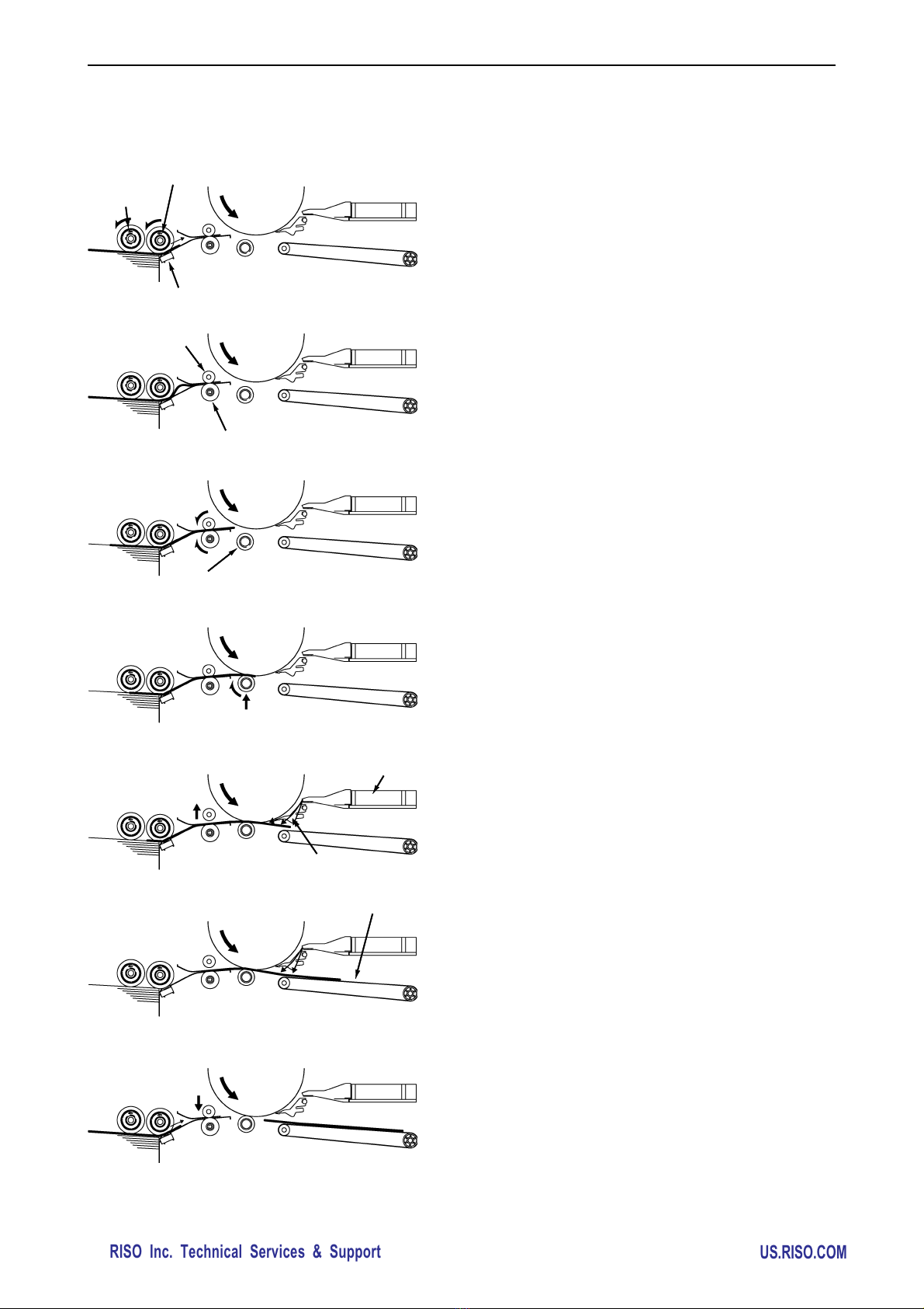
(1) When the print drum rotates, the scraper roller and
pickup roller also turn to feed paper. The stripper pad
allows only one sheet to pass through to the second
paper-feed area.
(2) The paper sent from the first paper-feed area contacts
the timing roller and guide roller, and stops temporarily.
This causes slight buckling of the paper.
(3) The timing roller and guide roller start rotating, feeding
paper to the pressure section. (This operation is referred
to as the “second paper-feed”. To prevent tension from
being placed on the end of the paper, the scraper roller
and pickup roller are free to spin.)
(4) When the paper is fed further in from the second paper-
feed area, the pressure roller rises to clamp the paper
between the drum and pressure roller to start the printing
operation.
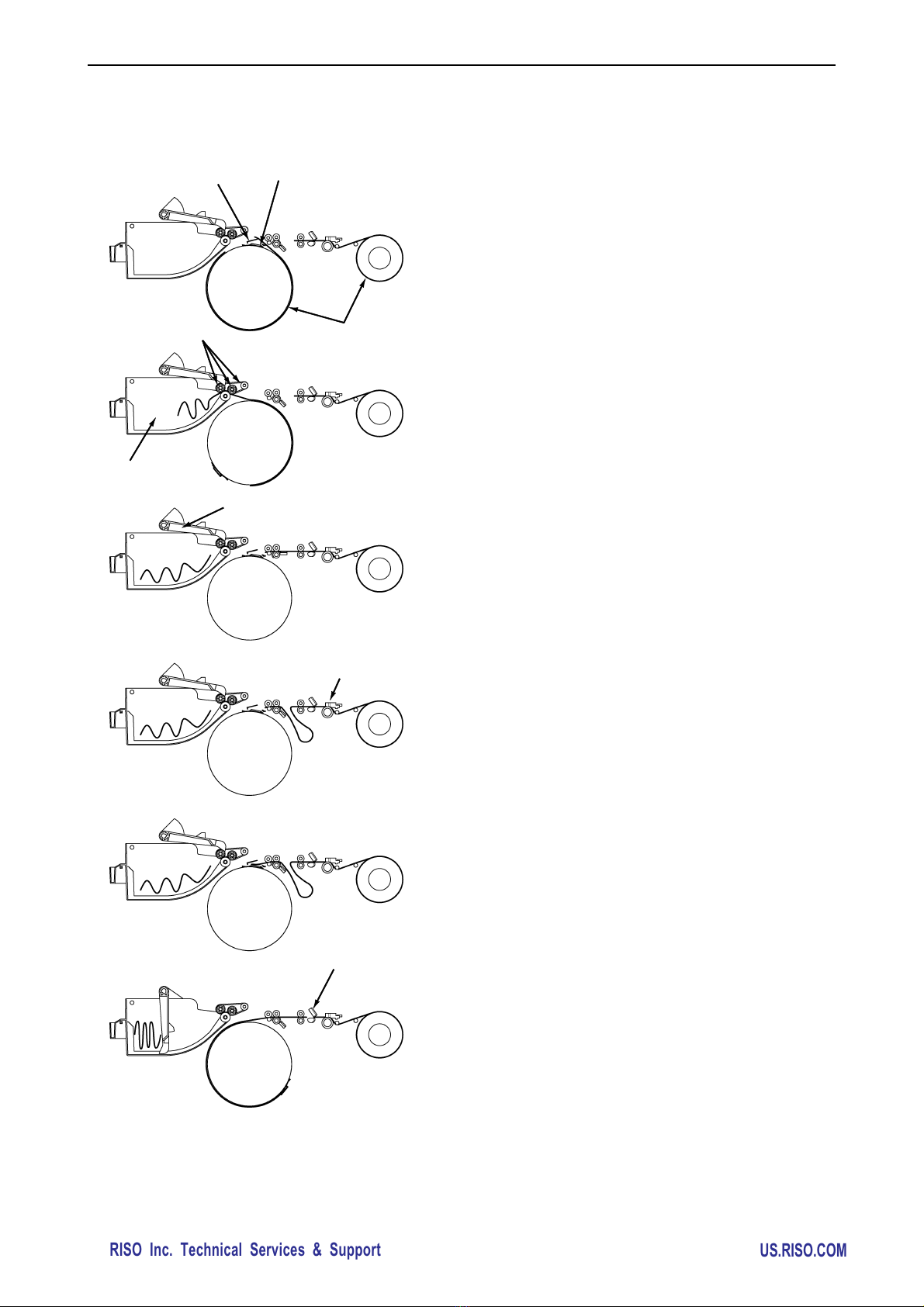
(5) The printed paper is removed from the print drum by the
separator and separation fan. When the pressure roller
rises, the guide roller also moves up to prevent tension
from being placed on the tailing end of the paper.
(6) Then, the suction fan sucks in the air to keep the paper
firmly on the transfer belts while the paper is carried to
the paper-receiving tray.
(7) The next sheet of paper is sent to the first paper-feed
area, and the guide roller lowers.
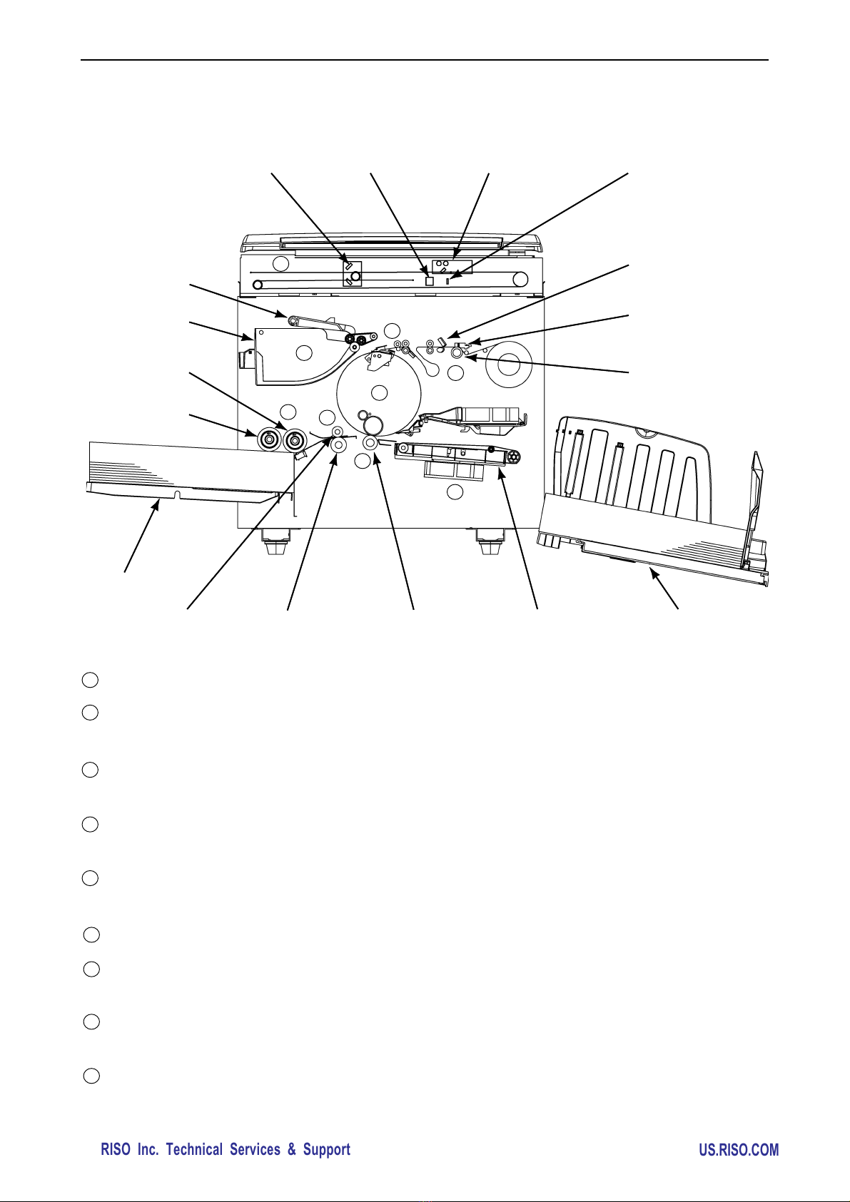
3. Outline of Paper-feeding, Printing, and Paper-ejection Operations
Scraper roller
Pickup roller
Stripper pad
Guide roller
Timing roller
Pressure roller
Separation fan
Separator
Transfer belt
0202

RISO Inc. Technical Services & Support
US.RISO.COM
CHAPTER 2: MACHINE SUMMARY
[ 2 - 5 ]
Master-removal operation
(1) The clamp plate holding the leading edge of the master
opens, and the master-release bar rises to lift the
master out from under the clamp plate
(2) The vertical transport rollers and print drum rotate,
thereby separating the master from the print drum and
sending it to the master disposal box.
(3) The motion of the compression plate starts, pressing
the master into the master disposal box.
Master-making operation
(1) The image sensor scans the original, and the thermal
print head transfers the image onto a master.
Master-loading operation
(1) The leading edge of the master is sent to a the clamp
plate on the print drum, and the leading edge is clamped.
(2) The print drum rotates to wind the master around it.
(3) The cutter cuts the master.
4. Outline of Master-removal, Master-making, and Master-loading Operations
Clamp plate Master -release bar
Master material
Vertical transport rollers
Master disposal box
Compression plate
Thermal print head
Cutter
0203

RISO Inc. Technical Services & Support
US.RISO.COM
[ 2 - 6 ]
CHAPTER 2: MACHINE SUMMARY
5. Optional Accessories (Excludes China Market Models)

RISO Inc. Technical Services & Support
US.RISO.COM
CHAPTER 2: MACHINE SUMMARY
[ 2 - 7 ]
6. Machine Specification (Excludes China Market Models)

RISO Inc. Technical Services & Support
US.RISO.COM
[ 2 - 8 ]
CHAPTER 2: MACHINE SUMMARY

RISO Inc. Technical Services & Support
US.RISO.COM
CHAPTER 2: MACHINE SUMMARY
[ 2 - 9 ]

RISO Inc. Technical Services & Support
US.RISO.COM
[ 2 - 10 ]
CHAPTER 2: MACHINE SUMMARY

RISO Inc. Technical Services & Support
US.RISO.COM
CHAPTER 2: MACHINE SUMMARY
[ 2 - 11 ]

RISO Inc. Technical Services & Support
US.RISO.COM
[ 2 - 12 ]
CHAPTER 2: MACHINE SUMMARY
7. Optional Accessories (China Market Models only)

RISO Inc. Technical Services & Support
US.RISO.COM
CHAPTER 2: MACHINE SUMMARY
[ 2 - 13 ]
8. Machine Specification (China Market Model only)

RISO Inc. Technical Services & Support
US.RISO.COM
[ 2 - 14 ]
CHAPTER 2: MACHINE SUMMARY
MEMO

RISO Inc. Technical Services & Support
US.RISO.COM
CHAPTER 3: MAIN DRIVE
[ 3 - 1 ]
CHAPTER 3: MAIN DRIVE
Contents
MECHANISM
1. Main Drive Section ............................................................................................................. 3-2
2. Print Drum Angle Detection ................................................................................................ 3-3
3. Main Motor Safety Mechanism ........................................................................................... 3-4
DISASSEMBLY
< Precautions to work safely on the drive area > ...................................................................... 3-6
1. Removing the Pressure Spring ........................................................................................... 3-7
2. Removing the Main Belt ..................................................................................................... 3-8
3. Removing the Main Motor Pulley Assembly ...................................................................... 3-10
4. Removing the Main Shaft Assembly ................................................................................. 3-11
5. Removing the Serviceman Safety SW ............................................................................. 3-12
ADJUSTMENT
1. Print-Drum <Position-A> Adjustment ............................................................................... 3-13
2. Print-Drum <Position-B> Stop Position Adjustment .......................................................... 3-13

RISO Inc. Technical Services & Support
US.RISO.COM
CHAPTER 3: MAIN DRIVE
[ 3 - 2 ]
Mechanism
1. Main Drive Mechanism
When the main motor is turned on, the motor pulley rotates and the rotation is transmitted to the main pulley
by the main belt. The main motor FG sensor detects the speed and the angle position of the print drum.
0301
0302
Main pulley
Main motor
Main motor FG sensor
Main belt
Motor pulley
< Main motor >
Table of contents
Other Riso Printer Accessories manuals