RITE-HITE BARRIER GLIDER 7100 User manual

BARRIER®GLIDER
SINGLE SLIDE COLD STORAGE DOOR
MODEL 7100
PRINTED IN U.S.A. PUBLICATION NO. 7100SSG
This Manual Covers Doors Shipped After 12-17-07, Refer to 7100SSF For Doors Prior.

BARRIER®GLIDER Single Slide Model 7100
2PUB. NO. 7100SSG FEBRUARY 2008
PRODUCT INTRODUCTION
TABLE OF CONTENTS
INSTALLATION INSTRUCTIONS . . . . . . . . . . . . . . . . . . . . . .3
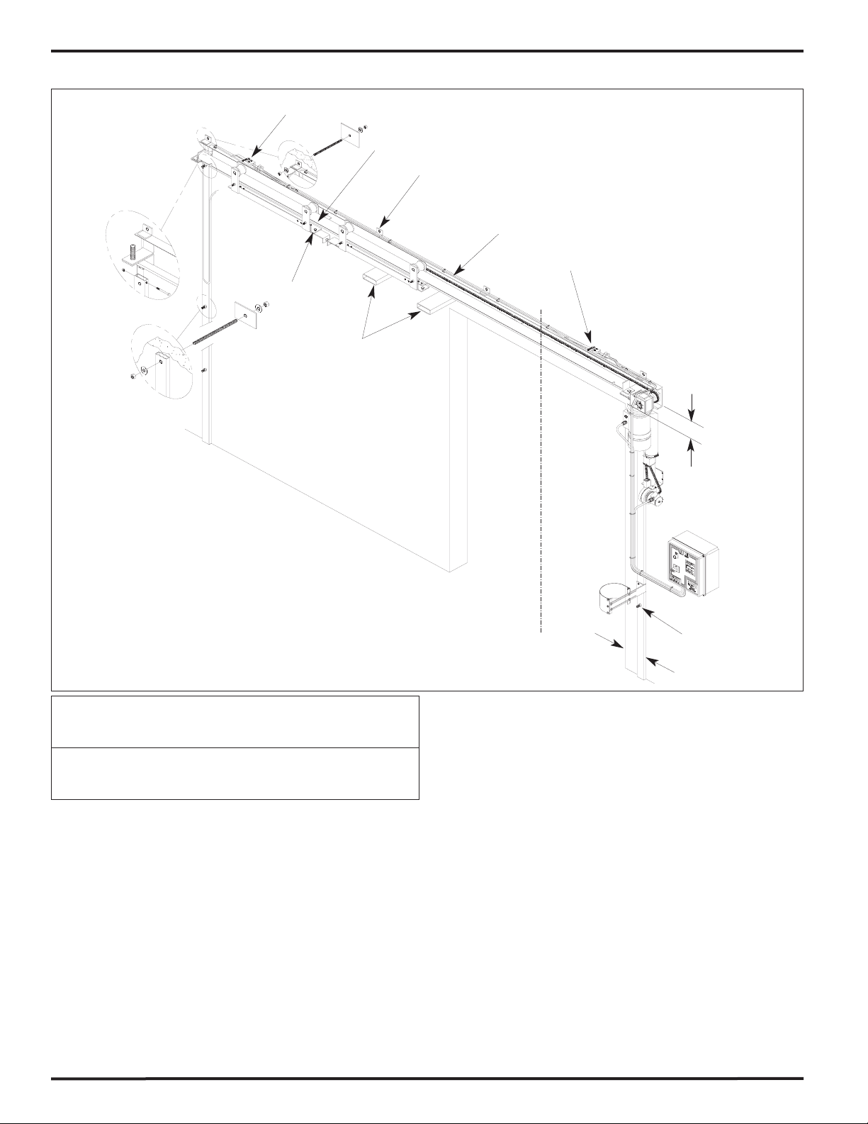
HEADER INSTALLATION . . . . . . . . . . . . . . . . . . . . . . . . . . . .4
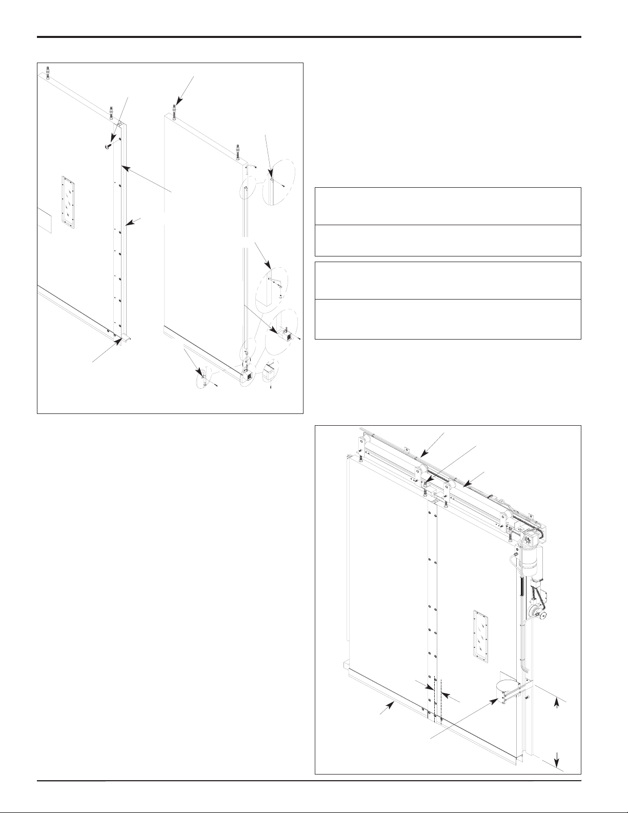
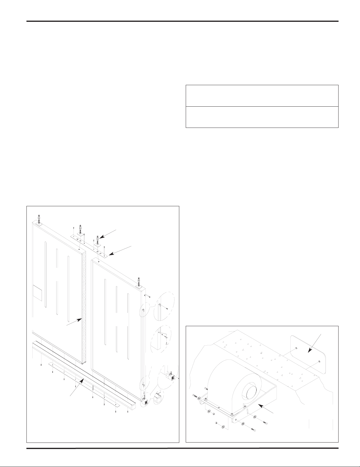
PERIMETER SEAL INSTALLATION . . . . . . . . . . . . . . . . . . . .6
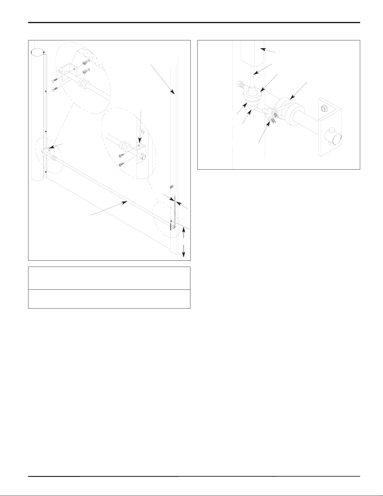
RETENTION SYSTEM INSTALLATION . . . . . . . . . . . . . . . . .7
PANEL INSTALLATION . . . . . . . . . . . . . . . . . . . . . . . . . . . . . .8
ELECTRICAL INSTALLATION . . . . . . . . . . . . . . . . . . . . . . . .10
INPUT / OUTPUT CHART . . . . . . . . . . . . . . . . . . . . . . . . . . .12
TROUBLESHOOTING / MAINTENANCE . . . . . . . . . . . . . . .13
FINAL CHECKLIST . . . . . . . . . . . . . . . . . . . . . . . . . . . . . . . .15
WIRING DIAGRAMS . . . . . . . . . . . . . . . . . . . . . . . . . . . . . . .16
ARCHITECTURAL DRAWING . . . . . . . . . . . . . . . . . . . . . . . .19
NOTICE TO USER
Our mission is to “Improve Industrial Safety, Security and
Productivity Worldwide Through Quality and Innovation.”
Thank you for purchasing the BARRIER®GLIDER from RITE-
HITE DOORS, INC. The BARRIER GLIDER is designed to be a
fast, smooth opening, low maintenance door that provides
superior environmental separation while reducing passage time
and temperature loss.
This manual should be thoroughly read and understood before
beginning the installation, operation or servicing of this door.
Complete Final Checklist prior to leaving site.
Refer to partslist manual for exploded views and part numbers.
This owners manual MUST be stored near the door.
RITE-HITE DOORS, INC. reserves the right to modify the
electrical and architectural drawings in this manual as well as
the actual parts used on this product are subject to
manufacturing changes and may be different than shown in this
manual. Due to unique circumstances with varying
requirements, separate prints may be included with the unit.
The information contained in this manual will allow you to
operate and maintain the door in a manner which will insure
maximum life and trouble free operation. The serial # for your
door is on a label located on the side of the control box and
support post.
Your local RITE-HITE DOORS, INC. Representative provides
the Planned Maintenance Program (P.M.P.) which can be fitted
to your specific operation. If any procedures for the installation,
operation or maintenance of the BARRIER GLIDER have been
left out of this manual or are not complete, contact RITE-HITE
DOORS, INC. Technical Support at 1-563-589-2722.
RITE-HITE DOORS, INC. are covered by one or more of the
following U.S. patents, including patents applied for, pending, or
issued: 5,025,846, 5,143,137, 5,203,175, 5,329,781, 5,353,859,
5,392,836, 5,450,890, 5,542,463, 5,579,820, 5,601,134,
5,638,883, 5,655,591, 5,730,197, 5,743,317, 5,794,678,
5,887,385, 5,915,448, 5,944,086, 5,957,187, 6,042,158,
6,089,305, 6,098,695, 6,145,571, 6,148,897, 6,192,960,
6,321,822, 6,325,195, 6,330,763, 6,352,097, 6,360,487,
6,574,832, 6,598,648, 6,612,357, 6,615,898, 6,659,158
SPECIAL FEATURES
• i-COMM™ Universal Controller
• Energy Efficient Design Featuring High R-Value Panels
• Flexible or High Security Fiberglass Panels
• Unique Thermal Air Sealing System
• Impactable Panel Retention System
• Universal Drive Side
RECOMMENDED SERVICE PARTS
Bottom Seal Panel Blower/Heater
Retention Cord Limit Switch
Fuses
INSTALLATION TOOLS REQUIRED
Fork and Scissors Lift
12’ Step Ladder
25’ Tape Measure
6’ Carpenters Level
Hydro Level
Cordless Drill
Wire Strippers
Utility Knife
Hammer
1/2” Masonry and/or Drill Bit for thru bolting
7/16”, 1/2”, 9/16” Open End and/or Socket Wrench
(2) 15/16” Open End Wrenches
11/16” x 12” Drill Bit for thru bolting
Straight Screwdriver (small 1/8” spade)
Hardware for mounting the header, support posts, retention rod,
blower and perimeter seals to wall are provided. Caulk for
perimeter seals is not provided.
WARRANTY
RITE-HITE DOORS, INC. warrants that it’s BARRIER®GLIDER
door will be free from defects in design, materials, and
workmanship for 150,000 cycles or for a period of one (1) year
from the date of shipment. The panel fabric warranty covers
material failure under normal wear conditions; it does not cover
labor or damage incurred from abuse, misuse or impact.
Warranty does not cover wear items such as seals, belts, fuses,
and bulbs. All claims for breach of this warranty must be made
within thirty (30) days after the defect is or can, with reasonable
care, be discovered. To be entitled to the benefits of this
warranty, the products must have been properly installed,
maintained, operated within their rated capacities, and not
otherwise abused. Periodic lubrication and adjustment are the
sole responsibility of the owner. This is RITE-HITE DOORS,
INC. exclusive warranty. RITE-HITE DOORS, INC. expressly
disclaims all implied warranties of merchantability and fitness.
Non-standard RITE-HITE DOORS, INC. warranties, if any, must
be specified by RITE-HITE DOORS, INC. in writing.
In the event of any defects covered by this warranty, RITE-HITE
DOORS, INC. will remedy such defects by repairing or
replacing any defective equipment or parts, bearing all of the
costs for parts, labor, and transportation. This shall be the
exclusive remedy for all claims whether based on contract
negligence or strict liability. Neither RITE-HITE DOORS, INC.,
RITE-HITE DOORS, INC. representatives or any other
manufacturer whose products are the subject of this
transaction, shall in any event be liable for any loss or use of
any equipment or incidental or consequential damages of any
kind whether for breach of warranty, negligence, or strict liability.
The application of a manufacturer's specifications to a particular
job is the responsibility of the purchaser.
RITE-HITE DOORS, INC.
8900 N. Arbon Drive
P.O. Box 245020
Milwaukee, Wisconsin 53224-9520
Sales: 414-355-2600
Toll Free: 800-456-0600
Aftermarket: 563-589-2781
Service: 563-589-2722
Service Fax: 563-589-2737
Representatives in All Major Cities
www.ritehite.com

BARRIER®GLIDER Single Slide Model 7100
PUB. NO. 7100SSG FEBRUARY 2008 3
INSTALLATION INSTRUCTIONS
It is important to verify the following basic information
before starting with the installation.
TO PREVENT DAMAGE TO CONTENTS, STORE DRY
BETWEEN 40° AND 80° F.
1. Make sure that you are working at the correct location and
that you have any special work permits.
2. Inspect the installation site to make sure that there are no
overhead obstructions (sprinkler pipes, HVAC systems,
electrical supply lines, etc.) that might interfere with the
lifting of the header assembly during installation.
3. Detour material handling equipment (fork lift trucks, etc.)
during the installation of the door.
4. Make sure that the electrician is ready to bring the
correct electrical power supply to the door control box.
5. Make sure that the electrical power can be shut off
without interfering with other plant operations.
6. Move the entire crate of the door components as close to
the door opening as possible.
7. When unpacking the door components remove the lighter
items first (electrical components), then the support
posts, and the header assembly last.
8. Measure the overall width of the door opening near the
floor and the top (Dimensions A and B), Figure 1.
9. Measure the height of the door opening at the left and
right-hand sides (Dimensions C and D), Figure 1.
10. These dimensions should be within ±1" of the dimensions
listed on the Serial Number label. If the measurements
do not agree, STOP! Contact your RITE-HITE DOORS,
INC. representative.
11. Using a 6’ carpenter’s level, verify that the door jambs
are plumb and perpendicular, the header and floor are
level, within ±1". If the floor is not level to within 1",
shimming of the support post will be required, Figure 1.
12. When removing the panels from the crates. Be sure not
to lean panels such that they crease.
13. Remove header from the crate by removing the front and
motor side of the crate. Slide the motor off the edge of the
crate and stand up. There will be a block under the C-
Channel to keep the motor off the floor, this will allow a
fork lift to pick up the header using the header lifting tubes.
14. Remove plastic rivets and keep in a warm place.
15. D.O.W. / H. = Door Opening Width / Height
16. O.D.W. / H. = Ordered Door Width / Height
17. Be sure to install optional equipment last after verifying
door operation.
NOTE: Check for electrical prints included in the parts or
control box, as they supersede any prints included
in this owners manual on Pages 16-18.
POLY LUMBER INSTALLATION
1. If the door is equipped with the optional poly lumber,
install per Figure 1A.
2. Caulk behind poly lumber that surrounds the opening.
3. Install vertical pieces at ordered door width and then
bottom horizontal piece at door ordered height.
4. Place small pieces behind header and support post tabs
after posts and header are in place.
LISTING OF MEASUREMENTS AND
MARKINGS REQUIRED
1. Door width at bottom
2. Door width at top
3. Door height left
4. Door height right
5. Mark left wall where water is level.
6. Mark right wall where water is level.
CD
Hydro-Level
A
B
48”
High Side Low Side
Level
FIGURE 1 Shim This Side
Make sure to barricade the door opening on both
sides to prevent unauthorized use until the door has
been completely installed.
CAUTION !!!
!
When working with electrical or electronic controls,
make sure that the power source has been locked out
and tagged according to OSHA regulations and
approved local electrical codes.
DANGER !!!
!
FIGURE 1A
Header Thru-Bolt Poly
Lumber Tab. Place Behind
Pre-Drilled Mounting Hole
Support Post Thru-Bolt
Poly Lumber Tab.
Place Behind Pre-
Drilled Mounting Hole
Horizontal Air Bag
Poly Lumber
Vertical Air Bag
Poly Lumber
D.O.W.
D.O.H.

NOTE: Figure 2 is for doors that the motor is mounted on
the jamb side, Figure 2A is for doors that the
motor is mounted on the storage side.
1. Place header in front of the opening, by locating the
factory assembled header lifting tubes bolted to the
bottom of the header.
NOTE: If bollard posts are present, and the lifting tubes
cannot be used, strap around the header tube. The
shorter support post is mounted to the header at
the side closest to the jamb. Insure that the header
is 7 1/2” above the opening at the end closest to
the jamb.
2. Lift the header using the fork lift and bolt the support
posts to the header (posts are free to slide up & down
within the c-channel bracket) and place against the wall,
Figure 2.
3. Plumb outside of jamb support post 9” past edge of jamb.
4. Thru-bolt the header to the wall at the (4) top and (2)
bottom mounting angles using the 6” x 6” backer plates,
all thread rods and nuts provided, Figure 2 or 2A. If wall
is not solid, sleeves (not provided) must be used to
prevent wall from crushing and sagging of the header.
5. Plumb and fasten the support posts to the wall in the
(4 or 6 based on O.D.H) locations provided with the 6” x 6”
backer plates, all thread rods and nuts provided,
Figure 2 or 2A.
6. After header and support posts have been installed,
remove the header lifting tubes and hardware.
BARRIER®GLIDER Single Slide Model 7100
4PUB. NO. 7100SSG FEBRUARY 2008
HEADER INSTALLATION
FIGURE 2 - JAMB SIDE DRIVE
Panel Trolleys
Panel Stud
Holes
Close Limit Switch
Open Limit Switch
Header
Jamb Side
Shorter
Support Post
Support Post
Header Mounting
Support Post Wall
Mounting (4-6 Places)
Header Mounting Angle
(6 Places)
C
L
Lifting Tubes, Make
Sure to Clamp or Tie to
Fork Lift and Remove
After Complete
9”
It is HIGHLY recommended to thru-bolt the header
with the all threaded rods provided, as this is the
main support for the door.
IMPORTANT!!!
7 1/2”

BARRIER®GLIDER Single Slide Model 7100
PUB. NO. 7100SSG FEBRUARY 2008 5
HEADER INSTALLATION
FIGURE 2A - STORAGE SIDE DRIVE
Panel Trolleys
Panel Stud
Holes Close Limit Switch
Open Limit Switch
Header
Support Post
Header Mounting
Support Post Wall
Mounting (4-6 Places)
Header Mounting Angle
(6 Places)
C
L
Lifting Tubes, Make
Sure to Clamp or Tie to
Fork Lift and Remove
After Complete
9”
7 1/2”
Jamb Side
Support Post
Cable Not
Present With
Cooler Door
Option

BARRIER®GLIDER Single Slide Model 7100
6PUB. NO. 7100SSG FEBRUARY 2008
NOTE: Figure 3 is for doors that the motor is mounted on
the jamb side, Figure 3A is for doors that the
motor is mounted on the storage side.
1. Position Thermal Air Sealing system in front of the
opening.
2. Place marks on top of the jamb at O.D.H. plus 5 3/8”.
3. Place marks at 1/2 D.O.W. plus 5 3/8” on the storage side
of the jamb, Figure 3 or 3A.
4. Place the outside of the perimeter seal retainers to the
wall on these marks and fasten every 18” using the
#14 x 1 1/4" hex head screws provided.
5. Make sure the top is centered and corners are not
binding.
6. Make sure vertical part of seal touches the floor on both
sides.
7. Mount the blower to the wall, so the vertical section will
attach to it, the fabric should be taught but not stretched
when clamping to the blower, Figure 3 or 3A. Use (4)
#14 x 1 1/4" hex head screws.
8. Fasten the retainer and the white rope of the seal to the
wall at the bottom, pull tight and fasten at the top to avoid
twisting or wrinkling of the bag, Figure 4.
9. After seal installation caulk the entire inside perimeter of
the aluminum retainer. Failure to do this may result in
frost or ice buildup.
PERIMETER SEAL INSTALLATION
FIGURE 3- JAMB SIDE DRIVE
Vertical Extension
Fastened to Blower
BOTH SIDES:
Air Outlet Hole
MUST Not Be
Obstructed.
Pull Seal Taught
and Tight to the
Floor and
Screw Retainer
to Hold in Place
D.O.W.
1/2 D.O.W.
O.D.H. + 5 3/8”
DOOR OPENING
L
C
Make sure that the bag is not twisted when installing.
Periodic cleaning of the perimeter air bag sealing
system may be required.
IMPORTANT!!!
5 3/8”
Retainer
Seal
Optional
Blockout
Screw Retainer to the
Wall After Fastening
at the Bottom
FIGURE 4
Air Bag
Seal
Exhaust Hole
w/ Grommet
Fasten Thru
Retainer and
Seal Rope
D.O.W. + 5 3/8”
Storage Side
Thermal Air®Sealing
System. Fasten Seal
Retainer Every 18”
FIGURE 3A- STORAGE SIDE DRIVE
Vertical Extension
to Blower
BOTH SIDES:
Air Outlet Hole
MUST Not Be
Obstructed.
Pull Seal Taught
and Tight to the
Floor and
Screw Retainer
to Hold in Place D.O.W.
1/2 D.O.W.
O.D.H. + 5 3/8”
DOOR OPENING
L
C
5 3/8”
Retainer
Seal
Optional
Blockout
Screw Retainer
to the Wall
After Fastening
at the Bottom
D.O.W. + 5 3/8”
Storage Side
Thermal Air®Sealing
System. Fasten Seal
Retainer Every 18”

BARRIER®GLIDER Single Slide Model 7100
PUB. NO. 7100SSG FEBRUARY 2008 7
1. Mount outside wall bracket on the support post, 16” from
the floor to the top of the bracket and 3/4” from the
outside of the post with the self tap/drill screws provided.
2. Mount inside bracket on the wall with angle tight against
the retention rod bolt and 16” from the floor to the top of
the bracket, Figure 5. Make sure mounting method will
hold if panel is impacted.
3. The panel eyebolt should be approximately 3 1/2” above
the center of the slide rod.
4. Slide eyebolt insert onto cord with insert facing up.
5. To pre-tension the spring, pull 6” of cord out, tie a knot
below the eyebolt insert and then wrap around the slide
collar and fasten with cable clamp, cut excess cord,
Figure 6.
6. Cord should be tensioned to maintain a 3 1/2” gap from
the panel to the wall.
FIGURE 6
Cord
Eyebolt
Eyebolt Insert
Slide Collar
Cord Clamp
Spring Assembly
Maintain 3 1/2” gap from wall to panel to provide ideal
seal.
IMPORTANT!!!
Cord Knot
FIGURE 5
Longer
Support Post
Retention Rod
Retention
Rod Bracket
Slide Angle
Tight
Against Bolt
3/4”
16”
RETENTION SYSTEM INSTALLATION

BARRIER®GLIDER Single Slide Model 7100
8PUB. NO. 7100SSG FEBRUARY 2008
NOTE: Panels will come as two pieces.
1. With the cord at the bottom, fasten retention spring
assembly to the outside of the trail panel by lining up the
pre-drilled holes in the extrusion with the pre-marked
holes on the panel. Use the #14 x 1 1/4" self/tap drill
screws provided, Figure 7.
2. Fasten eyebolt and nut to the panel in the pre-tapped
hole, Figure 7.
3. Fasten the blower assembly to the panel using
(1) #14 x 1 1/4" self/tap drill screw provided and connect
plugs, Figure 7.
4. Remove the top 5/8” nut (15/16” wrench) from threaded
rods.
5. Place the lead panel in front of the opening with the all
thread rods at the top, Figure 8.
6. Separate the trolleys by removing the bolt & nuts
connecting them together.
7. Tilt panel such that the all thread rods will slide into the
holes on the trolley, fasten with nuts and washers
removed earlier.
8. The panel should be adjusted so that the seal is
compressed no more than 1/4” - 3/8” and no light is
showing across the full length of the floor when closed.
9. Apply a generous bead of caulk down the middle of the
rear edge of the lead panel.
10. Place marks along inside vertical edge of trail panel,
1 5/8” in from edge of panel.
11. Set trail panel on top of lead panel lower bracket, slide trail
panel into “H” bracket until the 1 5/8” marks disappear.
NOTE: The top of the panels can be pulled together with
the trolley to trolley attachment bolt at the top that
was removed earlier. If panels are not tight together,
remove spacer nut, Figure 8.
12. Attach the trail panel by drilling 17/64” holes in the pre-
drilled holes on the “H” bracket and inserting the plastic
rivets. DO NOT DRILL THRU PANEL.
13. Attach the panels and bottom seal flap together by drilling
17/64” holes through the pre-drilled holes in the overlap
flap, plastic and aluminum, then inserting two plastic rivets.
PANEL GUIDE
1. Fasten panel guide to the support post so it is centered
on the panel wear pad, Figure 8.
2. To adjust, loosen bolts and slide in slots so panel is tight
against the wall seal.
FIGURE 8
Lead Panel
Stud, Nuts, Washers
Panel Guide
Bottom Seal
Trail Panel
Header
Panel Trolley
FIGURE 7
Bottom Seal Fan
Not Present With
Cooler Door
Option
Spring Assembly
Fan Cable
Attachment
Cord/Eyebolt Insert
After panel is adjusted, torque nuts as tight as
possible to prevent loosening from vibration and seal
loss.
IMPORTANT!!!
Stud, Nuts and Washers
Panel Splice
“H” Bracket
Panel Splice
Rivet
Trail Panel
Lead Panel
Set Trail Panel Here for
Proper Height Location
Center
of
Wear
Pad
Apply Caulk Here
DO NOT use excessive force when hammering rivets
into place, as distortion may occur.
IMPORTANT!!!
5 1/4”
FLEXIBLE PANEL INSTALLATION

NOTE: Panels may come as one or two piece, depending
on the width of the opening.
The fiberglass panels will be shipped without the
nose and bottom seals attached.
Panels are heavy, use caution when moving
and installing.
1. Apply a generous bead of caulk to the rear edge of the
lead panel.
2. Lay the two panels together on a flat surface and butt
them up for a tight fit.
3. Attach the splice bracket between the two panels at the
top.
4. Fasten bottom seal to the bottom of the panel every 12”
with the Screw, HWH, Dr/Tap, #14 x 1 1/4” provided.
5. With the cord at the bottom, fasten retention spring
assembly to the outside of the panel by lining up the pre-
drilled holes in the extrusion with the pre-marked holes
on the panel, Figure 9.
6. Fasten eyebolt and nut to the panel in the pre-tapped
hole, Figure 9.
7. Fasten the blower assembly to the panel using
(1) #14 x 1 1/4" self/tap drill screw provided and plug
cable together, Figure 9.
8. Remove the top nut from threaded rods.
9. Place panel in front of the opening with the threaded rods
at the top, Figure 8.
10. Tilt panel such that the threaded rods will slide into the
holes on the trolley, fasten with nuts and washers
removed earlier.
11. The panel should be adjusted so that the seal is
compressed no more than 1/4” - 3/8” and no light is
showing across the full length of the floor when door is
closed.
VISION FAN OPTION
1. Mount fan minimum 3” above header and on the center
of the opening. It is recommended to thru-bolt to the wall.
2. 120V, 12 gauge cable with a ground is encouraged for
the power supply (not supplied).
3. Use the adjustable bracket to aim airflow at the vision,
Figure 10.
BARRIER®GLIDER Single Slide Model 7100
PUB. NO. 7100SSG FEBRUARY 2008 9
FIBERGLASS PANEL INSTALLATION
After panel is adjusted, torque nuts as tight as
possible to prevent loosening from vibration and seal
loss.
IMPORTANT!!!
FIGURE 9
Bottom Seal
Fan Not Present
With Cooler
Door Option
Spring
Assembly
Bottom Seal
Cord/Eyebolt
Insert
Panel Hanger Stud,
Nut and Washer
Lead
Panel
Trail
Panel
Splice Bracket
Caulk Between
Panels
FIGURE 10
Wall
Backer Plate
Blower Mounted 3”
Minimum Above Header

BARRIER®GLIDER Single Slide Model 7100
10 PUB. NO. 7100SSG FEBRUARY 2008
The BARRIER-GLIDER has been factory tested. The
cables from the door are ready to be connected to the
control box. Please study the electrical wiring diagrams
on Pages 16 - 18.
1. Local electrical codes may require the use of rigid conduit
or a junction box when running the electrical cables from
the header down to the control box. Drill a hole for the
power supply (by others) in the bottom of the control box,
Figures 12 & 13.
2. It is the responsibility of the buyer to provide service up
to the box with proper branch service protection and an
approved means of disconnect. See amperage chart on
Page 18.
3. All boxes should be mounted on the warm side or on the
wall adjacent to the door past the support post at
approximately 54" above the floor level, Figure 12.
4. The control box is provided with class CC protective
fusing for the incoming power.
5. The incoming power terminals F1, F2, F3 in the control
box will not accommodate wires larger than 10AWG.
Connect wiring as indicated by the device field wiring
schematic.
6. The motor and limit switch cables are prewired to each
component and will need to be run to a watertight fitting
(not provided) in the bottom of the control box, and hard
wired, Figures 12 & 13.
7. Cut the cable tie holding the panel blower/heater cable
and loop the panel blower/heater cable around the panel
adjustment bolt and secure with a cable tie for strain
relief. Connect cables together.
8. This door is powered by 220/575VAC 1Ø or
208/230/460VAC 3Ø.
ELECTRICAL INSTALLATION
In freezer and cooler applications where a
conduit passes from a warm to cold temperature
zone, the conduit must be plugged with epoxy. This
will help prevent condensation from forming in the
conduit. For more information, see Section 300-7a of
the National Electric Code.
IMPORTANT!!!
FIGURE 12
Support Post
Floor
Door cables, activation devices
etc. Conduit run by others.
Fused disconnect (supplied by
others), located next to where
the control box will be located.
54” - Control box
recommended
mounting height
and minimum of
6” from support
post
See Pages 16-18 for required
voltage and service amperage
requirements given your
specific line voltage.
When working with electrical or electronic controls,
make sure that the power source has been locked out
and tagged according to OSHA regulations and
approved local electrical codes.
WARNING!!!
!
When drilling holes in the box, DO NOT turn control
box upside down or go too deeply into the box.
Damage or debris may fall into electrical components
causing failure or severe equipment damage.
CAUTION !!!
!
A qualified electrician should install the wiring in
accordance with local and national electrical codes.
Use lockout and tagout procedures to avoid injury.
IMPORTANT!!!
To reduce risk of injury or death, an earth ground
connection MUST BE made to the green/yellow control
box ground terminal. If metal conduit is used as the
ground connector, an N.E.C. approved ground bushing
and green/yellow wire MUST BE properly attached to
the conduit for connection to the ground terminal.
IMPORTANT!!!

BARRIER®GLIDER Single Slide Model 7100
PUB. NO. 7100SSG FEBRUARY 2008 11
ELECTRICAL INSTALLATION
FIGURE 13
F1, F2, F3
Incoming Power
DO NOT Wire
Incoming Power Into
These Terminals
575V 220V
208/230/460V

BARRIER®GLIDER Single Slide Model 7100
12 PUB. NO. 7100SSG FEBRUARY 2008
OPERATING PROCEDURE
1. To operate the door, simply press the green open button
on the front of the control box, the door should go to the
full open position.
2. Normal settings are set to auto-reclose, and once the
open button is pressed the door will open, time out per the
setting of the re-close timer on the i-COMM and close.
3. The door can be equipped with several types of
activation devices that can open or close the door and
can be setup to either auto-reclose or toggle mode.
4. For toggle mode, the door can be setup such that if a
device is used to open the door, it or another device
needs to be reactivated to close the door.
DRIVE CHAIN ADJUSTMENT
Find the center bracket of the header C-Channel. Chain
should be tensioned so there is 1” between the bottom of
the chain and the bottom of C-channel.
LIMIT SWITCH ADJUSTMENT
1. After all parts have been assembled to the door, place
the door in the closed position with the closed limit switch
tripped.
2. Open the door and set the open limit so the panels are
clear of the opening, Figure 14.
3. Limit switches are preset at a 10° angle toward each other.
INPUT / OUTPUT CHART / OPERATING PROCEDURE
FIGURE 14
Panel
Header
Limit Switch
Connection

BARRIER®GLIDER Single Slide Model 7100
PUB. NO. 7100SSG FEBRUARY 2008 13
TROUBLESHOOTING / MAINTENANCE
RITE-HITE®DOORS PLANNED MAINTENANCE
Model 7100 BARRIER®GLIDER
CUSTOMER: SO# SERIAL# DATE:
Periodic Cycle Check:
Planned Maintenance
Air Bag System
Blower
Blower Heater
Door Fasteners
Drive Chain
Gearbox
Limit Switches
Panel
Panel Nose and Bottom Seals
Panel Retention System
Torque Reversing Edge
Trolley Rollers
Recommended P.M. Intervals
(Time Shown In Months)
1
Inspect and Perform the Following (See Manual)
Make sure air flow thru the system is adequate. Air bag
may require periodic cleaning.
Perform visual inspection.
Check air temperature.
Perform visual inspection, check for proper width
dimension and tighten all bolts.
Lubricate, check tension and wear. Find the center
bracket of the header C-Channel. Chain should be
tensioned so there is 1/8” between the bottom of the
chain and the nylon wear pad.
Check lube, add if required.
Check open and close positions.
Check for damage, repair any tears to prevent moisture
or frost build-up. Make sure panel hanger bolts are tight.
Check for proper sealing, and tears and repair.
Make sure spring, cord and rod are functional and panel
is tight to the air bag, with no air leaks.
Check that door reverses at the nose.
Inspect for wear or binding.
4
•
•
•
•
•
•
•
•
•
•
•
•
8
•
12
•
•
•
•
•
•
•
•
•
•
•
•
18
•
24
•
•
•
•
•
•
•
•
•
•
•
30
•
36
•
•
•
•
•
•
•
•
•
•
•
•
DEFINITION FUNCTION
Drive Chain Make sure the drive chain is kept taught, but not so tight as to place stress on the shaft, sprocket or
tensioner, Page 12.
F1, F2, F3 Incoming power fuses.
F4, F5 Fuses for primary side of transformer.
F6 Fuse for the i-Comm 24VAC.
F7 120V Fuse from secondary side of transformer that supplies bridge rectifier and power supply.
F8, F9 Fuses for the Panel Heater, 10amp slow blow glass fuses.
i-COMM Controller™ The i-COMM controller is a circuit board that controls the actions of the door. There is a digital display
that shows the cycles, status and position of the door at any time during its travel. For input and output
function signals, refer to the chart on this page. Settings can be changed for re-close or pre-announce
timers, interlocks, special activation commands, among many others, refer to instructional manual
included.
Limit Switches Check limit switch position to make sure the door stops in the desired position. Red cable is for open
and grey is for closed switch.
Motor The motor is AC.
Panel The panels can be either a 3” flexible Iso-Tek panel or a 4” rigid Barrier panel. The rigid version is a
high security panel. Repair any tears to prevent foreign matter buildup and temperature loss.
Panel Blower/Heater Panel Blower/Heater provides warm air to keep the bottom seals warm and dry. Entire unit must be
replaced if blower or heater goes bad.
Panel Retention System The panels are held against the Perimeter Air Seal by a cord that is spring loaded on the panel and
slides on a rod along the wall. When impacted, the panel swings out and back toward the perimeter
seal when the impact object is removed.
Panel Reversing System When the panels impact an object in the opening, the door will reverse and go open. This should be
set so as not to damage any product or personnel that may be in the opening.
Reclose Timer Adjust through i-COMM controller.
Thermal Air Sealing System The Thermal Air Sealing System provides a seal between the panel and the wall by utilizing a
110VAC blower/heater system to provide heated air to fill the bag, thereby maintaining the seal and
minimizing any moisture buildup. Power to the blower must be constant. Make sure air exhaust hole is
free of obstructions, blockage my cause frost buildup. Repair any tears or replace as necessary.
Trolley To remove trolleys or replace rollers, remove the bottom plates and pull off.

BARRIER®GLIDER Single Slide Model 7100
14 PUB. NO. 7100SSG FEBRUARY 2008
INVERTER ERROR CODES / PROGRAMMING
Barrier Glider - Inverter Error Codes
Trip Code Condition Possible Cause
tr UU DC bus under voltage Low AC supply voltage, check power source.
Low DC voltage when supplied by an external DC power supply.
tr OV DC bus over voltage The DC bus (Pr. 84) has exceeded 800V-460V or 400V-230VAC, check the following:
If DC bus climbs while door is not running, disconnect CE filter with power off.
If fault is intermittent when door is not running try to set Automatic reset of faults.
(PR. 73 = 10.34, PR. 74=10.36, PR. 63 = 3, PR 64 = on) Deceleration rate set too fast
for the inertia of the machine. Mechanical load driving the motor.
tr It. AC I2C on drive output Motor wiring, check for loose connections or shorts.
Make sure door cannot move if brake is engaged.
tr OI.AC Drive output instantaneous Door is binding or jammed. Motor wiring, check for loose connections or shorts.
over current Make sure door cannot move if brake is engaged. Disconnect CE filter with power off.
Insufficient ramp times. Phase to phase or phase to ground short circuit on the drives
output. Drive requires autotuning to the motor. Motor or motor connections changed,
re-auto tune drive to motor. MUST wait 10 seconds to reset after trip occurs
O.SPd Over speed Excessive motor speed (typically caused by mechanical load driving the motor)
tunE Auto tune stopped before complete Run command removed before autotune complete
It.AC I2-t on drive output current Excessive mechanical load. Drive requires re-autotuning to motor.
High impedance phase to phase or phase to ground short circuit at drive output.
O.ht1 IGBT over heat based on Overheat software thermal model
drives thermal model
O.ht2 Over heat based on drives heatsink Heatsink temperature exceeds allowable maximum
th Motor thermistor trip Excessive motor temperature
O.Ld1 User +24V or digital output overload Excessive load or short circuit on +24V output
The Enable/Reset terminal will not reset an O.Ld1 trip. Use the Stop/Reset key.
OUL.d I x t overload Reduce motor current
hot Heatsink/IGBT temp is high Reduce ambient temperature or reduce motor current
br.rS Braking resistor overload See Advanced user guide
EEF Internal drive EEPROM failure Possible loss of parameter values
PH Input phase imbalance or One of the input phases has become disconnected from the drive
input phase loss
rS Failure to measure motors Motor too small for drive
stator resistance Motor cable disconnected during measurement
O.cL Overload on current loop input Input current exceeds 25mA
tr HF ## Hardware Fault The drive has detected a hardware problem, verify wiring is correct. This cannot be
fixed in the field, replace the drive.
HF 05 trip No signal from DSP at start up
HF 06 trip Unexpected Interrupt
HF 07 trip Watchdog failure
HF 08 trip Interrupt crash (code overrun)
HF 11 trip Access to the EEPROM failed
HF 20 trip Power stage - code error
HF 21 trip Power stage - unrecognized frame size
HF 22 trip Ol failure at power up
HF 25 trip DSP Communications failure
HF 26 trip Soft start relay failed to close, or soft start monitor failed or braking IGBT short circuit at power up
HF 27 trip Power stage thermistor fault
HF 28 trip DSp software overrun
HF xx trip HF 1-4, 9-10,12-19,23,24,29,30 Are not used
Barrier Glider™ Inverter Program Instructions
When in Status mode, pressing and holding the “M” MODE key for 2 seconds will change the display from displaying a speed indication to
displaying load indication and visa versa.
Pressing and releasing the “M” MODE key will change the display from status mode to parameter view mode. In parameter view mode, the left
hand display flashes the parameter number and the right hand display shows the value of that parameter.
Pressing and releasing the “M” MODE key again will change the display from parameter view mode to parameter edit mode. In parameter edit
mode, the right hand display flashes the value in the parameter being shown in the left hand display.
Pressing the “M” MODE key in parameter edit mode will return the drive to the parameter view mode. If the “M” MODE key is pressed again then
the drive will return to status mode, but if either of the “UP” or “DOWN” keys are pressed to change the parameter being viewed before the “M”
MODE key is pressed, pressing the “M” MODE key will change the display to the parameter edit mode again. This allows the user to very easily
change between parameter view and edit modes whilst commissioning the drive.
"WARNING: Consult factory before changing any parameters not listed in this table."
Parameter Number Name Default Value New Value Units
00.10 Security Status L1 L3
00.19 Closing Speed 0 30 s/100 Hz
00.20 Open Speed 0 60 S/100 Hz
00.61 Torque Detection Level 0 23 %
Barrier Glider - Status Modes
Left Display Status Explanation
rd Drive ready The drive is enabled and ready for a start command. The output bridge is inactive.
ih Drive inhibited The drive is inhibited because there is no enable command, or a coast to stop is in
progress or the drive is inhibited during a trip reset.
Er Drive has tripped The drive has tripped. The trip code will display in the right hand display.
dC Injection braking DC injection braking current is being applied to the motor.
Fr Drive output frequency in Hz
SP Motor speed in RPM
Ld Load current as a % of motor rated load current
A Drive output current per phase in A

BARRIER®GLIDER Single Slide Model 7100
PUB. NO. 7100SSG FEBRUARY 2008 15
LOCK INSTALLATION / FINAL CHECKLIST
CHECKLIST:
NOTE:
After the door installation is complete, the following
MUST BE confirmed before the door is ready for
operation.
1. The bottom seal should be touching the floor with
approximately 1/4”-3/8” compression with no visible light
showing. Make sure air is flowing thru the exhaust hole.
2. 6” of pre-tension should have been applied to the spring
by pulling out the rope, inserting the eyebolt insert and
tying a knot to keep the insert in place and maintain the
proper 3 1/2” distance from panel to wall.
3. Air bag should be tight to the floor, exhaust hole, clear
and free of obstructions and a screw fastened thru the
aluminum retainer and the seal rope to prevent from
sliding.
4. Air bag pulled up to remove any twists or wrinkles and
screw fastened thru the aluminum retainer and the seal
rope to prevent from sliding.
5. Aluminum retainer caulked to prevent cold air infiltration
and frost or ice developing.
6. Panel hanger nuts tightened to prevent them from
loosening up, resulting in seal loss.
7. Panel blower/heater cables wrapped around panel
hanger bolts and wire tied, per Figure 14.
OPTIONAL DRIVE SHROUD INSTALL
1. Install drive shroud after installation and adjustments are
complete.
2. Lift cover and set on stud at the top, fasten to the support
post, Figure 15. Use #14 x 1" hex head self/tap drill
screw.
Lock is for Rigid Panel only !!
Install lock per illustration
1. Only attempt to install this lock at the rear edge of a rigid panel.
2. Mount the panel lock bracket to the rear of the panel with the U-shaped
edge overlapping the retainer extrusion. The bracket needs to be centered
42” from the bottom of the panel, excluding the bottom seal. Pre-drill the
mounting holes with a 13/64” drill bit and install the assembly with the
security screws included.
3. With the door fully closed and power off, hold the mating lock piece
against the wall and align it with the panel bracket so when the swivel arm is
extended 90° from the wall, the padlock hole in the panel bracket lines up
with the slot in the swivel arm.
4. Mark the locations of the (2) mounting holes on the wall for thru-bolting
the wall mount lock bracket.
5. Drill 9/16” holes through the wall and attach the lock swivel arm assembly
with the fiberglass all-thread and backer plates included. The fixed nut on
the all-thread needs to be mounted on the same side as the bracket.
6. Confirm that when the swivel arm is released that it freely falls down and
is parallel with the wall.
Switch for Single Slide
or Bi-Parting Non-Drive
Switch for Bi-Parting Drive Side
FIGURE 15
Drive Shroud
1 1/2” Gap on
Backside for Air Flow
Fasten to
Support Post
Top Drive Shroud
Fastener, Install
Carriage Bolt to Hole in
Gearbox

BARRIER®GLIDER Single Slide Model 7100
16 PUB. NO. 7100SSG FEBRUARY 2008
MANDATORY FIELD WIRING DIAGRAM
PART #
MODEL NUMBER
C
R
REV
SHEET
DWG NO
BY APPROVED
DATEECNDESCRIPTION
REVISION HISTORY
REV
1234
43 1
DESCRIPTION
QTY PART NO.
ITEM
PARTS LIST / MATERIAL
NEXT ASSEMBLY
REV
SHEET
UP TOOVER
INCH TOLERANCES
+ / - DO NOT SCALE DRAWING
TITLE
DATE
DATE
MM-DD-YY
SIZE
SCALE
B
CHECKED BY
APPROVED BY
DRAWN BY
REF
INITIAL ECN
DATE ISSUED
0.25
5
1.25
15
80
40
0.125
0.25
1.25
5
15
40
-
FINISH
ANGLES +/- 1 DEG
80
0.040
0.060
0.100
0.125
0.010
0.020
0.030
0 0.125 0.005
DWG NO
DATE
RITE-HITE DOORS INC.
8810E035
8810E035
1"=1"
A
A
BARRIER GLIDER VFD
MANDATORY FIELD WIRING DIAGRAM
i-COMM
LIP 10/18/2007
10/18/2007
2007
ARENAME HEATER NEUTRAL 5602 2/8/2008 LIP

BARRIER®GLIDER Single Slide Model 7100
PUB. NO. 7100SSG FEBRUARY 2008 17
ACTIVATION WIRING
Wire
Nut
Bi-Parting Doors Only
RED wire
removed
from
Wire
Nut
RED
WHT
BLK #2
Control Box
BLK #1
Lock
Single Slide Doors Only
RED wire
removed
from
Wire
Nut
RED
Control Box
BLK
Lock
8810E034
8"=1'
BARRIER GLIDER VFD
ACTIVATION WIRING DIAGRAM
i-COMM
LIP 10/18/2007
10/18/2007
2007
ITEM QTY PART# DESCRIPTION CONDITION
1
5 15650179 CABLE,14/7,600V,90C
2 16960014 FTG,STRT,L/T,16MM
2
138120006 DIN RAIL,LOW-PROFILE,6-1/2
143750124 ENCL,LEXAN,7X5X4
267850015 SCR,PHLP,DR/TP,#8X1/2
1 51000003 FUSE HOLDER,2POLE,600V,30A +
2 51000051 FUSE,15AMP,600V,KLDR 208-230V
251000055 FUSE,6A,600V,CC,KLDR 460-575V
3153850268 LABEL,DANGER,HIGH VOLTAGE
4
2 73100024 TERMINAL,END STOP,SCREWLESS
2 73100072 TERMINAL,PH,CAGE,20A,3HOLE
173100073 TERMINAL,PH,CAGE,20A,3HOLE,BAR
273100076 TERMINAL,PH,CAGE,20A,3HOLE,GND
5
5 51950003 WIRE NUT, ORANGE
1 73550017 XFMR,2.0KVA,600:240/120 575V
173550024 XFMR,2.0KVA,480/240:240/120 Not 575V
PART #
MODEL NUMBER
C
APPROVEDBY
C
R
REV
SHEET
DWG NO
DESCRIPTIONQTY PART NO.
ITEM
PARTS LIST / MATERIAL
NEXT ASSE MBLY
D
C
B
A A
D
C
REV
REVISION HISTORY
DESCRIPTION ECN DATE APPROVED
BY
DATE
DWG NO
0.0050.1250
0.030
0.020
0.010
0.125
0.100
0.060
0.040
80
+/- 1 DEG
ANGLES
FINISH
-
40
15
5
1.25
0.25
0.125
40
80
15
1.25
5
0.25
INITIAL ECN
REF
DRAWN BY
CHECKED BY
SCALE
SIZE
MM-DD-YY
DATE
DATE
TITLE
DO NOT SCALE DRAWING
+ / -
INCH TOLERANCES
OVER UP TO
SHEET
REV
R
DATE ISSUED
RITE-HITE DOORS INC.
8810E032
8810E032
RITE-HITE
DOORS INC.
1"=1"
BARRIER GLIDER DEFROST
TRANSFORMER STEP-DOWN BOX
5360.X
LIP
8/14/2007
8/14/2007
2007

BARRIER®GLIDER Single Slide Model 7100
18 PUB. NO. 7100SSG FEBRUARY 2008
WIRING DIAGRAM

BARRIER®GLIDER Single Slide Model 7100
PUB. NO. 7100SSG FEBRUARY 2008 19
ARCHITECTURAL DRAWING (FLEXIBLE PANEL)
DOOR SYSTEM
8806A001
RITE-HITE
DOORS INC.
3/8"=1'
D
D
ARCHITECTURAL APPROVAL,
BARRIER GLIDER, SINGLE SLIDE, FLEXIBLE
PANEL, NON-STORAGE SIDE MOTOR MOUNT
2/9/2004
4409
4/8/2004
2004
D AC DRIVE 5529 1/15/2008 LIP
B ADDED VISION FAN DIMENSIONS 4575 9/13/2004 CDH
C UPDATE TITLE BLOCK 4603 11/15/2004 JTD
DOOR SYSTEM
8806A003
8806A003
RITE-HITE
DOORS INC.
3/8"=1'
A
A
ARCHITECTUAL APPROVAL
BARRIER GLIDER, SINGLE SLIDE, FLEXIBLE
PANEL, STORAGE SIDE MOTOR MOUNT
10/1/2004
4603
11/15/2004
2004
A AC DRIVE 5529 1/15/2008 LIP

8806A004
8806A004
RITE-HITE
DOORS INC.
3/8"=1'
A
A
ARCHITECTURAL APPROVAL
BARRIER GLIDER, SINGLE SLIDE, FIBERGLASS
PANEL, STORAGE SIDE MOTOR MOUNT
10/4/2004
4603
11/15/2004
2004
A AC DRIVE 5529 1/15/2008 LIP
DOORSYSTEM
DOOR SYSTEM
RITE-HITE
DOORS INC.
A REMOVE DIMENSION 'A' AND UPDATE 4483 7/1/2004 JTD
BUPDATE TITLE BLOCK 4603 11/15/2004 JTD
CAC DRIVE 5529 1/15/2008 LIP
ARCHITECTURAL DRAWINGS (RIGID PANEL)
20 PUB. NO. 7100SSG FEBRUARY 2008
BARRIER®GLIDER Single Slide Model 7100
Table of contents
Other RITE-HITE Door Opening System manuals
Popular Door Opening System manuals by other brands

Assa Abloy
Assa Abloy Rixson Smok-Chek VI Installation and instruction manual

argenta
argenta PIVOTICA PRO manual

Tormax
Tormax iMotion 1301.FIRE Instructions for use

Assa Abloy
Assa Abloy Corbin Russwin DC3200 Series installation instructions

Brookfield Industries
Brookfield Industries NB-500 manual

GEZE
GEZE ECturn Wiring diagram

CDVI
CDVI ERONE UTILE EAUTBTIG3 installation manual

Helm
Helm GT-L 80 H 412 installation instructions

Ribind
Ribind VERTIGO 8 manual

Chamberlain
Chamberlain LiftMaster Professional RDO800 Series Installation and operating instructions

Falcon
Falcon SC71 Series installation instructions

CRL
CRL H100E10 Instruction of Assembly