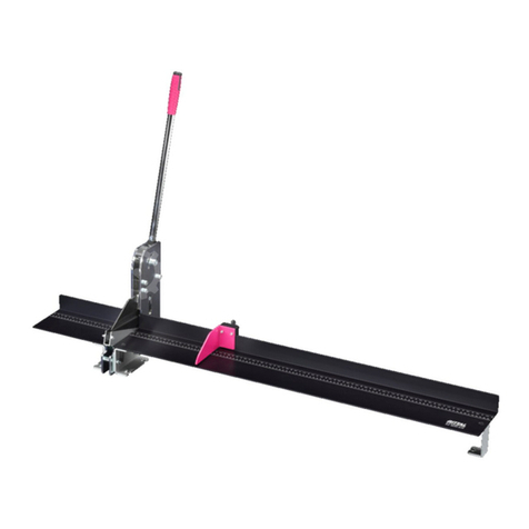
Rittal CW 120-S User manual

Stationary busbar cutting unit CW 120-S
Operating instructions
4055.710

Foreword
EN
2 We reserve the right to make technical modifications. Rittal stationary busbar cutting unit CW 120-S
Foreword
Dear Customer,
We thank you for choosing our Rittal product. Read these operating instructions
carefully before using your new unit for the first time and retain them together
with the supplied Product Control Card so they can be consulted when required.
We wish you every success.
Kind regards
Rittal GmbH & Co. KG
Rittal GmbH & Co. KG
Auf dem Stützelberg
35745 Herborn
Germany
Phone: +49(0)2772 505-0
Fax: +49(0)2772 505-2319
E-mail: [email protected]
www.rittal.com
We are always happy to answer any technical questions regarding our entire
range of products.

Rittal stationary busbar cutting unit CW 120-S We reserve the right to make technical modifications. 3
Contents
EN
Contents
1 CE labelling ...................................................................... 4
2 Safety instructions ............................................................ 4
2.1 Symbols in these operating instructions .............................................. 4
2.2 Symbols on the unit ............................................................................ 4
2.3 General safety instructions .................................................................. 4
2.4 Personal protective equipment............................................................ 5
2.5 Residual risks when using the unit ...................................................... 6
3 Proper usage ................................................................... 6
4 Technical specifications .................................................... 6
5 Available accessories ....................................................... 7
6 Unit description ................................................................ 7
7 Commissioning ................................................................ 8
8 Cutting busbars ............................................................. 10
9 Replacing the cutting blade ............................................ 12
10 Maintenance and inspection ........................................... 13
11 Dismantling and disposal ............................................... 15
12 Contacts ........................................................................ 16

1 CE labelling
EN
4 We reserve the right to make technical modifications. Rittal stationary busbar cutting unit CW 120-S
1 CE labelling
Rittal GmbH & Co. KG confirms the conformity of the stationary busbar cutting
unit with machine directive 2006/42/EC and with EMC directive 2014/30/EU. An
appropriate declaration of conformity has been issued. It can be found at the end
of this document, on the Rittal Homepage or accompanies the unit as separate
document.
2 Safety instructions
2.1 Symbols in these operating instructions
The following symbols are used in this documentation:
This symbol indicates an "action point" and shows that you should perform an
operation or work step.
2.2 Symbols on the unit
The following symbols are attached to the unit.
2.3 General safety instructions
When working with high-pressure hydraulic units, improper handling and/or poor
maintenance can damage the unit and cause severe injuries. Consequently, ob-
serve all the following safety instructions and contact our service team should
you have any questions.
Warning!
A hazardous situation which may lead to death or serious in-
jury if the instructions are not followed.
Caution!
Hazardous situation which may lead to (minor) injuries if the
instructions are not followed.
Note:
Important notices and indication of situations which may result in
material damage.
Warning of laser radiation.
Risk of being crushed or cut by moving unit components.
Observe the operating instructions.
Wear safety goggles.

Rittal stationary busbar cutting unit CW 120-S We reserve the right to make technical modifications. 5
2 Safety instructions
EN
Caution…
– … when handling hydraulic oil. The oil can become very hot after longer oper-
ation. There is a risk of injury!
– To extend the service life of the unit, the hydraulic cylinder should not travel to
the limit stop under full pressure.
– Risk of environmental contamination! Collect any escaped hydraulic oil and
prevent it from entering the sewer system or the surface and ground water.
Always…
– … machine busbars made of copper or aluminium.
– … position busbars centred and perpendicular in the unit.
– … remove objects and foreign bodies from the work area.
– … observe the maximum permitted dimensions of the workpieces.
– … inspect electrical and hydraulic connection lines for damage before deploy-
ing the unit.
– … use the prescribed hydraulic pump.
– … ensure the secure footing of the unit.
– … observe the information contained in the operating instructions.
– … instruct new users in the safe use of the unit.
– … wear safety goggles when working with the unit.
– … observe the local, country-specific regulations.
– … store and deploy the unit in dry and well ventilated spaces.
Never…
– … deploy the unit when parts are damaged or missing.
– … make any changes to the unit or remove the warning signs.
– … reach in the work area of the blade.
– … look intentionally and directly at the laser light.
– … open couplings under pressure.
– … apply pressure to unconnected hose couplings.
– … exceed the maximum operating pressure.
– … operate the unit unattended.
– … subject the unit to corrosive materials.
– … deploy the unit unless the operating instructions have been read and under-
stood completely.
– … store or operate the unit at temperatures above 45 °C (113 °F).
– … deploy the unit in an explosion risk area.
2.4 Personal protective equipment
The operating and maintenance personnel must always wear personal protective
equipment when working on the unit. The personal protective equipment com-
prises at least the following components:
– Safety work shoes: for all work on the unit
– Safety goggles: for all work on the unit
– Gloves: for loading and unloading the unit

3 Proper usage
EN
6 We reserve the right to make technical modifications. Rittal stationary busbar cutting unit CW 120-S
2.5 Residual risks when using the unit
There is danger that during operation a hydraulic hose bursts or a screw fasten-
ing leaks. This means oil can escape at high pressure.
Always wear your personal protective equipment for all work performed on the
unit (see section 2.4 "Personal protective equipment").
There is the danger that small particles are ejected at high speed from the ma-
chining area (e.g. because of tool breakage).
Always wear your personal protective equipment for all work performed on the
unit (see section 2.4 "Personal protective equipment").
If the unit machines busbars made of an impermissible material or from an ex-
cessively thick material, there is the risk of the tools becoming damaged and tool
parts splitting off.
Perform machining on materials only in accordance with the proper usage (see
section 3 "Proper usage") and the technical specifications (see section 4
"Technical specifications").
3 Proper usage
The "stationary busbar cutting unit CW 120-S" (Model No. 4055.710) is a single-
acting high-pressure hydraulic unit for clean cutting copper or aluminium bars
with a maximum width of 120 mm and a maximum height of 12 mm. The unit is
not suitable for cutting structural steels or tool steels. The electro-hydraulic pump
(Model No. 4055.720) with the associated foot-operated switch (Model No.
4055.712) must be used as the drive for the "stationary busbar cutting unit".
4 Technical specifications
Technical specifications
Model No. and designation 4055.710 stationary busbar cutting unit
CW 120-S
Max. pressure 700 bar (10150 psi)
Max. cutting force 230 kN (52200 lbs)
Max. delivery rate 1.95 l/min (0.5 gal/min)
Permissible materialsCopper,aluminium
Max. busbar width 120 mm (4.72")
Max. busbar height 12 mm (0.47")
Laser (line laser) 4.0 mW, Class 1 laser; MTBF>10,000 h
Weight 20.5 kg (40 lbs)
Permissible hydraulic pump Electro-hydraulic pump (Model No. 4055.720)
Tab. 1: Technical specifications

Rittal stationary busbar cutting unit CW 120-S We reserve the right to make technical modifications. 7
5 Available accessories
EN
5 Available accessories
6 Unit description
The "stationary busbar cutting unit" is equipped with a high-performance single-
acting hydraulic cylinder (9) that achieves a cutting force of approximately
23 tons for a maximum pressure of 700 bar.
Fig. 1: Front and rear view
Key
1 Emergency stop switch
2 Connection socket (7-pin) for the control cable
3 Connection for hydraulic hose
4 Retainer with ball bearings
5 Supporting table
6 Side guide plates
7 Locking lever for retainer
8 Clamping screws for retainer
9 High-pressure hydraulic cylinder
10 Connection socket (4-pin) for the foot-operated switch
11 Holes for fastening to the work table
12 Cutter bar with integrated line laser
13 Blade
14 ON/OFF switch for laser
The cutting force is transferred uniformly via the cutter bar (12) to a replaceable
blade (13).
The single-pedal foot-operated safety switch is connected with the cutting unit
via the 4-pin socket (10). In dangerous situations, an additional emergency stop
switch (1) can stop the pump immediately and return the blade to its initial posi-
tion. The combination of supporting table (5), side guide plates (6) and retainers
(4) ensures a reliable, perpendicular guiding of the busbars. The clamping screws
Available accessories Model No.
Electro-hydraulic pump 4055.720
Foot-operated switch 4055.712
Support rollers for busbars 4055.714
Tab. 2: Available accessories

7 Commissioning
EN
8 We reserve the right to make technical modifications. Rittal stationary busbar cutting unit CW 120-S
(8) set the height of the retainers that are fixed at the required position with the
locking levers (7).
A line laser integrated in the cutter bar (12) simplifies the exact positioning of the
busbar. The four holes (11) in the frame can be used for the fixed mounting of
the unit on a table or workshop trolley.
Fig. 2: Dimensions
7 Commissioning
You receive a fully assembled "stationary busbar cutting unit" as well as detailed
operating instructions.
On receiving the goods, check them for possible transport damage and the
delivery for completeness.
In the event of problems, contact the manufacturer or your vendor without de-
lay.
In any case, read the complete operating instructions as well as all supplied
documents before commissioning.
Wear your personal protective equipment, in particular gloves and safety work
shoes, also for the transport and installation of the unit (see section 2.4 "Per-
sonal protective equipment").
Ensure that the surface on which the unit is placed is flat and sufficiently stable.
Inspect the hydraulic hose and the control cable for crushing and any other
damage. Never use damaged hydraulic supply lines or electrical supply cables.
Inspect the mains cable and plug of the hydraulic pump for damage. Do not
use the electro-hydraulic pump should there be any damage!
Place the unit secure and stable to ensure a safe positioning of the unit.
Caution!
When recommissioning the unit, there is the risk that incor-
rect storage or missing corrosion protection can block unit
components and so cause dangers.
Before recommissioning, ensure the smooth running of all
components and the correct function of all safety equip-
ment (see section 10 "Maintenance and inspection").
Note:
The hydraulic hose and the electrical control cable for the unit are
supplied as set in a stable safety protection tube. As supplied, the
hydraulic hose is filled with hydraulic oil HLP46.

Rittal stationary busbar cutting unit CW 120-S We reserve the right to make technical modifications. 9
7 Commissioning
EN
Connect the hydraulic hose to the hydraulic connection (fig. 1, 3) and the elec-
trical control cable to the electrical connection (fig. 1, 2) of the unit.
Then insert the supply cable of the foot-operated switch in the 4-pole connec-
tor (fig. 1, 10).
Before the first use, the sealing screw plug (black) at the tank opening must be
replaced with the air permeable ventilation screw (orange) so that air can flow
into the oil tank during work.
Fig. 3: Replacing the screw plug or ventilation screw (example illustration)
Turn the mains switch of the hydraulic pump to the "I" position to place the
pump in ready mode.
Note:
Rittal recommends that the unit is fastened using the four holes in
the frame on a worktable or workbench.
Caution!
If the unit is operated with a non-approved pump, there is
risk of injury caused by bursting components of the hydraulic
circuit.
Ensure that only the electro-hydraulic pump, in conjunc-
tion with the unit, as specified in the technical specifica-
tions is deployed.
Note:
There is risk of hydraulic oil escaping in the event of a defective valve
or when the hydraulic hose is disconnected under pressure.
Ensure that the hydraulic system is pressure-free before discon-
necting or reinserting the hydraulic hose.
Note:
To prevent hydraulic oil from escaping, the sealing screw plug must
be reinserted in the tank opening for subsequent transport of the
unit.
Screw the sealing screw plug into the thread at the front of the elec-
tro-hydraulic pump to ensure quick and safe access when required.
Note:
Observe the details in the operating instructions of the electro-hy-
draulic pump.

8 Cutting busbars
EN
10 We reserve the right to make technical modifications. Rittal stationary busbar cutting unit CW 120-S
After triggering an emergency stop:
Turn the emergency stop switch slightly so that it returns to its initial position.
The pump is returned to ready mode. It can then be reactivated by actuating
the foot pedal.
If the emergency stop was activated via the foot-operated switch: release the
foot-operated switch by pressing the blue silicone cover at the side (see fig. 4).
Fig. 4: Releasing the foot-operated switch
8 Cutting busbars
Loosen the clamping levers on the side guide plates (fig. 1, 6) of the supporting
table and set the guide plates to the width of the busbar.
Warning!
If a dangerous situation occurs when working with the unit,
stop all dangerous movements of the unit without delay.
In a dangerous situation, press the red emergency stop
switch (fig. 1, 1) on the unit to stop the operation!
As an alternative, press the foot-operated switch beyond
the first pressure point. This also causes the work opera-
tion to stop immediately.
Note:
The electro-hydraulic pump is equipped with an emergency stop
power circuit that is activated by the emergency stop switch of the
connected unit to stop the motor immediately and to deactivate the
integrated magnetic valve.
Note:
To extend the service life of the laser, it should be switched off for
longer machining pauses (> 10-15 minutes).
Warning!
When cutting busbars, the blade can be a risk for cutting or
crushing parts of the body.
Ensure that nobody intervenes in the cutting area, in par-
ticular, after starting a cutting operation.
In a dangerous situation, press the red emergency stop
switch on the unit or alternatively the foot-operated switch
beyond the first pressure point to stop the operation!

Rittal stationary busbar cutting unit CW 120-S We reserve the right to make technical modifications. 11
8 Cutting busbars
EN
To ensure centred guiding of the workpiece below the cutting blade, always
adjust both guide plates.
This is essential for an even cut.
Mark the desired workpiece length centred on the busbar.
Now introduce the busbar from the side of the support roller (fig. 1, 5) starting
in the cutting unit.
Loosen the clamping screws (fig. 1, 8) of the two retainers and set them to the
material thickness of the workpiece.
The correct setting of the guide plates and retainers ensures a better cutting
result.
Actuate the switch for the laser (fig. 1, 14) to switch on the line laser.
Now push the busbar through the cutting unit until the length marking is locat-
ed exactly below the red laser line.
The workpiece with the correct length results on the side without the support-
ing table.
Press the foot-operated switch to the first pressure point (foot pedal pressed
approximately half the distance, corresponds to a force of approx. 20 kg) to
start the cutting operation.
The hydraulic pump is activated and feeds oil to the tool.
After completing the cutting operation, release the pressure from the foot-op-
erated switch to deactivate the pump.
The hydraulic oil now flows from the cutting unit back to the oil tank of the
pump. The blade travels back to its initial position.
To switch off the pump, turn the mains switch to the "0" position.
Note:
The support rollers available as an accessory can also be used.
They must be adjusted to the height of the cutting unit, and permit
a fast and easy machining of the busbars.
Warning!
When cutting busbars, there is the danger that small parti-
cles are ejected at high speed from the machining area.
Always wear your personal protective equipment for all
work performed on the unit (see section 2.4 "Personal pro-
tective equipment").
Note:
The unit housing does not have any switch for ending the cutting
operation. To protect the unit and the hydraulic pump, we recom-
mend that the cutting operation is ended immediately after separat-
ing the busbar. To extend the service life of the laser, it should be
switched off for longer machining pauses (> 10-15 minutes).

9 Replacing the cutting blade
EN
12 We reserve the right to make technical modifications. Rittal stationary busbar cutting unit CW 120-S
9 Replacing the cutting blade
Place the unit without material securely on the table.
Fig. 5: Blade in the lower position
Activate the hydraulic pump and allow the blade to travel down until only a
small curvature (1) can be seen between the blade and the counter cutter.
Switch off the hydraulic pump and immediately disconnect the hydraulic cou-
pling (2) at the cutting unit so the cutter bar remains at the bottom position.
Fig. 6: Dismantling the retainers
Dismantle the two retainers (3) and the side protective inspection window (4).
Caution!
When replacing the cutting blade, there is the risk of injury
caused by sharp edges.
Ensure that the blade replacement is performed by appro-
priately authorised persons.
Wear your personal protective equipment when replacing
the cutting blade (see section 2.4 "Personal protective
equipment").

Rittal stationary busbar cutting unit CW 120-S We reserve the right to make technical modifications. 13
10 Maintenance and inspection
EN
Fig. 7: Loosen the fastening screws
Now loosen the two M8 screws (5) on the side of the cutter bar.
Before removing the screws, secure the blade so it cannot fall.
Fig. 8: Removing the blade
Finally, remove the blade at the bottom of the cutting unit (6). Take care, the
blade is sharp.
Installing the new blade:
Insert the new blade from below and push upwards to the cutter bar.
Screw in the two M8 screws (5) from the side with 15 – 20 Nm torque.
Finally, screw on the retainers (3) and the protective inspection window (4), and
reconnect the hydraulic hose.
10 Maintenance and inspection
The user is obliged to maintain and service the busbar cutting unit in accordance
with the details in the operating instructions and in accordance with the country-
specific standards and regulations.
The maintenance intervals are classified in accordance with the recommended
frequency.

10 Maintenance and inspection
EN
14 We reserve the right to make technical modifications. Rittal stationary busbar cutting unit CW 120-S
Before every use…
… Visually inspect the complete unit, hydraulic pump and hoses as well as the
foot-operated switch for damage.
… Check all electrical and hydraulic connection lines for damage.
… Check the correct, secure attachment of the hydraulic couplings.
… Check the correct functioning of the foot-operated switch.
Weekly…
… Clean the complete unit. To prevent damage to the safety instructions on
the unit, do not use any aggressive cleaning agents.
… Clean the blade and the counter cutters by blasting with dry compressed
air.
… Grease the blade and counter cutters externally lightly with universal grease.
… Check the correct functioning of the safety shutdown on the foot-operated
switch.
… Check the correct functioning of the emergency stop switch of the unit for
the activated pump.
Monthly…
… Visually inspect the blade and counter cutters for defects or breakages, and
replace when necessary.
… Check the markings and warning signs on the unit for readability and dam-
age, and replace if necessary (see section 2.2 "Symbols on the unit").
Every 6 years…
… Replace the hydraulic hose.
Maintenance, inspections and repairs must be performed by qualified electri-
cians in accordance with the regulations valid in the associated country.
Caution!
When a unit has been switched on, there is the risk of it start-
ing, such as for inadvertent actuation of the foot-operated
switch with the associated risk of injury in the area of unit
components.
Before any servicing and repair work, ensure that the unit
mains plug of the connected hydraulic pump has been dis-
connected to prevent inadvertent starting.
Note:
An inadequate protective film or an excessively long downtime of
the unit can lead to corrosion and so impair the function of the com-
ponents.
Warning!
There is risk of injury with defective safety equipment.
If the inspection of the safety shutdown equipment deter-
mined that they do not stop the unit, bring the unit to stand-
still immediately.
Repair the safety shutdown equipment without delay.
Operate the unit again only after the repair work has been
completed.

Rittal stationary busbar cutting unit CW 120-S We reserve the right to make technical modifications. 15
11 Dismantling and disposal
EN
11 Dismantling and disposal
Wear your personal protective equipment, in particular gloves and safety work
shoes, also for the dismantling and disposal of the unit (see section 2.4 "Per-
sonal protective equipment").
To switch off the hydraulic pump, turn the mains switch to the "0" position.
Remove the ventilation screw and close the tank opening with the screw plug
to prevent hydraulic fluid from escaping.
Disconnect the supply cable of the foot-operated switch from the 4-pin con-
nection.
Disconnect the hydraulic hose from the hydraulic connection and the electrical
control cable from the electrical connection of the unit.
When the hydraulic pump is switched off or the hydraulic system is pressure-
free, the hydraulic hose can be disconnected safely without any hydraulic fluid
escaping.
The "stationary busbar cutting unit" must be properly disposed of or recycled in
accordance with the country-specific regulations.

12 Contacts
EN
16 We reserve the right to make technical modifications. Rittal stationary busbar cutting unit CW 120-S
12 Contacts
For technical queries, please contact:
– Phone: +49(0)2772 505-9052
– Homepage: www.rittal.com
For sales or service requests, please contact your local Rittal organisation
which can be found at www.rittal.com/contact.

Rittal stationary busbar cutting unit CW 120-S We reserve the right to make technical modifications. 17
Notes

Notes
18 We reserve the right to make technical modifications. Rittal stationary busbar cutting unit CW 120-S

Rittal stationary busbar cutting unit CW 120-S We reserve the right to make technical modifications. 19
Notes

◾Enclosures
◾ Power Distribution
◾ Climate Control
◾ IT Infrastructure
◾ Software & Services
You can find the contact details of all
Rittal companies throughout the world here.
www.rittal.com/contact
RITTAL GmbH & Co. KG
Postfach 1662 · D-35726 Herborn
Phone +49(0)2772 505-0 · Fax +49(0)2772 505-2319
11.2018 / D-0100-00000011 Rev. 01
This manual suits for next models
1
Table of contents
Other Rittal Cutter manuals
Popular Cutter manuals by other brands

Mafell
Mafell KSS 80 Ec/370 Original operating instructions and spare parts list

Cembre
Cembre TC085 Operation and maintenance manual
Makita
Makita DCS550 instruction manual

Cricut
Cricut Joy Xtra JCTR201C user guide

Silca
Silca POKER PRO operating manual
Hubbell
Hubbell ANDERSON BP18CC129ACSR SAFETY OPERATING & MAINTENANCE INSTRUCTIONS
