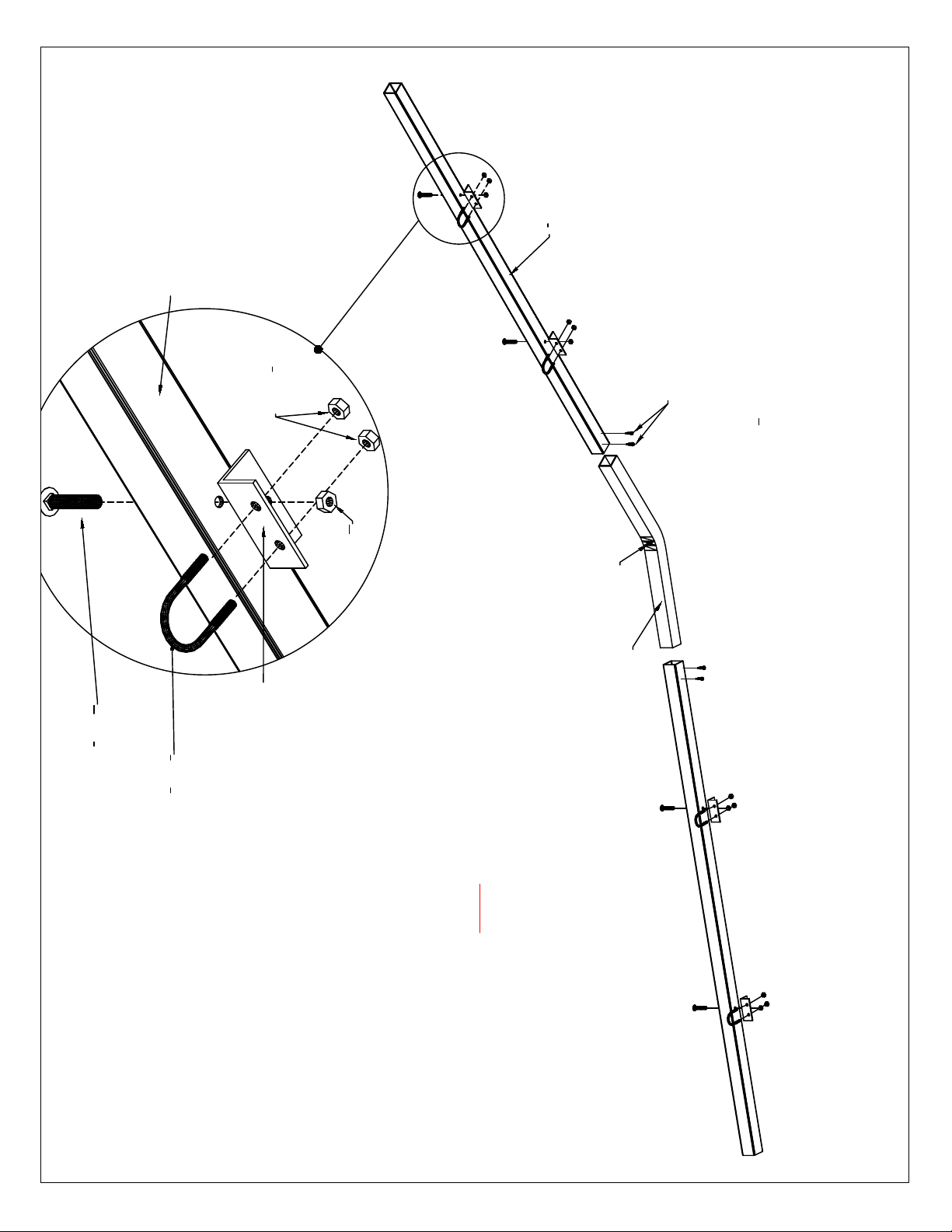
Sidewall & Roof Purlin
Sidewall Horizontal Purlin (2'' x 2'' square tubing) will need to be cut
into 70'' pieces, this should be the distance between each leg.
Before cutting, measure from inside to inside of each leg to make
certain that this is your measurement.
5' sidewall = 29"
6' sidewall = 35''
8' sidewall = 47"
2'' x 2'' sidewall
horizontal purlin
side groundrail
legs
1. Depending on sidewall height ordered, measuring up from the top of
the groundrail place purlin at 29'' for 5'-0'' sides or 47'' for 8'-0'' sides.
2. Attach purlin to legs using 3'' x 3'' L brackets & #14 tek screws see
detail B.
leg
purlin
#14 tek
screws
3x3
L bracket
2''x 2'' sidewall
horizontal
purlin
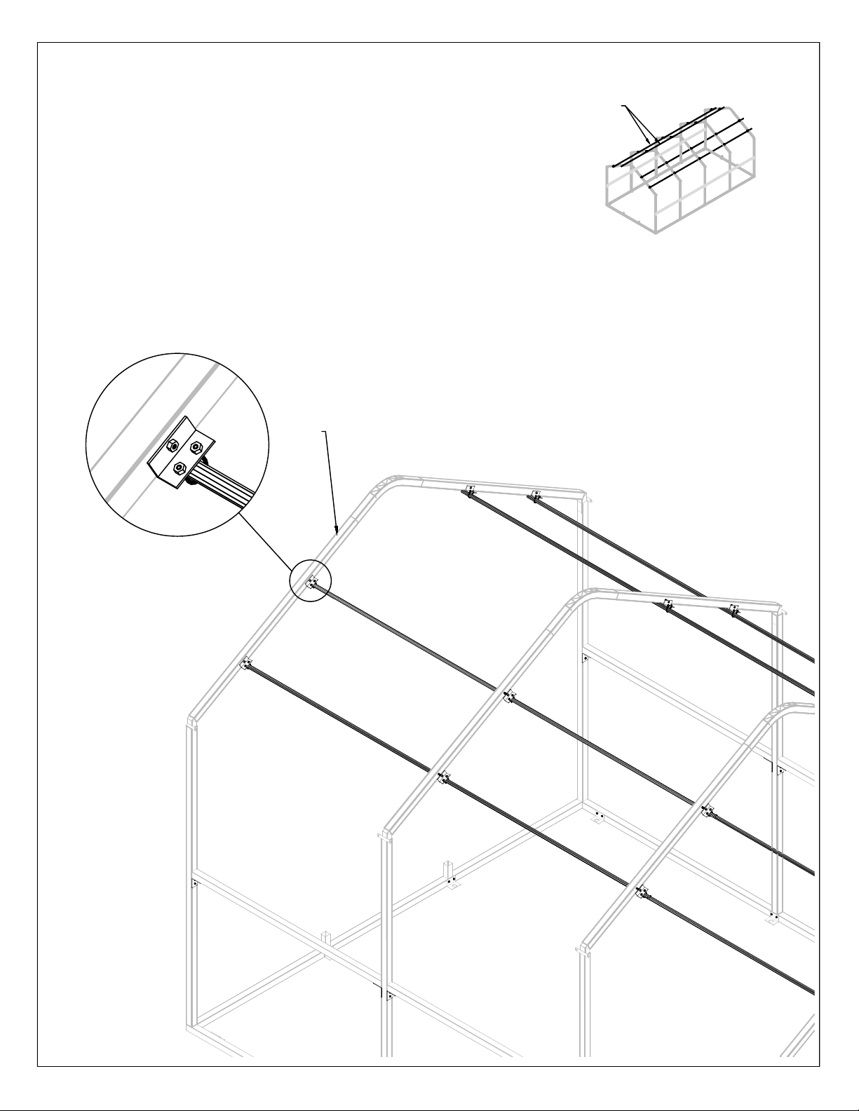
roof
purlin
detail B
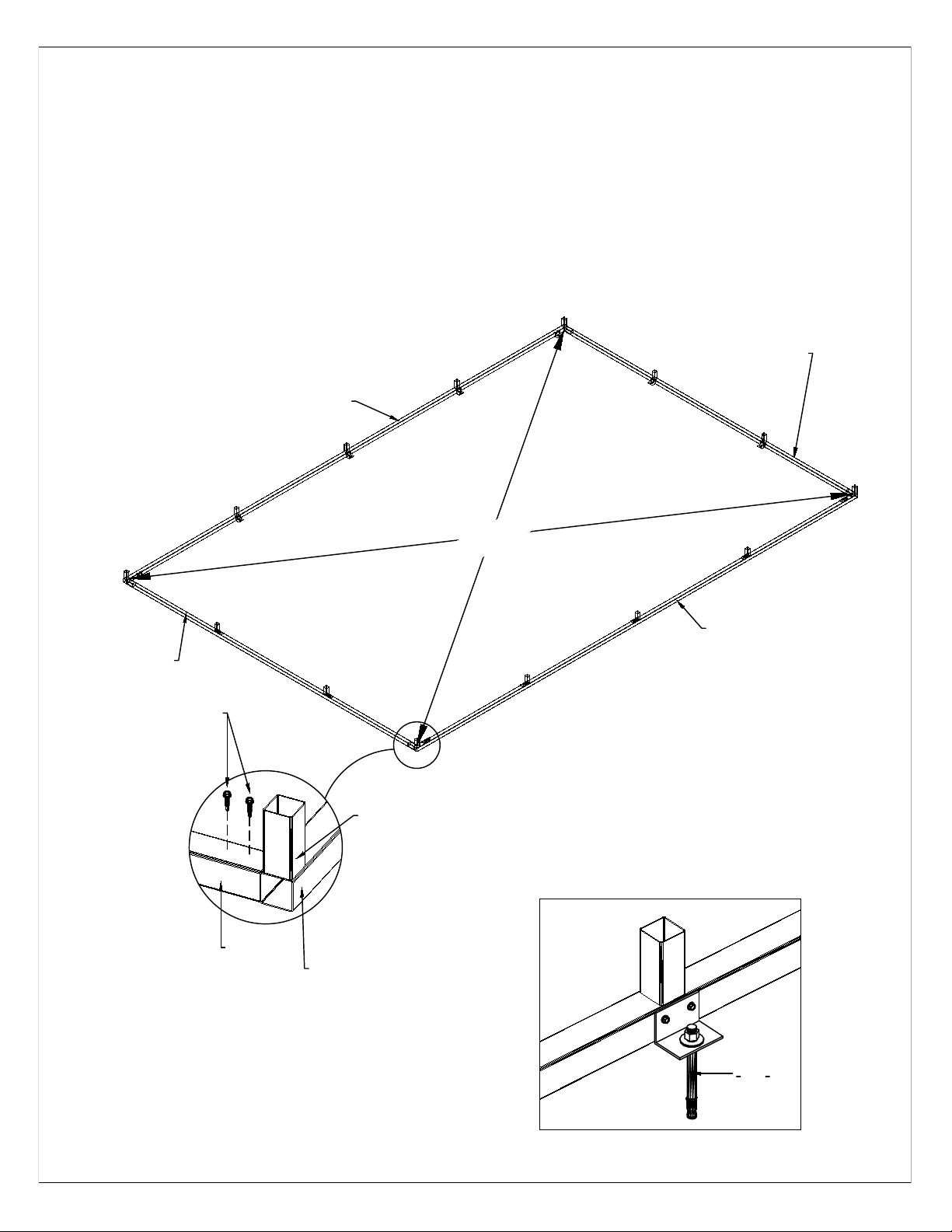
PREPARING of ROOF PURLIN
Identify 1 3/8" x 12'-5'' purlin with swedge.
1. connect the appropriate number of purlin
together to equal the length of your
greenhouse see detail C. You may have
excess, you will cut it off at a later time.
2. Next, lay the connected purlin, on the
ground flush with the end of the side
groundrail see overhead view of corner.
3. Make a mark 2'' from the end - this
represents the width of the leg on the
purlin. Then move down and mark one side
of the intermediate leg (on the purlin) and
then the other side of the leg (on the purlin)
4. Repeat this process for the length of the
structure and all runs of purlin.
Overhead View
of Corner
line = purlin flush
w/ end of
groundrail
line-up mark
for rafter
purlin
detail C.
purlin (male end)
purlin (female end)
tek screw
70''
groundrail
see
detail C.
roof
purlin