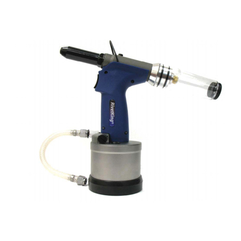
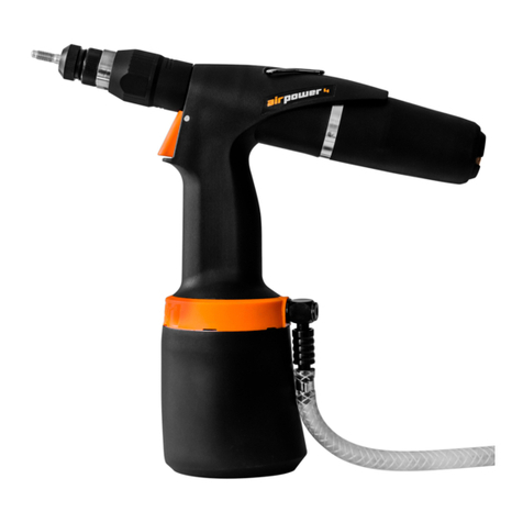
Rivet King RK-986 User manual

INSTRUCTION MANUAL
RK-986
TOOLS FOR BLIND RIVETS, STRUCTURAL
RIVET NUTS AND LOCKBOLTS
PNEUMATIC RIVETING TOOL
EN

RK-986
www.rivet.com
13
EN
INDEX
13
13
13
13
13
14
14
14
14
18
18
19
19
19
19
20
21
21
21
1. IDENTIFICATION
2. DESCRIPTION
3. VIBRATION AND NOISE LEVEL
4. ELECTROMAGNETIC ENVIRONMENT
5. SAFETY PRECAUTIONS AND WARNINGS
6. STORAGE
7. SPECIFICATIONS
8. CONTENTS
9. KITS
10. AIR SUPPLY AND PRESSURE REGULATOR
11. INSIDE THE MACHINE
12. CHECKS BEFORE USING THE MACHINE
13. PREPARATION AND OPERATION
14. MAINTENANCE
15. PURGING OR PRIMING MANNER 1
16. PURGING OR PRIMING MANNER 2
17. ASSISTANCE
18. GUARANTEE
19. MOST COMMON PROBLEMS
20. BREAKDOWN 85
1. IDENTIFICATION
The RIVETKING RK-986 riveting machine is
identified by a nameplate on the outside with a
serial number, RIVETKING logo, address, website
and CE-UK mark.
2. DESCRIPTION
The RK-986 riveting machine is a tool designed to
set structural rivets, collar bolts and Structural
rivets. Ideal for assembly lines.
This is a riveting machine with a lightweight gun in
painted aluminum for effortless operation, which
is connected with a hose to a wheeled control
unit. Inside the control unit are the drive
valve, the air filtering system, the pressure
regulation, the oil and filter tank and two pistons,
one for traction force and the other for recovery
force, the latter is essential for the machine’s
recovery.
3. VIBRATION AND NOISE LEVEL
The continuous sound pressure level recorded in
the workplace does not exceed 80 dB, as this is a
tool designed to work at low noise levels for the
safety of the operator.
If all instructions are followed, this is a riveting
machine that does not generate any vibrations
that could cause harm to the operator.
4. ELECTROMAGNETIC ENVIRONMENT
The RK-986 riveting machine is approved to work
in industrial electromagnetic environments, it is
within the Emission and Immunity limits under the
following standards: General Emission Standard
-Part 2 Industrial Environment (2007) and
the General Immunity Standard - Part 2 of the
Industrial Environment (2006) of EN 61000-6-4
Electromagnetic Compatibility (EMC) standard.
5. SAFETY PRECAUTIONS AND
WARNINGS
Read the entire instruction manual carefully
before installing, operating or repairing this
tool. Keep this instruction manual near the
tool at all times.
•This manual has been written so that
operators can operate the machine and carry out
maintenance work, but they must not carry out
repair work, as only RIVETKING USA authorized
technicians can carry out these more technical
tasks.
•RIVETKING offers you training and qualified
personnel.
Suitable clothing must be worn
to avoid entanglement with the
tool, protective goggles for the
operator and bystanders, and
gloves.
•Any modifications made to the tool by
the customer its the sole responsibility of
the same. RIVETKING is available to give any
suggestions required before the customer makes
modifications.
•Damage caused by transport or mishandling is
not covered by RIVETKING’s warranty and shall be
borne by the customer.
14
BRALO
EN
•Only kits supplied by RIVETKING should be
used for the brand rivets.
•Disconnect the air supply before installing or
adjusting the kits.
•When disconnecting the air hose, make sure
that there is no pressure.
•The user must maintain the riveting machine in
a safe working condition and in a clean working
area.
•The machine must be operated at all times in
accordance with current Health and Safety
legislation.
•Take care not to operate the riveting machine
when it is pointed at any person or at the
operator.
•The tool should not be pulled by the hose or gun
but by the control unit, taking the hand off the
trigger to avoid trigger actuation. Keep the hose
away from heat sources or sharp objects.
•Remember that the air pressure must not
exceed 7 bar and the air inlet must not exceed 8
bar.
•Care should be taken not to spill hydraulic oil and
clean up thoroughly with water and alkaline soap if
spilled on the skin.
•Remember to use ISO VG 32 oil for
maintenance work.
6. STORAGE
For the correct storage of the tool if it is not going
to be used for a period of time, possible impacts,
places of tension, thermal variations, humidity and
corrosive substances must be taken into account.
7. SPECIFICATIONS
Weight 28 Kg
Gun weight 1,7 kg
Dimensions of the
Control Unit (mm) 495 x 295 x 250
Gun dimensions (mm) 320x 170
Air pressure (bar) 6-7 bar
Maximum power at 6 bar 40000N
Piston travel (mm) 32 mm
Hydraulic oil ISO VG 32
Oil pressure at 6 bar 300 bar.
Intensication ratio 1:50
8. CONTENTS
Inside the packaging you will nd the instruction
manual and a bag with the air connection and
the key to open the control unit.
The customer shall purchase the necessary
consumables according to his needs.
9. KITS
REFERENCE KIT
RK986-2020
RK986-2010 KIT RIVETING Ø6,5 TIGERBOLT/MONOBOLT
KIT RIVETING Ø9,7 TIGERBOLT/MONOBOLT
RK986-2021*
RK986-2022*
05HT00B0800
KIT RIVETING Ø4,8 MULTIGRIP COLLAR BOLT
KIT RIVETING Ø6,4 MULTIGRIP COLLAR BOLT
RIVETING Ø8,0 MULTIGRIP COLLAR BOLT
RK986-2023*
RK986-2024*
RK986-2025
RK986-2026
KIT RIVETING Ø4,8 FIXED GRIP COLLAR BOLT
KIT RIVETING Ø6,4FIXED GRIP COLLAR BOLT
KIT RIVETING Ø8,0 FIXED GRIP COLLAR BOLT
KIT RIVETING Ø10,0 FIXED GRIP COLLAR BOLT
RK986-2029
RK986-2027
RK986-2028
KIT RIVETING Ø4,8 BOM RIVET
KIT RIVETING Ø6,4 BOM RIVET
KIT RIVETING Ø8,0 BOM RIVET
* These kits need the adapter 05BM3001023

RK-986
www.rivet.com
15
EN
COMPLETE KIT FOR BRALO STRUCTURAL RIVETS Ø 9.7 mm
Nº REFERENCE DESCRIPTION
1RK986-2001 NOSEPIECE Ø9,7 STRUCTURAL
2RK986-2002 NOSEPIECE HOLDER
ARK986-2003 NOSEPIECE HOLDER NUT
4RK986-2004 JAW HOLDER
5RK986-2005 JAWS Ø9,7 STRUCTURAL
6RK986-2006 JAW PUSHER
7RK986-2007 PUSHER SPRING
8RK986-2008 DRIVER GUIDE
BRK986-2009 NOSEPIECE HOLDER STOP
RK986-2010 KIT Ø9,7 STRUCTURAL
To unscrew the 9.7 mm structural
full nosepiece head use a 17 mm
wrench.
COMPLETE KIT FOR BRALO STRUCTURAL RIVETS Ø 6.5 mm
Nº REFERENCE DESCRIPTION
105BM0000983 NOSEPIECE Ø6,5 STRUCTURAL
2RK986-2012 NOSEPIECE HOLDER Ø6,5 STRUCTURAL
2A RK986-2013 LONG NOSEPIECE HOLDER Ø6,5 STRUCTURAL
A* RK986-2003 NOSEPIECE HOLDER NUT
4RK986-2014 JAW HOLDER Ø6,5 STRUCTURAL
5RK986-1003 JAWS Ø6,5 STRUCTURAL
6RK986-2016 JAW PUSHER Ø6,5 STRUCTURAL
6A RK986-2017 LONG STEM TUBE GUIDE Ø6,5 STRUCTURAL
705BNT000355 JAWS PUSHER SPRING
8RK986-2018 MANDREL TUBE GUIDE Ø6,5 STRUCTURAL
8A RK986-2019 DRIVER GUIDE Ø6,5 STRUCTURAL
B* RK986-2009 NOSEPIECE HOLDER STOP
RK986-2020 KIT Ø6,5 STRUCTURAL
05BM3002011 LONG KIT Ø6,5 STRUCTURAL
1
2
4
5
6
78
14567
6A
22A 8 8A
AB
AB
* Parts A and B come
installed on the machine.

16
BRALO
EN
Nº DESCRIPTION UNILOCK
Ø4,8 BRALOCK
Ø4,8 UNILOCK
Ø6,4 BRALOCK
Ø6,4
1HOLDER AND NOSEPIECE ASSEMBLY RK986-2023-1 RK986-2021-1 05BM3002024-1 05BM3002022-1
2 NOSEPIECE RK986-2023-2 RK986-2021-2 05BM3002024-2 05BM3002022-2
3NOSEPIECE HOLDER RK986-2023-3 RK986-2021-3 RK986-2024-3 RK986-2022-3
4 JAW HOLDER RK986-2023-4 RK986-2021-4 RK986-2024-4 RK986-2022-4
5JAWS SET RK986-2023-5 RK986-2021-5 RK986-2024-5 RK986-2022-5
6 JAW HOLDER EXTENSION RK986-2023-6 RK986-2021-6 RK986-2024-6 RK986-2022-6
7 GASKET RK986-2023-7 RK986-2021-7 RK986-2024-7 RK986-2022-7
8* NUT RK986-2033 RK986-2033 RK986-2033 RK986-2033
9* SLEEVE RK986-2038 RK986-2038 RK986-2038 RK986-2038
10* NOSEPIECE STOP RK986-2039 RK986-2039 RK986-2039 RK986-2039
KITS RK986-2023 RK986-2021 RK986-2024 05BM002022
COMPLETE KIT FOR FIXED GRIP & MULTIGRIP COLLAR BOLTS FOR Ø 10,0
234
1
Nº DESCRIPTION FIXED GRIP
COLLAR BOLTS Ø8,0 MULTIGRIP
COLLARBOLTS Ø8,0 FIXED GRIP
COLLAR BOLTS
Ø10,0
1 NOSEPIECE RK986-2025-1 RK986-B0801 RK986-026-1
2JAWS HOLDER RK986-2025-2 RK986-B0802 RK986-2026-2
3 JAW HOLDER SET RK986-2025-3 RK986-B0803 RK986-2026-3
4 JAW HOLDER EXTENSION RK986-2025-4 RK986-B0804 RK986-2026-4
5SPACER WASHER RK986-2025-5 RK986-B0805
A*NUT RK986-2003 RK986-2003 RK986-2003
B*NOSEPIECE STOP RK986-2009 RK986-2009 RK986-2009
KIT RK986-2025 RK986-B0800 RK986-2026
2384567
COMPLETE KIT FOR COLLARBOLTS Ø 4,8 AND Ø 6,4 1
9
10
234
15
* Parts 8, 9 and 10 belong to a necessary Kit supplied as an option 05BM3001203
COMPLETE KIT FOR FIXED GRIP & MULTIGRIP COLLAR BOLTS FOR Ø 8,0
* Parts A
and B come
installed on
the machine.
A
A
B
B

RK-986
www.rivet.com
17
BOM RIVET LOCKBOLTS COMPLETE KIT Ø 6,4
123
4
BOM RIVET LOCKBOLTS COMPLETE KIT Ø 8,0
245
3
1
Nº DESCRIPTION BOM RIVET
Ø6,4
1 NOSEPIECE RK986-2027-1
2JAW HOLDER RK986-2027-2
3 JAWS SET RK986-2027-3
4SPACER RK986-2027-4
A* NUT RK986-2009
B* NOSEPIECE STOP RK986-2003
KIT RK986-2027
Nº DESCRIPTION BOM RIVET
Ø8,0
1 NOSEPIECE RK986-2028-1
2JAW HOLDER RK986-2028-2
3EXTENSION RK986-2028-3
4 JAWS SET RK986-2028-4
5 SPACER RK986-2028-5
A* NUT RK986-2009
B* NOSEPIECE STOP RK986-2003
KIT RK986-2028
A
B
A
B
* Parts A and B come installed on the machine.
BOM RIVET LOCKBOLTS COMPLETE KIT Ø 4,8
EN
Nº DESCRIPTION BOM RIVET
Ø4,8
1 NOSEPIECE RK986-2029-1
2JAW HOLDER RK986-2029-2
3 JAWS SET RK986-2029-3
4TRACKER RK986-2029-4
5 SPRING RK986-2029-5
6SLEEVE RK986-2029-6
7JAW HOLDER EXTENSION RK986-2029-7
8* NUT RK986-2033
9* SLEEVE RK986-2038
10* NOSEPIECE STOP RK986-2039
KIT RK986-2029
8
1257
10
3469
* Parts 8, 9 and 10 belong to a necessary
Kit supplied as an option 05BM3001203

18
BRALO
EN
10. AIR SUPPLY AND PRESSURE REGULATOR
This machine is designed to operate with a compressed air supply.
It is necessary to use an air pressure regulator, this ensures a long service life of the machine and
reduces malfunctions to a minimum.
Make sure that the compressed air supply is dry and clean, as moisture and impurities can cause
malfunctions in the machine.
The air must be FILTERED AND OILED for proper operation of the machine.
Make sure that the maximum hose distance from the pressure regulator to the machine is 3 metres.
Hoses shall have a minimum burst strength equal to 30 bar.
The hose should have a diameter greater than 8 mm and use high ow air connections.
Air supply
Bleeding
key Lubricater
3 metres
Air inlet with hose larger than
de más de Ø8 mm
Closed
key
Pressure
regulator
Drying
Filtering
Oil deposit
Pressure
regulation and
air ltering
11. INSIDE THE MACHINE
Hydraulic
outlets
Oil ltering
Pressure gauge
Actuating valve
Recovery piston
Air intake
Traction piston

RK-986
www.rivet.com
19
EN
12. CHECKS BEFORE USING
THE MACHINE
•Check if the machine has been damaged
during transport.
•Make sure that the compressed air hose is
properly connected to the air supply.
•Check the oil level in the tank, it should be
half full.
Please note that the oil cap is blocked during
transport, remove the safety lock to check the
oil level.
For subsequent transfers of the machine, return the
cap to the locked position to prevent spillage.
13. PREPARATION AND OPERATION
•The control unit must always be in a horizontal
position (resting on the wheels).
•Place the appropriate kit.
•Check that the oil level is half full (should be
between the minimum and maximum marks).
•Remove the air from the oil tank by unscrewing
the cap at least 2 turns.
•Connect the machine to the air supply.
•Check that the air pressure input is between
6-7 bar.
•The inside of the air inlet hose must be more
than 8 mm in diameter.
•Adjust the pressure with the internal pressure
gauge to 6-7 bar.
•Check that the wires of all connections are not
loose.
•Insert the stem into the nosepiece.
•Insert the rivet into the application with the
rivet head perpendicular. Do not hold the rivet
with your ngers!
•Squeeze the trigger. Make sure that the stem
is ejected.
*The front castor wheels have a safety lock to
prevent unwanted movement of the machine
during use.
14. MAINTENANCE
•To avoid tool failure, maintenance and
cleaning work is recommended:
•Disconnect the air supply.
•Use appropriate personal protection before
cleaning the machine from dust, debris or oil.
•Check the correct tightening of the kits on a
daily basis.
•Check the quality of the hoses, air supply and
possible damage or air leaks.
•Check the oil level in the tank.
•If there is continuous use, check the condition
of the nosepiece, jaws and gun parts.
•Dismantle and clean the nosepiece holders
weekly with a dry cloth.
•Check that the lubricator is connected and that
the pressure regulator is free of dirt.
*Riveting machine components must be
replaced when worn and damaged. The
operator must not carry out repairs to the
machine.
15. PURGING OR PRIMING MANNER 1
1) Have an oil pan to collect excess oil.
2) Disconnect the air supply and turn the oil
deposit cap on the intensier.
3) Fill the deposit with VG 32 Hyspin R oil up to 2
cm (0.8”) from the top of the deposit.
4) Remove the TRACTION bleed screw (A) and
washer (B) from the gun.
5) Connect the machine to the air supply. Do not
point the venting holes at the face of the operator
or surrounding persons.
6) Position the TRACTION bleed screw of the gun
on the oil container.
7) Activate the trigger and the oil will be expelled
from the bleed hole. Release the trigger.
8) Re-activate the trigger and, at the same time,
t screw A and washer B. Then release the
trigger.
*Tank locked, remove safety lock.

20
BRALO
EN
9) Remove the RECOVERY bleed screw (C) and
washer (D) from the gun.
10) Connect the machine to the air supply. Do
not point the venting holes at the face of the
operator or surrounding persons.
11) Activate the trigger and the oil will be
expelled through the RECOVERY bleed hole.
Release the trigger. Fit screw C and washer D
without fully tightening.
12) Pull the trigger several times for a few
seconds to release the oil without air. Activate
the trigger while tightening the RECOVERY screw
with a Hex key. And release the trigger. Tighten
the TRACTION screw.
13) Check the oil deposit and rell if necessary.
16. PURGING OR PRIMING MANNER 2
1) Have an oil pan to collect excess oil.
2) Switch on the air supply.
3) Press the trigger and at the same time, slightly
loosen the TRACTION bleed screw (A) to release
the air bubbles keeping the trigger pressed, when
no more air comes out, tighten the screw A.
4) Repeat this procedure several times, until oil
comes out without air bubbles.
5) In this way the TRACTION circuit is purged,
and the RECOVERY circuit is then purged:
6) Make sure that the oil tank is not empty.
7) Maintain the air supply connected.
8) The RECOVERY bleed screw (C) at the rear of
the gun must be slightly loosened to release the
air bubbles.
9) Tighten the RECOVERY bleed screw when no
more bubbles come out.
10) Activate the trigger several times for a few
seconds to circulate the oil without bubbles.
11) Check the oil deposit and rell if necessary.
12) Check the stroke length at 32 mm to verify
that bleeding has been performed correctly.
RECOVERY BLEED
SCREW (C) RECOVERY BLEED
WASHER (D)
TRACTION BLEED
SCREW (A)
TRACTION BLEED
WASHER (B)

RK-986
www.rivet.com
21
EN
19. MOST COMMON PROBLEMS
PROBLEMS AND CAUSES SOLUTION
SEVERAL TRIGGER PULLS ARE NECESSARY TO SET THE RIVET
Low air pressure. Increase air pressure.
Excessive lubrication at the air inlet Pour oil into the air inlet.
Broken or worn jaws. Replace the jaws.
There is air in the oil or the oil level in the oil tank is low Rell the oil tank.
RIVETER DOES NOT GRIP THE RIVET STEM CORRECTLY
The jaws are broken or dirty. Replace jaws or clean them.
The jaw clamp is loose. Tighten the jaw clamp.
The nosepiece spring is broken or loose. Replace the spring.
The parts have been incorrectly positioned or there is a
wrong part. Identify the wrong parts.
RIVETING MACHINE DOES NOT BREAK THE STEM
Insufcient air pressure. Check air pressure or air leaks.
Stem length is incorrect for the application. Replace the rivet.
There is little oil. Fill the oil tank.
The air outlet is dirty. Clean the air outlet.
THE MACHINE TAKES LONGER TO RIVET
Low air ow Check ow rate and hose.
17. ASSISTANCE
To keep the tool in good condition, it is
recommended to service the tool and
replace worn parts on a regular basis.
Should you require these services or spare
parts, please contact us directly:
INDUSTRIAL RIVET & FASTENER CO
35 MAPLE STREET
NORWOOD, NEW JERSEY 07647
1-800-289-7483
18. GUARANTEE
The warranty is valid for 12 months from the
invoice purchase date.
The guarantee only covers defects in the parts or
their assembly.
Damage to the tool caused by the following
cases is not covered by the warranty:
-Transport.
- Operator usage errors.
- Errors in maintenance work.
- Breakages or failures that are not attributed to
manufacturing defects.
- Normal wear and tear on consumable parts.
The warranty is invalid if tool components
are replaced without authorisation or if worn
parts other than those recommended by the
manufacturer are replaced, which could cause
damage to the tool.
RIVETKING assumes responsibility for
manufacturing defects, but is not liable if the
operator does not follow the instructions given in
this manual. The tool is built according to
the European Directive in force when the
riveting tool is marketed.
Table of contents
Other Rivet King Rivet Tools manuals

Rivet King
Rivet King FreeSet RK-777C-1Q User manual

Rivet King
Rivet King RK-INLINE User manual

Rivet King
Rivet King RK-250 User manual

Rivet King
Rivet King RK-187 User manual

Rivet King
Rivet King RK-59SPS User manual

Rivet King
Rivet King RK21 Operator's manual

Rivet King
Rivet King FreeSet RK-777-1 User manual

Rivet King
Rivet King RK-8000S User manual