kincrome K13272 User manual

K13272
ED1 April 17
AIR NUT
RIVETER
COMPACT
AND
LIGHT
WEIGHT
1219KG
OF TRACTION
POWER
5
MANDRELS
SUITABLE FOR
STAINLESS
STEEL,
ALUMINIUM &
2
YEAR
WARRANTY

1
Table of Contents
Know Your Product...................................................................................................1
General Safety Instructions.....................................................................................2
Additional Safety Instructions..................................................................................3
Assembly...................................................................................................................4-5
Operation...................................................................................................................5-6
Maintenance & Warranty.........................................................................................6-7
Parts Breakdown......................................................................................................7-8
Know your product
1. Air Inlet
2. Trigger
3. Mandrel (M4, M5, M6, M8, M10)
4. Nose Piece
5. Nose Piece Locking Nut
6. Frame Head
7. Manual Mandrel Remover
8. Cylinder
9. Lock Nut
10. Nitto Style Fitting
11a. MultiJaw Spanner (10mm)
11b. MultiJaw Spanner (8mm)
11c. Multi Jaw Spanner (19mm)
11d. MultiJaw Spanner (28mm)
11e. MultiJaw Spanner (14mm)
12. Rear Mandrel Housing
10
12
1
9
2
3
4
67
8
Model No:...................................................................................................................K13272
Description: ...............................................................................................................Semi-Auto Air Nut Riveter
Air Inlet:.....................................................................................................................1/4”
Average Air Consumption:.......................................................................................99 lpm
Traction Power:.........................................................................................................1219kg (2687lb)
Air Pressure (max.):.................................................................................................70-90 PSI
Hose Length (max.):.................................................................................................10m
Hose Diameter (min.):..............................................................................................10mm ID (3/8”)
Tool Length:...............................................................................................................232mm
Tool Stroke: ...............................................................................................................17.3mm
Weight:.......................................................................................................................1.65kg
5
11a
11b11c11d11e

2
General Safety Warnings
Save all warnings and instructions for future reference.
WARNING! Read all safety warnings and all instructions. Failure to follow the warnings and instructions may result
in electric shock, fire and/or serious injury.
1) Work Area
a. Keep the work area clean and well lit. Cluttered benches and dark areas increase the risks of electric shock, fire, and
injury to persons.
b. Keep bystanders, children, and visitors away while operating the tool. Distractions can result in the loss of control of
the tool.
c. Keep children and bystanders away while operating any powered products. Distractions can cause you to lose control.
2) Personal Safety
a. Stay alert. Watch what you are doing and use common sense when operating the tool. Do not use the tool while tired or
under the influence of drugs, alcohol, or medication. A moment of inattention while operating the tool increases the risk of
injury to persons.
b. Dress properly. Do not wear loose clothing or jewellery. Contain long hair. Keep hair, clothing, and gloves away from
moving parts. Loose clothes, jewellery, or long hair increases the risk of injury to persons as a result of being caught in
moving parts.
c. Avoid unintentional starting. Be sure the trigger is not depressed before connecting to the air supply. Do not carry the tool
with your finger on the trigger or connect the tool to the air supply with the trigger on.
d. Remove adjusting keys and wrenches before turning the tool on. A wrench or a key that is left attached to a rotating part of
the tool increases the risk of personal injury.
e. Do not overreach. Keep proper footing and balance at all times. Proper footing and balance enables better control of the
tool in unexpected situations.
f. Use safety equipment. A dust mask, non-skid safety shoes and a hard hat must be used for the applicable conditions. Wear
heavy-duty work gloves during use.
g. Use eyeand hearing protection. Wear ANSI approved safety impact goggles, hearing protection, and heavy-duty work gloves when
using this Riveter. Other people inthe workarea must also wear appropriate ANSI approved safety equipment.
h. Always wear hearing protection when using the tool. Prolonged exposure to high intensity noise can contribute to
hearing loss.
3) Tool Use andCare
a. Use clamps or other practical ways to secure and support the workpiece to a stable platform. Holding the work by hand or
against the body is unstable and can lead to loss of control.
b. Do not force the tool. Use the correct tool for the application. The correct tool will do the job better and safer at the rate for
which the tool is designed.
c. Do not use the tool if the trigger does not turn the tool on or off. Any tool that cannot be controlled with the trigger is
dangerous and must be repaired, by an authorised repair agent.
d. Disconnect the tool from the air source before making any adjustments, changing accessories, or storing the tool. Such
preventative safety measures reduce the risk of starting the tool unintentionally. Turn off and detach the air supply, safely
discharge any residual air pressure, and release the throttle and/or turn the switch to its off position before leaving the
work area.
e. Store idle tool out of the reach of children and do not allow persons unfamiliar with the tool or these instructions to
operate the tool. Tools are dangerous in the hands of untrained users.
f. Maintain the tool with care. A properly maintained tool is easier to control.
g. Check for misalignment or binding of moving parts, breakage of parts, and any other condition that affects the tool’s
operation. If damaged, have the tool serviced before using, at an authorised Kincrome repair agent. Many accidents are
caused by poorly maintained tools.
h. Use only accessories that are identified by the manufacturer for the specific tool model. Use of an accessory not intended
for use with the specific tool model, increases the risk of injury to persons.

3
4) Service
a. Tool service must be performed only by qualified repair personnel.
b. When servicinga tool, use only identical replacement parts. Use only authorized parts.
c. Use only the lubricants specified by the manufacturer.
5) Additional Safety Warnings
a. The warnings and precautions discussed in this manual cannot cover all possible conditions and situations that may
occur. It must be understood by the operator that common sense and caution are factors which cannot be built into this
product, but must be supplied by the operator.
b. Only use with accessories rated to handle the forces exerted by this tool during operation. Other accessories not
designed for the forces generated may break and forcefully launch pieces.
c. Attach all accessories properly to the tool before connecting the air supply. A loose accessory may detach or
break during operation.
d. Use the right tool for the job. Do not attempt to force a small tool or attachment to do the work of a larger industrial
tool. There are certain applications for which this tool was designed. Do not modify this tool, and do not use this tool for a
purpose for which it was not intended. Normal use of this product is likely to expose the user to dust and /or microscopic
particles containing chemicals known to (the State of California) cause cancer, birth defects or other reproductive harm.
Always wear appropriate safety equipment and clothing when using this product. Study, understand and follow all
instructions provided with this product.
e. Anyone using vibrating tools regularly, or for an extended period should first be examined by a doctor and then have
regular medical check-ups to ensure medical problems are not being caused or worsened from use. Pregnant women
or people who have impaired blood circulation to the hand, past hand injuries, nervous system disorders, diabetes, or
Raynaud’s Disease should not use this tool. If you feel any symptoms related to vibration (such as tingling, numbness, and
white or blue fingers), immediately discontinue use and seek medical advice as soon as possible.
f. Do not smoke during use. Nicotine reduces the blood supply to the hands and fingers, increasing the riskof vibration-related injury.
g. Wear suitable gloves to reduce the vibration effects on the user.
WARNING! Some dust created by power sanding, sawing, grinding, drilling, and other construction activities,
contains chemicals known to cause cancer, birth defects or other reproductive harm. Some examples of these
chemicals are:
• Lead from lead-based paints
• Crystalline silica from bricks and cement or other masonry products
• Arsenic and chromium from chemically treated lumber
Your risk from these exposures varies, depending on how often you do this type of work. To reduce your exposure
to these chemicals: work in a well ventilated area, and work with approved safety equipment, such as those dust
masks that are specially designed to filter out microscopic particles.
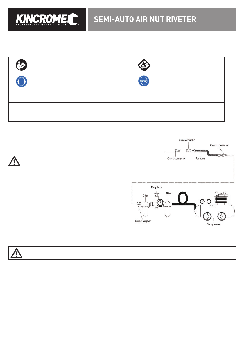
6) Additional Safety Instructions for Air Nut Riveters
a) Stay within air pressure capacity. Do notoperate the Air Nut Riveter above 90 psi.
b) Do not use the tool outside of the designed intent.
c) Fire the Riv-Nuts into an appropriate work surface only. This Air Nut Riveter is designed for use on metal objects only, and is
not suitable for soft surfaces.
d) Do not fire the Riv-Nuts too close to the edge of a workpiece. They may split the workpiece and cause it to fly free, causing
personalinjury.
e) Transport the Riveter safely. Disconnect the air supply when moving the tool in the workplace. Carry the tool by the handle
andavoid contact with the Trigger.

4
7) Description of Symbols
The followingsymbols could be shown on the tool:
Read the instruction manual before use.
Risk of Explosion
Wear Ear Protection
WearEye Protection
CFMCubic Feet per Minute flow SCFMCubic Feet per Minute flow at
standard conditions
PSIPounds per square inchof pressure NPT National pipe thread, tapered
Nm Newton meters of force BSPBritish standard pipe
Air Nut Riveter User Instructions
8) Before Starting
TO PREVENT SERIOUS INJURY FROM EXPLOSION:
Verify compressor is off before setup.Use only clean, dry,
regulated, compressed air to power this tool. Do not use
oxygen, carbon dioxide, combustible gases, or any other
bottled gas as a power source for this tool.
1. It is recommended afilter, regulator with pressure gauge, oiler,
in-line shut-off valve, and quick coupler be fitted for optimal
operation, as shown on Figure A.
2. An in-line shut-off ball valve is animportant safety device,
it will shut-off the air supply even if the air hoseis ruptured.
The shut-off valve should be a ball valve becauseit can be
closedquickly.
Note: If an automatic oiler system is not used, add a 4 to 5 drops of
Kincrome Air Tool Oil to the air inlet before operation.
Add a 1-2 more drops every hour of continual use.
3. Attach an air hose to the compressor’s air outlet. Connect the air hose to the Nitto Style Fitting (10) of the tool.Other
components, such as a quick connect fittingand quick connect coupler, will make operation more efficient, but are not required.
WARNING! Do not installa quick coupler directly on the tool. Couplers contains anair valve that will allow the air tool
to retain pressure and inadvertently operate after theair supply is disconnected.
4. The air hose must be long enough to reachthe work area and allow free movementwhile working. Do not exceed 10 metres.
5. Turn on the air compressor according to the manufacturer’s directions and allow the tank to build up pressure until it cuts-off.
6. Adjust the air compressor’s regulator so that the air output is at the tools recommended working pressure, the output must not
exceed the tool’s maximum air pressure at any time. Adjust the pressure gradually, while checking the air outputgauge to set
the optimal pressure range. Do not exceed 90 PSI.
7. Inspect all air connections for leaks. Repair any leaks.
8. If the tool is not being used, turn off and detach the air supply, safely discharge any residual air pressure, and releasethe
Trigger (2) and/or turnthe tools switch to its off position to prevent inadvertent operation.
Figure A

5
9) Assembly
Connectingthe Air Supply to the Air Nut Riveter
1. Wrap teflon tape (not supplied) around the Nitto Style Fitting (10) approximately 4 to 5 times to ensure a leak free seal.
2. Screw in Nitto Style Fitting (10) to the Air Inlet (1) of the Air Nut Riveter.
3. Using one of the supplied Multi Jaw Spanner (11e) or a 14mm Spanner (not supplied) fasten the Nitto Style Fitting (10).
4. Pullbackthe female coupler on your air hose, and feed over the Nitto Style Fitting (10).
5. Release the female coupler on your air hose. You should now have a leak free, air supply to your tool.
Changing Air Nut Riveter Mandrels (3) : (M4, M5, M6, M8, M10)
WARNING! Make sure the Air Nut Riveter is disconnected from its air supply hose prior to performing any maintenance,
service, or changing accessories.
1. Unscrew the Nose Piece (4) and Nose Piece Locking Nut (5) anti-clockwise and remove from the Air Nut Riveter.
2. Using one of the supplied Multi Jaw Spanner (11d) or a 28mm spanner (not supplied), remove the frame head, by turning
anti-clockwise and remove from the Air Nut Riveter. The Mandrel (3) and Rear Mandrel Housing (12) should
now be exposed (Fig 1).
3. Holdthe Rear Mandrel Housing (12) firmly with one of the Multi Jaw Spanner (11a) while using the otherMulti Jaw Spanner
(11b) to remove the currently installed Mandrel (3) by rotating clockwise.
4. Select your desired Mandrel (3) for the task at hand, and finger tighten it onto the Rear Mandrel Housing (12) anti-clockwiseas
the mandrel threads are reversed.
5. Holdthe Rear Mandrel Housing (12) firmly with one of the supplied Multi Jaw Spanner (11a) while using the otherMulti Jaw
Spanner (11b) to tighten the NEWLY installed Mandrel (3) by rotating anti-clockwise.
6. Reinstallthe frame head with your hands, then use the supplied Multi Jaw Spanner (11d) oruse a 28mm spanner (not supplied)
to tighten by rotating clockwise.
7. Reinstallthe Nose Piece Locking Nut (5) to the appropriate NosePiece (4), then thread the Nose Piece (4) to the Air Nut Riveter.
8. Air Nut Riveter is now ready for use.
10)Operation
AluminiumRivets Capacity Steel Rivets Capacity Stainless RivetsCapacity
M4 M4 M4
M5 M5 M5
M6 M6 M6
M8 M8 -
M10 M10 -
1. Ensure the desired Mandrel (3) has been installed (refer to ‘changingthe Air Nut Riveter Mandrels" shown above).
2. Using a drill (not supplied), drill into the material you wish to Riv-Nut.
3. Attach an air hose to the Nitto Style Fitting(10) covered in the assembly “Before Starting” section of this manual.
12
Fig 1
3

6
4. Turn on your compressor, andset the regulator between 70-90psi.
Caution: The Air Nut Riveter should never exceed 90 PSI. Doing somay cause injury to person or damage to the tool.
5. Threadthe Riv-Nut onto theMandrel (3) & set the depth via the Nose Piece Locking Nut (5).
Caution: Be careful when assemblingRiv-Nut’s, DO NOT press Trigger (2),Injury may occur!
6. Insert the Riv-Nut through the pre drilled hole in the work piece/material from step 3, and hold steady with your hand.
7. Hold the Air Nut Riveter firmly against workpiece with both hands, and squeeze the Trigger (2) to activate the Air Nut Riveter.
8. Release the Trigger (2) and remove the Air Nut Riveter from the workpiece, by rotating the Manual Mandrel Remover (7)
anti-clockwise untilit’s free from the Riv-Nut.
9. When you are finished using the Air Nut Riveter, disconnect the tool from your air hose and purge any remaining air, by
depressing the Trigger (2).
11)Cleaning, Maintenance, and Lubrication
Note: These procedures are in addition to the regular checks and maintenance explained as part of the regular operation of the
air-operated tool.
Lubrication (Air Tool Oil)
1. Disconnect the tool from the air supply holdingit sothe Air Inlet (1) faces up.
2. Depress the Trigger (2) and put 4 to 5 drops ofKincrome air tool oilin the Air Inlet (1). Holding the Trigger (2) down helps
circulate oil through the Air Nut Riveter.
3. Reconnect the Air Nut Riveter to the air supply.
To Prime The Air Nut Riveter (Hydraulic Oil)
WARNING! Make sure the Air Nut Riveter is disconnected from its air supply hose prior to performing any maintenance,
service, or changing accessories.
1. Disconnect the tool from the air supply holdingit sothe Air Inlet (1) faces up.
2. Usea 24mm Riveter Ring Spanner or socket (not supplied) to unscrew and remove
the Lock Nut (9) located at thebottom of the Air Nut Riveter.
3. Usea pair of pliers (not included) to remove the Piston Assembly from theCylinder (8).
4. Clean inside of the Cylinder (8) and lubricate cover seal.
5. Hold the Cylinder (8) upside down, and pour in hydraulic oil such as K12400 Kincrome
Hydraulic Jack Oil (not included).
Note: The fill level should only reach the top of the Frame.
6. Insert the Piston Assembly back into the Cylinder (8).
7. Usea 24mm Ring Spanner or socket (not supplied) to firmly screw the Lock Nut (9) back
onto the Cylinder (8).
Storage
1. Avoid storing the Air Nut Riveter ina locationsubject to high humidity. If the tool is left as it
is used, the residual moisture inside the tool can cause rust. Before storing and after
operation, oil the tool and run it for a short time.
2. Regular inspectionshould be carried out of the Air Nut Riveter.
Pleasescan QR Code for
'How to Prime your Riveter'
instruction video.
Please Note: The K13272 does
NOT come withthe tool inthe
video. A 24mm Ring Spanner
or socket must be supplied by
the end user.

7
12) Warranty
Warranty given by Kincrome Australia Pty Ltd of 3 Lakeview Drive, Caribbean Park, Scoresby, Victoria (Tel 1300 657 528).
The applicable warranty period (24 months) commences on the date that the product is purchased. If this product has
materials or workmanship defects (other than defects caused by abnormal or non warranted use) you can, at your cost,
send the product to place of purchase, an authorised Kincrome service agent or one of Kincromes addresses for repair or
replacement. Your rights under this warranty are in addition to any other rights you have under the Australian Consumer
Law or other applicable laws. Our goods come with guarantees that cannot be excluded under the Australian Consumer
Law. You are entitled to a replacement or refund for a major failure and compensation for any other reasonably fore-
seeable loss or damage. You are also entitled to have the goods repaired or replaced if the goods fail to be of acceptable
quality and the failure does not amount to a major failure. For further details please visit www.kincrome.com.au or call us.
Due to minor changes in design or manufacture, the product you purchase may sometimes differ from the one shown on
the packaging.
IMPORTANT! If the tool fails to operate correctly, call customer service on 1800 657 528 for advice on the best resolution
for your situation. If a resolution cannot be achieved over the phone please take the tool and all related accessories to an
authorised service centre or place of purchase showing proof of purchase for assistance.
13) Parts Breakdown

8
PartNoDescriptionQty
K13272-1 Nosepieces 1
•K13272-1A Nosepieces, M4 1
•K13272-1B Nosepieces, M5 1
•K13272-1C Nosepieces, M6 1
•K13272-1D Nosepieces, M8 1
•K13272-1E Nosepieces, M10 1
•K13272-02 Nose Nut 1
K13272-03 Stroke Adaptor Cover 1
K13272-04 Connector Housing 1
•K13272-05 Jaw Case, Rear 1
•K13272-06A Screw Mandrel (M4) 1
•K13272-06B Screw Mandrel (M5) 1
•K13272-06C Screw Mandrel (M6) 1
•K13272-06D Screw Mandrel (M8) 1
•K13272-06E Screw Mandrel (M10) 1
•K13272-07 Rear Mandrel Housing 1
#K13272-08 E Ring 1
K13272-09 Return Tube 1
K13272-10 Lock Nut 1
#K13272-11 O Ring 2
K13272-12 Backup Ring 1
K13272-13 Frame 1
K13272-14 Piston 1
#K13272-15 O Ring 1
K13272-16 Backup Ring 1
K13272-17 Piston Ring 1
K13272-18 Hanging Clip 1
#K13272-19 O Ring 1
K13272-20 Frame Cap 1
K13272-21 Safety Cap Nut 1
#K13272-22 O Ring 2
K13272-23 Backup Ring 1
Part NoDescription Qty
K13272-24 Cylinder 1
K13272-25 Rubber Cushion 1
K13272-26 Lock Nut, Frame 1
K13272-27 Stem, Air Piston 1
K13272-28 Plate, Large 1
K13272-29 Piston Ring 1
K13272-30 Washer 1
K13272-31 Plate, Large 1
K13272-32 Lock Nut, Piston 1
# K13272-33 O-Ring 1
K13272-34 Cap, Cylinder 1
K13272-35 SpringPin 1
K13272-36 SpringPin 1
K13272-37 Pusher, Valve 1
K13272-38 Spring, Valve 1
K13272-39 Collar, Valve 1
# K13272-40 O-Ring 1
K13272-41 SpringPin 1
K13272-42 SpringPin 1
K13272-43 Valve 1
K13272-44 Spring, Valve 1
# K13272-45 O-Ring 1
K13272-46 Cap, Valve 1
K13272-47 SpringPin 2
K13272-48 Trigger 1
K13272-49 Trigger Rod 1
K13272-50 Trigger Lever 1
• K13272-52 Multi Jaw Spanner 2
#K13272-53 O Ring 1
• K13272-54 O Ring Kit 1
• Indicated stocked spare parts. We reserve the right to change spare parts at any time withoutnotice.
# Indicates contents included in K13272-54 O Ring Kit

www.kincrome.com.au
Table of contents
Other kincrome Rivet Tools manuals