manuals.online logo
Brands
  1. Home
  2. •
  3. Brands
  4. •
  5. Vestamatic
  6. •
  7. Controllers
  8. •
  9. Vestamatic IF SMI KNX 230VAC 16 User manual

Vestamatic IF SMI KNX 230VAC 16 User manual

Subject to modifications.© Vestamatic GmbH
Art.-Nr.: 3060 002 DE 0319 A03 • Vestamatic GmbH • Dohrweg 27 • D-41066 Mönchengladbach • www.vestamatic.de
1/4
G
IF SMI KNX 16
IF SMI KNX
230 VAC / 24VDC 16
Installation and Operating Instructions
IF SMI KNX 230VAC 16 Art.-no.: 01092517
IF SMI KNX 24VDC 16 Art.-no.: 01092516
Motor control for operating of
230VAC or 24VDC LoVo SMI drives
G
3060 002 GB 0319 A03
1. Basic safety instructions
1.1 Intended use
1.2 Foreseeable misuse
1.3 Personnel’s qualification
1.4 Signage
2. Product description
3. Declaration of conformity
4. Technical data
5. Installation / Mounting
5.1 Electrical connection – Overview
5.2 Configuration
5.3 Commissioning / Test run
6. Design and Function
6.1 Complete overview
6.2 Control and display elements
6.3 Local operation
7. Operation
7.1 Manual operation
7.2 Automatic operation
8. Troubleshooting
9. Re-learn motor addresses
10. Maintenance
11. Warranty
12. Disposal of waste
13. Service / Contact
CONTENTS
CAUTION!
Material damage!
Incorrect wiring and configuration of the device can lead to dam-
age up to total failure.
– Ensure that the supply voltage corresponds to the specifica-
tions from the technical data for the device.
– Ensure that all external devices like push buttons and motors
are connected correctly according to the wiring diagrams.
– Refer to technical documentation of the motor manufacturer
for notes on required settings such as relais switching times.
– Refer to the software-helpfile for details on the configuration.
Ä
1. Basic safety instructions
DANGER!
Danger of life!
There is a risk of life when touching live parts.
– All tasks must be carried out exclusively by qualified personnel.
– Disconnect all power supplies before starting work.
1.1 Intended use
The motor control units are intended to control drives for blinds, awnings,
large louvre blades, roller shutters, windows, light domes, etc. within the
specified limits.
Any other use or extended use is considered to be improper.
1.2 Foreseeable misuse
Any use for a purpose other than the above mentioned purpose is improper.
The risk of improper use or misuse is borne solely by the operator.
All types of claims due to damage arising from improper use are excluded.
1.3 Personnel’s qualification
Improper use can cause considerable personal injury and material dam-
age!
All tasks for installation, connection and commissioning must be carried
out exclusively by a qualified electrician.
A qualified electrician is able to carry out work on electrical installations
due to her/his professional training, knowledge, and experience as well as
knowledge of the relevant standards and regulations. She/he can identify
and avoid possible dangers.
The qualified electrician is trained for the specific place of employment
in which she/he is working and is aware of the relevant standards and
regulations.
1.4 Signage
Symbol
Meaning
Ä
General warning
Electrostatic discharge
p
CE label
This product complies with the essential requirements. The
Declaration of Conformity concerning this product is available on
our website: www.vestamatic.com
3. Declaration of conformity
p
2. Product description
The motor control units are designed for the control of max. 16 LoVo drives
230VAC or 24VDC with SMI interface for blinds, awnings, large louvre
blades, roller shutters, windows, light domes, etc. in a KNX bus system.
Each device has 4 lines and inputs for the connection of 4 conventional
blind switches or 8 potential-free contacts.
Each channel or motor can be controlled individually via the KNX bus
and operating states, position and fault messages for the connected
drives/blinds can be transmitted.
Art.-no. Article description
01092517 IF SMI KNX 230VAC 16
01092516 IF SMI KNX 24VDC 16
Subject to modifications.© Vestamatic GmbH
Art.-Nr.: 3060 002 DE 0319 A03 • Vestamatic GmbH • Dohrweg 27 • D-41066 Mönchengladbach • www.vestamatic.de
2/4
G
IF SMI KNX 16
4. Technical data
General
Operating temperature:
°C
dry rooms
(free of condensation)
+5 °C (41 °F) to +45 °C (106 °F)
pollution index 2
Mounting: DIN rail 35 mm
or equivalent
Dimensions (W × H × D): mm 72 × 90.5 × 62 (4 SU)
Weight: g 200
Binary inputs: 8
Motor outputs: 4
Connection data
Supply voltage: VAC 230 ± 10 %
Hz 50
Cable: 2 wires (single or fine wire)
Wire cross-section: mm2) 2.5
Terminal tightening torque: Nm 0.4
Fuse protection: A 10
IP class: IP 20
Electrical protection class: III
NOTE!
The connection and the wiring of the local operation units and
the KNX bus must be carried out according to the current SELV
requirements.
I
Motor connection (outputs)
Motor type: VAC SMI 230
VDC SMI LoVo 24
Leitung: 2 wires (single or fine wire)
Wire cross-section: mm2) 2.5
Terminal tightening torque: Nm 0.4
5. Installation / Mounting
To mount the actuator proceed as follows:
– Place the module on the DIN rail in the desired position and lock in.
Local operation (inputs)
Voltage: VDC 8
Current: mA 2
Cable: 3 wires (single or fine wire)
Wire cross-section: mm2) 1.5
Terminal tightening torque: Nm 0.25
Cable length: mmax. 100
Operation via: push button or
switch potential-free contact
KNX
Bus connector: mm Ø 0.5 ... 0.8 (single wire)
Bus cable: according to KNX standard
5.1 Electrical connection – Overview
Wiring diagram
X Power
NOTE!
The drives are not supplied via the actuator. The data sheets and
information of the drives are to be considered. Mixed operation
between AC and LoVo drives is not permitted.
I
Motor
Connect motors as follows:
Motor connection terminals Destination
I+ / I- I+ and I- of SMI line
NOTE!
Communication to the SMI drives only works properly when
I+ and I- are connected correct.
I
KNX-Bus
Connect the KNX bus connector to the KNX bus.
Supply voltage
Connect supply voltage to the motor control unit as follows:
Power
L
Phase 230VAC
N
Neutral conductor
Local operation
Several push buttons can be connected to one local operation input.
NOTE!
It is possible to connect one push button to several local oper-
ation inputs.
This push button may only be connected to one SMI actuator.
I
Local operation inputs Destination
Push button “UP”
Push button “DOWN”
+Push button
Subject to modifications.© Vestamatic GmbH
Art.-Nr.: 3060 002 DE 0319 A03 • Vestamatic GmbH • Dohrweg 27 • D-41066 Mönchengladbach • www.vestamatic.de
3/4
G
IF SMI KNX 16
6.2. Control and display elements
Test buttons UP / DOWN
– To control the motor outputs in test mode.
– Short key press (< 0.4 s) > step / stop.
– Long key press (> 0.4 s) > movement command end position.
– Additionally the test buttons UP/DOWN can be used to re-learn the motor
addressing (for further information see chapter 8., “Troubleshooting”.
Status display motor output
– LED is off = channel is in normal-/automatic mode.
– LED flashes “GREEN” = automatic lock is active
(for further information see software-helpfile).
– LED lights continuously “GREEN” = channel is in test mode, control
via test buttons is activated.
– LED flashes “RED” = security lock is active
(for further information see software-helpfile).
– LED lights continuously “RED” > SMI motor output error
(for ruther information see chapter 8., “Troubleshooting”).
Status display local operation
– The corresponding LED (UP / DOWN) lights “GREEN” as long as the
button of the local operation is pressed.
Status display ready for operation
– Lights continuously “GREEN” when the device is ready for operation.
Programming button
– Activates/deactivates the programming mode
(supply voltage and KNX bus voltage must be available).
Programming LED
– Lights continuously “RED” when the programming mode is activated.
Test button “M”
– Used to select a motor output for direct operation via the test buttons
UP/DOWN (test mode).
If a motor output is in test mode, the corresponding status LED lights
continuously “GREEN”.
– By briefly pressing the “M” button all 4 channels are switched to the
test mode.
– Each additional operation switches through the individual channels
1, 2, 3 and 4.
– After 6 operations all channels are in normal mode again.
– Additionally the “M” button can be used to reset the device (for further
information see chapter 8., “Troubleshooting”).
5.2 Configuration
– The configuration of the motor control unit is done via ETS from version
4.0 of KNX-Association.
5.3 Commissioning / Test run
For commissioning of the motor control unit proceed as follows:
– Check the condition of the device and the tight attachment of the terminals
and connections.
– Switch on the supply voltage.
– Check supply voltage and status display on the device.
– Check function of the SMI drives by means of test buttons – if communi-
cation to the SMI drives is not possible, check SMI wiring.
– Check the local operation –
if the function is reversed, correct the local operation connection.
– Move blinds, awnings, large louvre blades, roller shutters, windows, light
domes, etc. into a safe end position.
– Mount all protective covers.
– Maintain system documentation and, if necessary, affix labels and/or
signs.
7. Operation
Automatic operation is performed according to the parameters specified
in the ETS configuration. The control command received via the KNX bus
are considered.
The manual operation is done via the local operation inputs of the motor
control unit by means of push buttons or switches (see chapter 6.3, „Local
operation“) and/or via the KNX system (see software-helpfile).
7.1 Manual operation 7.2 Automatic operation
Requirements
– Supply voltage and KNX bus voltage must be present.
Approach
– Connect PC / Laptop to the KNX bus via programming interface.
– Set the motor control unit to programming mode by pushing the pro-
gramming button, the programming LED lights continuously “RED”.
– Download the physical address and the application program.
NOTE!
For details about the configuration software see documentation
of KNX-Association.
I
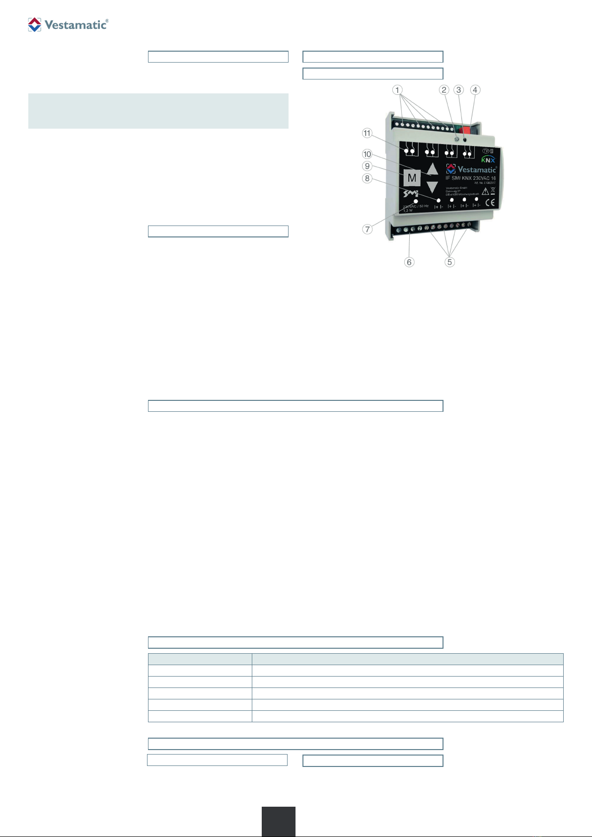
6. Design and function
1. Push button local operation-
(UP/DOWN/+)
2. Programming LED
3. Programming button
4. KNX bus connector
5. Motor connection terminals
6. Connection terminal supply
voltage
7. Status display ready for
operation
8. Status display motor output
9. Test button “M”
10. Test buttons (UP/DOWN)
11. Status display local operation
6.1 Complete overview
Location of control and display elements
6.3. Local operation
The local operation can be in-
stalled as push button or switch.
If no adjustments have been
made in the ETS configuration,
the functionality is according to
the table beside:
Function Control
“Upper end positon”
long key press “UP” (> 0.4s)
“Lower end position”
long key press “DOWN” (> 0.4s)
“Shading position”
long key press “DOWN” (> 0.4s), immediately followed by short key press “DOWN” (<0.4s)
“STOP”
short key press in opposite direction of current movement (<0.4s)
“Move slats”
short key press when stationary (<0.4s)
Subject to modifications.© Vestamatic GmbH
Art.-Nr.: 3060 002 GB 0319 A03 • Vestamatic GmbH • Dohrweg 27 • D-41066 Mönchengladbach • www.vestamatic.com
4/4
G
IF SMI KNX 16
The disposal of electrical equipment and batteries in household
waste is strictly forbidden.
The symbol (dustbin crossed out, in line with WEEE Appendix IX)
indicates separate collection of electrical and electronic products in
EU countries. Do not dispose of the device or battery in your house-
hold waste. Ask your town or local council about the return and
collection systems available in your area to dispose of this product.
É
12. Disposal of waste
11. Warranty
Principally, the General Terms and Conditions of the manufacturer, Vestamatic
GmbH apply. The terms and conditions are part of the sales documents
and handed over to the operator upon delivery. Liability claims for personal
or material damages are excluded when they can be attributed to one or
more of the following causes:
– Unintended use of the product.
– Opening of the product by the customer.
– Improper installation, commissioning, or operation of the product.
– Non-compliance with the technical specifications.
– Non-observance of the safety provisions and instructions of the Oper-
ating Instructions.
– Operation of the product with improperly installed connections, defective
safety devices or improperly installed safeguards.
– Modifications to the product.
13. Service/Contact
Vestamatic GmbH
Dohrweg 27
D-41066 Mönchengladbach / Germany
[email protected]
Tel.: +49 2161/29 408-0
8. Troubleshooting
Fault
Rectification
Motor error –
Status LED for the corresponding
motor lights continuously “RED”.
– Check motor connection, motor cable, and motor.
Device does not communicate via
KNX.
– Check supply voltage
(LED ready for operation must light continuously „GREEN“).
– Check KNX bus voltage
(programming LED can be switched on and off via the programming button).
No local/manual commands are
executed.
– Check whether the corresponding output is in test mode (status LED for the output lights continuously
“GREEN”) – press the “M” button several times to exit the test mode (all status LEDs of the outputs do
not light continuously “GREEN”).
– Check whether a security lock is active (status LED for the output flashes “RED”); the triggering and
reset conditions for a security lock are defined in the ETS configuration by the system integrator.
– Check local operation inputs and / or KNX communication.
No central/automatic commands are
executed.
– Check whether the corresponding output is in test mode (status LED for the output lights continuously
“GREEN”) – press the “M” button several times to exit the test mode (all status LEDs of the outputs do
not light continuously “GREEN”).
– Check whether a security lock is active (status LED for the output flashes “RED”); the triggering and
reset conditions for a security lock are defined in the ETS configuration by the system integrator.
– Check whether an automatic lock is active (status LED for the output flashes “GREEN”) –; the triggering
and reset conditions for an automatic lock are defined in the ETS configuration by the system integrator.
– Check the KNX communication.
NOTE!
If the listed troubleshooting procedures do not lead to the desired result,
please contact the customer service.
I
9. Re-learn motor addresses
If the motor addresses shall be re-learned (e.g. by a motor change), the
stored addresses can be deleted and re-learned.
– Switch motor output to test mode by pressing test button “M” (status
LED of the output is permanently “GREEN”).
– Press test buttons “UP” and “DOWN” simultaneously for at least 5s.
– New motors get a new address this way.
Reset the device to the factory setting
A reset must be carried out for resetting the device to the factory setting.
NOTE!
The reset will clear the entire configuration.
I
– Press test button “M” for at least 10s (all status displays of the motor
outputs flash alternately “RED” and “GREEN”.
– Press test button “M” again within 10s and keep it pressed for at least
10 more seconds (all status LEDs of the motor outputs light continously
“RED”).
– Press test button “M” again within 10s and keep it pressed for at least
10 more seconds (the device is reset to factory settings).
– The restart of the device is shown by flashing the status LEDs of inputs
and motor outputs.
10. Maintenance
The device is maintenance free.

This manual suits for next models

1

Other Vestamatic Controllers manuals

Vestamatic Rolltec Pico User manual

Vestamatic

Vestamatic Rolltec Pico User manual

Vestamatic MC P4 LoVo User manual

Vestamatic

Vestamatic MC P4 LoVo User manual

Vestamatic Quattro Lite User manual

Vestamatic

Vestamatic Quattro Lite User manual

Vestamatic DZ-Plus R User manual

Vestamatic

Vestamatic DZ-Plus R User manual

Vestamatic Touch Centre XL 4C Wired User manual

Vestamatic

Vestamatic Touch Centre XL 4C Wired User manual

Vestamatic MC P4 LoVo User manual

Vestamatic

Vestamatic MC P4 LoVo User manual

Popular Controllers manuals by other brands

Danfoss ISD Encoder Box operating instructions

Danfoss

Danfoss ISD Encoder Box operating instructions

Barber-Colman MACO Series installation manual

Barber-Colman

Barber-Colman MACO Series installation manual

STERIFLOW Mark 96A Series Installation & maintenance instructions

STERIFLOW

STERIFLOW Mark 96A Series Installation & maintenance instructions

Full Gauge Controls EVOLUTION TC-970E Log+ECO manual

Full Gauge Controls

Full Gauge Controls EVOLUTION TC-970E Log+ECO manual

IPS Controllers M790 owner's manual

IPS Controllers

IPS Controllers M790 owner's manual

Fishman TriplePlay installation guide

Fishman

Fishman TriplePlay installation guide

SMC Networks ITV2050-IL20-X399 Series Operation manual

SMC Networks

SMC Networks ITV2050-IL20-X399 Series Operation manual

GLIDEAWAY SOMERSTON quick start guide

GLIDEAWAY

GLIDEAWAY SOMERSTON quick start guide

Nexmosphere XC-760 quick start guide

Nexmosphere

Nexmosphere XC-760 quick start guide

THORLABS BBD202 user guide

THORLABS

THORLABS BBD202 user guide

Regin RVAN25-24A Instruction

Regin

Regin RVAN25-24A Instruction

Lantronix SLB quick start guide

Lantronix

Lantronix SLB quick start guide

Azbil C7G Installation and configuration manual

Azbil

Azbil C7G Installation and configuration manual

Vacon 100 INDUSTRIAL installation manual

Vacon

Vacon 100 INDUSTRIAL installation manual

VKB-Sim Mamba w/ MCG Pro quick guide

VKB-Sim

VKB-Sim Mamba w/ MCG Pro quick guide

Siemens SIMATIC EMS400S PSB-S operating instructions

Siemens

Siemens SIMATIC EMS400S PSB-S operating instructions

Hyco O188 user manual

Hyco

Hyco O188 user manual

Sevcon MillipaK 4QPM manual

Sevcon

Sevcon MillipaK 4QPM manual

manuals.online logo
manuals.online logoBrands
  • About & Mission
  • Contact us
  • Privacy Policy
  • Terms and Conditions

Copyright 2025 Manuals.Online. All Rights Reserved.