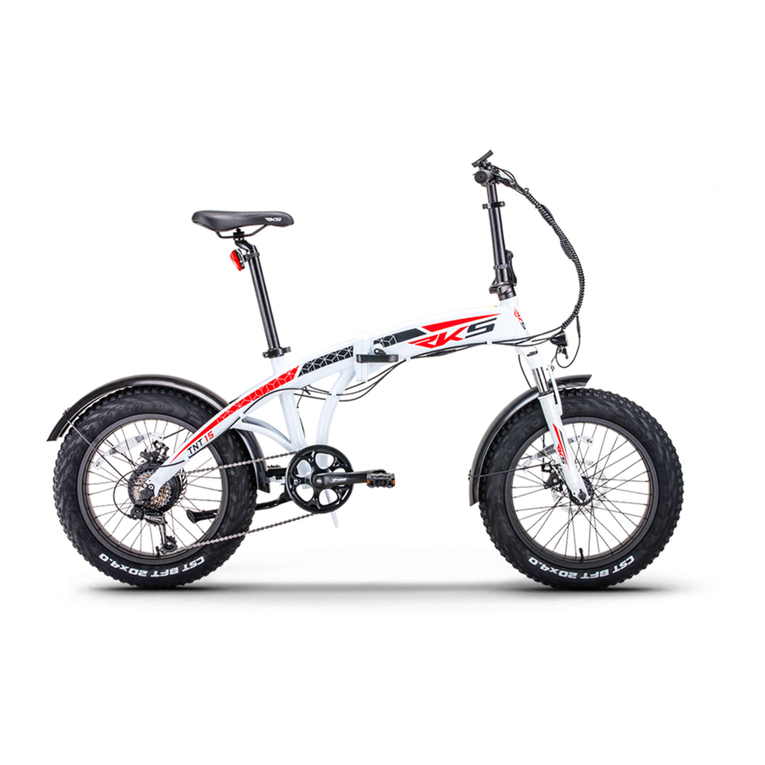
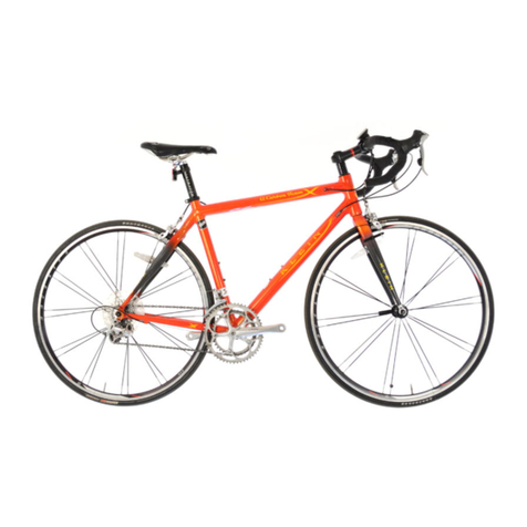
RKS TNT-5 User manual

TNT-5
USER MANUAL
www.rksmotor.eu

01
PREFACE
Our company makes RKS brand electric scooter become a kind of environmental protection type leisure traffic tool
instead of walk with elegant, beautiful shape and modern luxurious feeling by virtue of novel management model,
abundant technical force, perfect quality system, first-class workmanship equipments and an excellent professional
team of technology.
This scooter has safe and reasonable structure and design, adopts high-efficient and superior-performance electric
hub, high-energy seal type free of maintenance jelly battery and front fork shock-preventing device to improve the
comfort of riding. It has a kind of function for riding pedal driving. It is a kind of ideal traffic tool instead of walk.
ŸFront and rear suspension system providing a smooth and comfortable riding.
ŸDigital controller with indicator and protection from over voltage and under voltage.
ŸHigh-efficient brushless DC motor.
Dear Users;
ŸBrake system with power cut-off ability to ensure safe riding.
In order that this scooter can offer better services for you, please read carefully this user's manual before use, please
make sure to follow the requirements of this user's manual in order to make your electric scooter in the best status
and make you to travel more safely, comfortably and successfully.
ŸBattery with high performance offering stronger current and longer distance for drive
This product is designed for transportation and is environmental friendly. Below are the characteristics and
advantages of this electric scooter.
TNT-5

02
WARNING
TNT-5
Persons less than 16 years old (include 16 years old) are not allowed ride e-bikes
This is normal Folding electric bicycle,this one is with LCD display,

03
CONGRATULATIONS
ŸDerailleur/ Roller brake Derailleur/
For mechanical equipment:
Please read this instruction manual carefully and thoroughly before riding, as it contains sufficient information,
which is very important in safety, maintenance and simple assembly. It is the owner's responsibility for reading this
manual before riding this bike.
ŸInternal gear hub / Roller brake or coaster brake
ŸInternal gear hub / V-brake or disc brake
For mechanical equipment, an electric bicycle differs only slightly from a non-electric bike.
ŸV-brake or disc brake
For electric equipment:
ŸThe battery-pack with rear carrier or on the down tube
ŸThe motor in the rear or front wheel hub
The user's instruction manual includes two sections, one is mechanical section, and another is electric section. This
instruction is applied to the electric bikes with following equipment:
ŸThe controller on a box next to battery or integrated to the battery-pack
ŸOperation panel is installed to handle bar
First of all, congratulation on your purchasing of our electric bicycle(or pedelec), which is carefully designed and
manufactured under strict quality control according to the current European standard EN 15194:2017
TNT-5

04
MANUAL FOR MECHANICAL PARTS
1. Conditions for Riding This Electric Bicycles
2. Selection and Set-up
4. Routine Maintenance Check and Lubrication
5. Assembly Instructions
Contents
1.Conditions for Riding this Electric Bicycles
3. Safe Cycling and Safety Tips
WARNING
This electric bicycle is designed for riding on a road or a paved surface where the tires do not lose ground contact, and
this electric bicycle must be under proper maintained according to the instruction of this manual. The maximum
weight of the rider and load is required to be less than 200lb (or 90kg).
You are warned that you take the consequences such as personal injury, damage, or losses if you breach the
above conditions and in the meanwhile, the warranty will be void automatically.
TNT-5

05
MANUAL FOR MECHANICAL PARTS
The seat can be easily moved either up or down. Adjust the seat to keep the rider's knee maintaining a slight bend
when his foot is in the lowest pedaling position(refer to fig. 3). Handlebar stem is approximately on the same level as
saddle or slightly lower. For some more adjustment tips, please refer to fig. 4 as below:
2.Selection and Set-up
2.1 Saddle and Handlebar Stem Adjustment
TNT-5

06
If your seat post is not inserted up to the minimum insertion mark, the seat post may break
(refer to fig. 5)
WARNING
WARNING
handle stem minimum insertion mark on traditional quill stems must not be visible above the top
of headset. If the stem is extended beyond the minimum insertion mark the stem may break or
weaken the fork steering tube.
Once the saddle is at the correct height, make sure the seat post should be up to its minimum
insertion mark.
3. Safe Cycling and Safety Tip
3.1. Checking Points Before Riding
Before you ride your electric bicycle at any time, make sure it is in a safe operating condition. Particular check the
following items:/brake line /rope fastening screw/fixed screw/rear side wire.
ŸElectric bicycles nuts, bolts, quick-release and parts are fastened tight and no worn or damage;
ŸRiding position is comfortable;
ŸSteering is free with no excessive play;
MANUAL FOR MECHANICAL PARTS
TNT-5

07
ŸDo not hold on to another vehicle with another hand;
ŸDo not hang items over the handlebars to impede steering or catch in the front wheel;
ŸTires are in good condition and inflated to correct pressure
ŸAll reflectors are in position
3.2. Do Not When Riding
After you have made any adjustment to your electric bicycle, check that all nuts and bolts are securely tightened and
cables are free from kinks and fixed securely to the electric bicycles frame. Every six months, your electric bicycle
should be professionally checked to ensure that it is in correct and safe working order. It is the responsibility of the
rider to ensure all parts are in working order prior to riding this electric bicycle.
ŸWheels run true and hub bearings are correctly adjusted;
ŸGears are correctly adjusted
ŸPedals are securely tightened to pedal cranks
ŸDo not carry a passenger unless the cycle is equipped to do so;
ŸWheels are properly secured and locked to frame/fork;
Do not ride without wearing an approved helmet, which must meet European/USA standard or the same effect
(comply with the law, rule or regulations in your local area);
ŸDo not ride on the same side of road as oncoming traffic;
ŸDo not ride too close to another vehicle.
MANUAL FOR MECHANICAL PARTS TNT-5

08
Warning: As with all mechanical components, the bicycle is subjected to wear and high stresses. Different materials
and components may react to wear or fatigue in different ways. If the design life of a component has been exceeded, it
may suddenly fail possibly causing injuries to the rider. Any form of crack, scratches or change of coloring in highly
stressed areas indicate that the life of the component has been reached and it should be replaced.
Warning of Night Riding: we recommend you minimize the times you ride after dark. If you have to be out on your
electric bicycle at night, you must comply with the relative law, rule or regulations in your local area, using a
headlight(white) and taillight(red) on your electric bicycle in addition to the all-around reflectors fitted. For more
safety, wear light colored clothing with
4. Routine Maintenance Check and Lubrication
Warning: It is important to use only genuine replacement parts for several safety-critical components.
Warning of Wet Weather Riding: No brakes work as well under wet or icy conditions as they do under dry conditions.
The braking distance in wet weather would be longer than those in dry, and you should take special precautions to
assure safe stopping. Ride slowlier than normal and apply your brakes well in advance of anticipated stops.
reflective stripes. Check that the reflectors are firmly secured in the correct position and clean and not obscured.
Damaged reflectors must be replaced immediately.
MANUAL FOR MECHANICAL PARTS
TNT-5

09
To keep the electric bicycle functioning well, the following routine maintenance and lubrication is necessary for you
Wash cycle weekly with warm soapy water
and dry it by rubbing with a soft cloth
Remove and clean, lubricate chain,
derailleur gears and all cables. Check and
replace as required.
NB
Warning: When the rim becomes part of
the brake system (such as the conditions
of V-brake and caliper brake), it is very
important to check the rim wear monthly
and adjust the brake shoes accordingly to
make the clearance at 1-1.5mm from the
track of rim. The wear of rim may destroy
the braking and result in personal injury to
the rider or others.
Half Yearly
MANUAL FOR MECHANICAL PARTS TNT-5

10
Remove, clean and regrease bearing
yearly, checking if replacements
required.
A - Headset B - Mudguards
Check the mudguards are clean and
tight. Ensure the mudguards are
secure and undamaged. Replace if
neccesary.
O - Bottom Bracket
Clean,regrease yearly checking for
wear.
Ensure stem nuts and bolts are tight
B - Stem Nuts
Check the quick release is tight,
ensure the mudguards
are secure and undamaged, replace
if necessary
I - Quick release P - Gears
Front and Rear Lightly oil moving
parts. Maintain adjustments of front
and rear derailleurs.
C - Handlebars
Check handlebar bolt is tight. Check
brake lever securely mounted to
bars and brakes stop smoothly and
efficiently.
Grease bearings monthly. Adjust
cones to avoid free play side to side.
J - Wheel Hubs Q - Chain cover
Check the chain cover is secure and
undamaged, replace it if necessary
D - Brakes
Lightly oil exposed cables monthly.
Maintain adjustment and replace
brake blocks when worn, brake
cables when frayed.
K - Reflector (Pedal)
Check all fitting are secure. Be sure seat and stem nuts are tight
R - Seat and Stem Nuts
MANUAL FOR MECHANICAL PARTS
TNT-5

11
E-Battery light (front and rear)
Ensure the front and rear battery
light are secure and undamaged.
Replace if neccesary.
L-Cranks
Grease bearing monthly, check
that axle bolts and cotterpin bolts
are tight, check for free play in
bottom bracket.
Lightly oil bearings monthly
S-Pedals
F-Front suspension unit
Dealer adjustment only
M-Chain
Keep light oiled weekly, clean and
lubricate half yealy.
G-Tyres
Check for cuts and wear, Maintain
pressure indicated on tires wall for
maximum Efficiency.
Check that axles are sealed and
secured properly. Rim should be
kept free from wax, oil, grease and
glue. Check for loose or missing
spokes. (see warning below)
N-Wheels
you can refer to the manual for the
electrical parts.
U-The electrical parts
MANUAL FOR MECHANICAL PARTS TNT-5

12
MANUAL FOR MECHANICAL PARTS
Step 1: Preparation:
Here is some important information for electric bicycles assembly, which is very useful for your maintaining your
electric bicycle, and especially helpful when you purchase our e-bikess which is partly assembled and packed in a
carton.
Take the electric bicycle and parts out of the carton and detach all parts that are tied to the frame. Be careful not to
scratch the frame or cut the tire removing the wrapping. Then carefully examine the carton for loose parts and make
certain that no parts are left.
5. Assembly Instruction
5. Open the seat post quick release lever(Fig. 8).
Insert the seat post into the seat tube to a
Step 2: Seat Assembly (refer to fig.7)
2. Insert the seat post into the seat clamp. The seat
post must extend at least 1/4 inch(6-7mm) above the
top edge of the seat clamp.
3. Re-tighten the seat clamp nuts on both sides(hand
tight).
1. Loosen the seat clamp nuts(both sides)
4. Push the seat post into the seat tube of the electric
bicycle frame and rotate the seat until the tip of the
seat is directly above the top tube of the frame.
THE SEAT POST
MUST BE INSERTED
INTO THE SEAT
TUBE AT A DEPTH
WHERE THE
MINIMUM
INSERTION LINE IS
NOT VISIBLE!!!
TNT-5

13
sufficient depth so that the minimum insertion line is no longer showing.
6. When you are satisfied with the height of the seat post, close the seat post
quick release lever. The tightness of the lever is adjusted by rotating the
adjustment nut opposite the quick release lever. Turn the nut by hand to adjust
the tension while holding the lever stable.
MANUAL FOR MECHANICAL PARTS
Step 3: Handlebar & Handlebar Stem Assembly (refer to fig. 9 and 10)
As an usual situation, in our factory, the handlebar
have been pre- assembled together with brake
levers, shifter levers. Be sure that the longer cable
is fixed to the right lever (rear brake) and shorter
cable to the left (front brake), or according to your
local rule and practice (Note: In some area, such as
UK, the cables are required to be arranged in the
opposite way). Since your cycle may be fitted with
an adjustable, a standard stem or an A-head
stem(refer to fig.9 ), you must always check that all
the bolts are tight before cycling.
TNT-5

14
MANUAL FOR MECHANICAL PARTS
1. Push the handlebar stem into the fork tube (head of the frame ) to the minimum height line that is marked on the
side of the handlebar stem. Itmight be necessary to loosen the expender bolt so that the stem can slide into the fork
tube, until you get your desired height of the handlebar stem
6. Be sure that your handlebar and stem assembles are properly tight before riding. The handlebar should not rotate
in the stem. When you straddle and grip the front wheel between your knees, the handlebar should not be able to turn
when you apply pressure horizontally. Refer to (fig. 10)
3. Loosen the handlebar clamp bolt and nut from the stem.
4. Position the handlebar at the desired angle. Make sure that the stem is in the center of the handlebar
Note: Some models require a 6mm allen key.(Tightening torque: 18N.m or 14 footlbs.torque)
Based on the situation of standard handlebar stem, please follow the instruction below:
2. Align the handlebar stem with the front wheel(see fig.10). Tighten securely the expender bolt with an adjustable
wrench.
5. Tighten securely the handlebar clamp bolt (Tightening torque: 18N.m or 14 foot. lbs)
Note: Under the situation of A-head stem, you make the similar operation as the above. Compression bolt tightening
torque: 23N.m or 17 foot lbs. torque; stem clamp bolt tightening torque: 12N.m or 9 foot. lbs
TNT-5

15
3. Screw the pedal marked “L” into the left side of the crank assemble. Turn the left pedal (by hand) in the
counterclockwise direction. Tighten securely with an adjustable wrench or the plate wrench special for
pedals(Tightening torque: 34N.m or 26foot.lbs).
Step 4 Attaching Pedals(refer to fig. 11) :
2. Screw the pedal marked ”R” into the right side of the crank assembly (chain side of electric bicycles). Turn the (by
hand) in the clockwise direction. Tighten securely with an adjustable wrench or the plate wrench special for
pedals(Tightening torque: 34N.m or 26foot.lbs).
1. The pedals are marked with either a “R” or “ L” on the threaded end of the pedal axle.
MANUAL FOR MECHANICAL PARTS TNT-5

16
Step 5 Brake Adjustments
c. Depress the brake lever about 10times as in normal brake operation and check that everything is operating
correctly and that the shoes clearance is correct before using the brakes.
b. Adjust the balance with the spring tension adjustment screws.
a. Press the inner cable through the inner cable lead, and after setting so that the total of the clearance between the
left and right shoes and the rims is 2mm, tighten the cable fixing bolt, tightening torque: 6-8N.m or 5- 6foot.lbs .
The brake on your electric bicycle should have been adjusted correctly in our factory, however, as cables do stretch, it
is important to check the adjustment of your brakes after your first riding. Most brakes will need some adjustment
after being used a few times.
V-brake Adjustment(refer to fig. 12) :
MANUAL FOR MECHANICAL PARTS
Note: If you are still failed to well adjust the V-brakes, we
strongly recommend it being done by professionals. If the
distance between the left/right shoes and the rims is more
than 2mm after abrasion for a long time, you need to
replace the left and right shoes to ensure the safety.
Basic Disc Brake Adjustment
The notes that follows are not exhaustive. If you need
further assistance, please take your cycle to your local
dealer or a professional cycle shop.
TNT-5

17
MANUAL FOR MECHANICAL PARTS
You can alter the amount of braking pressure by altering the travel of the brake lever and
by the proximity of the brake pads to the brake disc.
a. Brake Lever and Brake Pad Travel Adjustment
To alter the travel of the brake lever adjust screw A (see fig. 13), unscrew screw A reduce
the amount of lever travel and by tightening it increase the lever travel. If you have fully
unscrewed screw A and the lever travel is still excessive you will have to adjust the space
between the pads and the disc.
Tighten screw A (Fig.13) up to the brake level. Go to Fig.14 and insert an allen key into the smaller hole inside allen key
hole B. Rotating the allen key clockwise pushes the outer brake pad forward by approx.0.8mm After each turn, check
the braking performance.
If your cycle came from, or has recently been overhauled by a
professional repair shop. you should be able to maintain good
braking performance by adjuster screw C ( refer to Fig.15)
Once the correct amount of travel has been reached, centre the
brake Calliper on the disc by adjusting screw C(Fig.15).when the
brake pads are centered on the disc the wheel should spin freely,
though there may be a slight amount of noise until the pads “bed” in.
TNT-5

18
When you check your brake pads due to falling performance, check their thickness. If they are less than 1 mm (Fig.
16), they will need replacing.
To fit new pads, remove the brake calliper from the fork or frame by unscrewing allien bolts D(Fig.17). Unscrew (anti-
clock wise), the smaller allen bolt inside allen bolt B(Fig.14). Lift up and pull the inner pad downward, using the
protruding part. Slide a thin slot screwdriver under the outer pad and lift it up. Hold the screwdriver in this position
and remove the pad with a pair of longnosed pliers.
b. Brake pad wear and replacement
Once the correct amount of travel has been reached, center the brake caliper on the disc by adjusting screw C (fig.15).
When the brake pads are centered on the disc the wheel should spin freely, though may be a slight amount of noise
until the pad bed in.
Remove the springs from the worn out pads and fit them onto the new
pads. Replace the new pads, keeping them slightly inclined into the
seat of the Caliper. Check that the spring hooks correctly onto the
small piston.(When pulling downwards the pads should not come
out).Refit the Caliper to the fork or frame and adjuster screw
C(Fig.15)until the pads and the disc are centered and the wheel spins
freely. Again there may be some noise from the brake until it “bed” in.
MANUAL FOR MECHANICAL PARTS
TNT-5

19
MANUAL FOR MECHANICAL PARTS
Note: If the specific instruction manual is provided accompanied with your bike, please follow it.
Note: For positive gear selection, observe these four precautions
2. reduce pedal pressure while changing gears
ŸTo operate your derailleur gear system efficiently and reduce damage, wear and reduce noise to a minimum, avoid
using the maximum crossover gear ratios of large chain ring/large rear sprocket, small chain ring/small rear
sprocket
4. Never force the gear levers
3. Never back pedal when changing gears
ŸThe right shifter controls the rear derailleur and sprocket.
1. change only when pedals and wheels are moving in a forward motion
Step 6 Derailleur Gears Maintenance and Adjustment
ŸThe largest rear sprocket generate low gear for hill climbing; the small rear gear sprocket develop high gear
ratios for speed work and downhill riding
To ensure that your derailleur gear works efficiently and to prolong its life, it must be kept clean and free from
excessive dirt built up and should be properly lubricated.
Before Adjustment, please make sure of the following details:
ŸThe small chain ring produce low gear ratios while the larger front chain ring produce high gear ratios
TNT-5
Table of contents
Other RKS Bicycle manuals

