RMS caddy User manual

Thompson House
Unit 10 Styles Close, Sittingbourne, Kent, ME10 3BF
Tel: 01795 477280 Fax: 01795 229692
E-mail address: sales@rms-kent.co.uk
www.ineedawheelchair.co.uk
The
Manufactured
by
Seating System
The
Seating System
Installation and User Manual
EDITION 3 May. 2017

INTRODUCTION
RMS Ltd would like to take this opportunity of thanking you for choosing a
caddy Seating System. We are confident that it will meet with the necessary
seating requirements of the user for which it was prescribed.
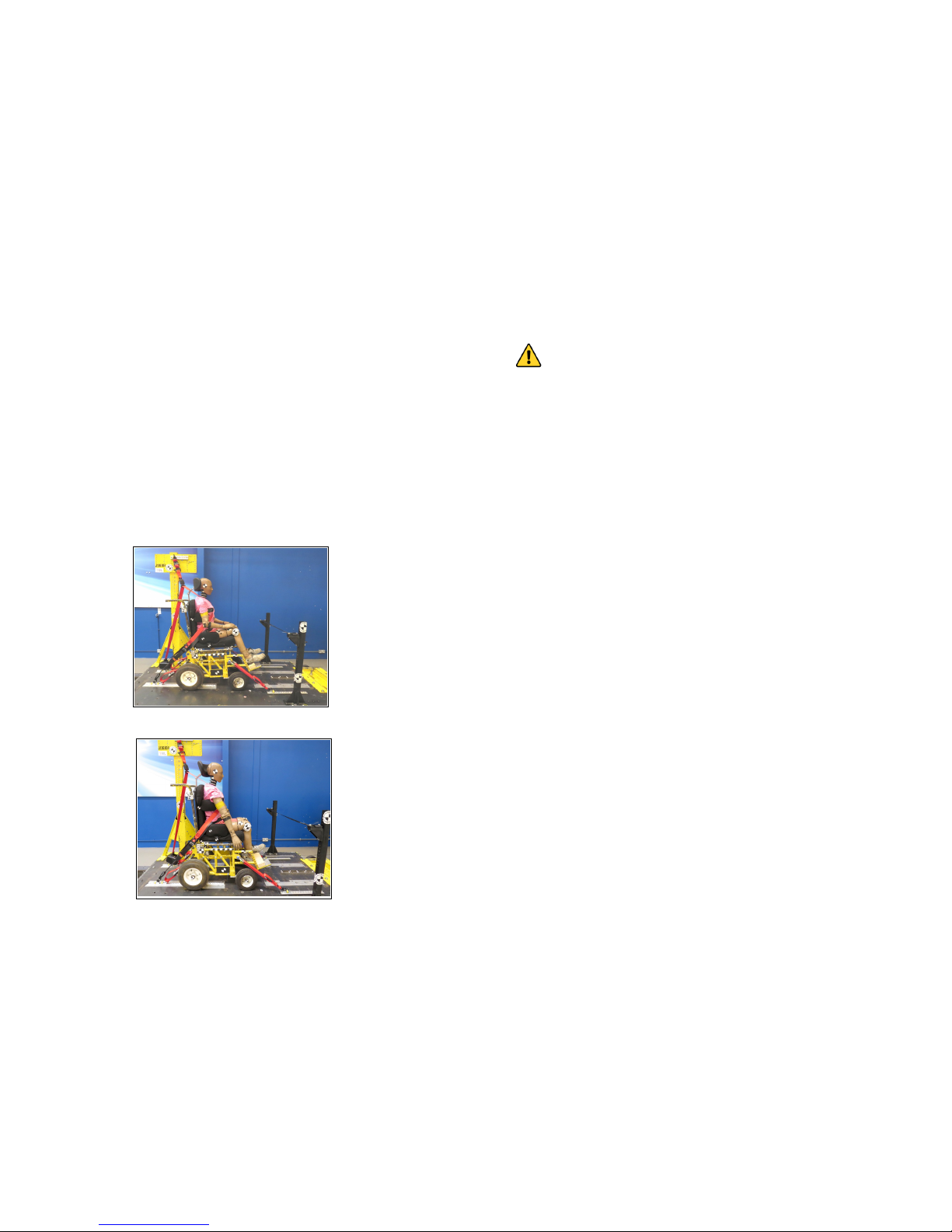
From the time of its initial conception, the caddy Seating System has undergone
rigorous strength testing and quality inspections, including successful “Crash
Testing” to ISO 16840-4 standard using a 50Kg ATD.
In view of the wide range of wheelchairs into which the caddy Seating System
can be interfaced, the pictures in this manual may not depict identically the
components supplied, or the location positions of installation for your specific
application. They are intended however, for general guidance purposes only and
to assist a suitably qualified person to install and adjust a complete caddy
Seating System.
RMS Ltd reserves the right to change, without notice, the design, methods of
manufacture, or any materials used in the construction of the caddy Seating
System, where it considers such changes will serve to improve the product
quality, or become necessary to meet any changes in device legislation.
Should the reader have any concerns regarding the installation, set-up,
adjustment, or use of the caddy Seating System, please contact the RMS Ltd.
Technical Help-Line on 01795-477280.
CONTENTS Page
Introduction 2
Safety Guidelines 3
Component Identification 4
Initial Installation:- 5
Seat and Backrest Identification (Positive Locking style) 6
Seat and Backrest Identification (Standard style) 7
Seat Base Installation (Using lock & Latch interfacing) 8
Installing Lock & Latch 8/9
Seat Base Installation (Fixed/Bolt-on Interface) 10/11
Backrest Installation (Positive Locking style) 12/13
Backrest Installation (Standard style) 13
Backrest Remove/Refitting and Angle Adjustment 14
Backrest Height Adjustment 15
Pelvic Supports 15 and 19
Lateral Thoracic Supports 16
Accessory Tricep Pads and Shoulder Pads 17
Accessory Headrest and Mounting 18
Alternative Pelvic Supports and Accessory Knee Adductors 19
Accessory Leg Abductor (Pommel) 20
Upholstery Care and Maintenance 21
Transportation 22-24
Warranty Statement 25
General Information, Product Maintenance and
Inspection Record 26
2
27
USER / CARER NOTES

26
GENERAL INFORMATION
Your caddy Seat Base serial Number is: …………………….........…
Your caddy Backrest serial number is: ……...…………..........……
Date of Supply: ………………..........………
Supplied to: …………………………………………………….....….…….
…………………………………………………….....………….
.………………………………………………………......………
PRODUCT MAINTENANCE
For safety reasons, the manufacturer recommends that components such as
the Seat Base Brackets, Lock and Latch Interface Brackets, Backrest
Mounting Brackets, Headrest Mountings, Pelvic Support Mountings, Thoracic
Support Mountings, Abductor and Adductor Mountings are checked for security at
annual intervals. Inspection frequency should be increased accordingly for heavy
users.
Any defects should be reported to the appropriate authority, with any repairs
being carried out using genuine original equipment replacement parts, available
direct from RMS Ltd.
(Also refer to Upholstery Maintenance section on pages 21).
INSPECTION RECORD
DATE INSPECTED
BY
COMMENTS SIGNED
3
SAFETY GUIDELINES
Due to the various activities that a wheelchair user has to perform, RMS
recommends that, prior to issuing the caddy Seating System and the
wheelchair into which it is to be interfaced, this manual, together with any
wheelchair manufacturer’ User Guide, should be studied by all relevant
persons to ensure that all instructions, procedures and warnings are
carefully observed and understood.
Prior to commencing the installation of a caddy Seating System, the
surrogate wheelbase should be placed on a level non-slip surface with the
parking brakes applied.
For correct support and user comfort, it is strongly recommended that the
initial installation and adjustments are carried out by a suitably qualified
person.
The maximum occupant capacity of a complete caddy Seating System for
transportation purposes, when interfaced into a suitably tested wheelchair
with a seat width up to 17", is 50Kg.
As the installation of a caddy Seating System may raise or position the user
further forward in their wheelchair, an appropriate stability test should be
carried out prior to final commissioning.
After the caddy Seating System has been initially adjusted to suit the
individual user, any settings should not be subsequently affected by the
removal and refitting of the Seat Base or Backrest to allow the wheelchair to
be folded. However, care should be taken not to impact adjustable
components whilst the Seat Base or Backrest is removed from the wheelchair
as this could affect their original pre-set position.
To accommodate any changes in user growth or postural positioning, it is
recommended that the user be checked at regular intervals by a suitably
qualified person, to ensure that adjustable components are correctly set to
suit the user’s current requirements.
Carers should ensure correct utilisation of any positioning Straps or
Harnesses, as failure to do so could result in injury to the user. It is
recommended that any postural Straps or Harnesses being used, are the first
items to be secured when the user enters the seat and the last items to be
released before exiting.
Worn or damaged upholstery can lead to hygiene contamination, cause
injury to the user and, in some cases, fail to support the user correctly.
Regular inspections of all upholstery should be made and any defects should
be reported to the relevant authority for rectification as soon as possible.
Ancillary devices, such as the Headrest, positioning Straps and Harnesses,
Knee-block or Pommel should be checked for security on a daily basis.
The wheelchair parking brakes should always be applied before attempting to
transfer the occupant, removing or refitting the caddy Seating System or
making any adjustments.
Never hang heavy objects on the caddy Seating System or any part of the
wheelchair, as this could seriously affect the overall stability.

The caddy Seating System —Component Identification
4
RMS positive-locking
“Swing-Away”
Lateral Supports
with removable,
washable Covers
Lock & Latch
Interfacing
System
Width Adjustable
Pelvic Supports
with removable,
washable Covers
Multi-adjustable
Headrest
with removable,
washable Cover
Padded Backrest
Cushion
with removable,
washable Cover
Optional
Flat or Ramped
Cushion
with removable,
washable Cover
Sacral Pad
with removable,
washable Cover
Seat Depth
Adjustment
Panel
Fig. 1
WARRANTY STATEMENT
Every effort is made by RMS Ltd to ensure that your caddy Modular
Adjustable Seating System is manufactured to the highest standards and
supplied to the specifications as detailed on the prescription.
The supply of our quality products is backed by the company’s ISO 9001
–2015 Quality Management System and CE Marking declaration.
The caddy Modular Seating System is supplied with a manufacturer’s
warranty covering faulty materials or workmanship, for a period of twelve
months from the date of dispatch from our factory.
In the unlikely event of a warranty claim being necessary, the failed part
must be returned to the manufacturer, or the manufacturer’s approved
repairer, for inspection. The failed part may then be repaired or replaced at
the manufacturer’s discretion or that of their approved repairer.
In the latter case, any displaced parts must be returned to the manufacturer
for inspection.
Any part, component or accessory, repaired or replaced during the twelve
month warranty period, will continue to be covered for the balance of the
warranty period only.
As unusually high rates of wear on this device, or its ancillary parts, may be
caused by the user’s clinical condition, the manufacturer may consider this
to be beyond its control. Therefore, items such as Upholstery may only be
considered for repair or replacement under the terms of the product
warranty where a failure is clearly attributed to a manufacturing, material or
fabric defect.
With the exception of modifications and /or alterations carried out by the
manufacturer, to meet the clinical needs of the user, any attempt to change
the design or modify the construction of the caddy Modular Seating
System in any way, will invalidate the product warranty and the
manufacturer’s CE marking declaration.
For further assistance with any matters relating to the product warranty or product Technical
Information, please contact the RMS Ltd Technical Help-line on 01795-477280.
25

Occupant Restraint Considerations:
A prescription should specify the type of occupant restraint required in a vehicle,
i.e. a lap and diagonal belt or full harness. The amount of upper body control that
the user has during normal vehicle movement should be taken into account.
“Normal” movement includes, braking and cornering, which have considerable
effect on persons with limited upper trunk control.
Some wheelchair users for example, may be able to maintain an upright posture
when using the wheelchair indoors, but not whilst travelling in a motor vehicle.
Such considerations apply equally to lower limb amputees and users in
supportive seating units who may also have limited upper body control.
**********
Example pictures from the successful caddy testing to ISO 16840-4
PRE-TEST
POST TEST
24
5
INITIAL INSTALLATION
IMPORTANT NOTES:
The caddy Seating System is supplied assembled and ready to be
interfaced onto the intended surrogate wheelchair. However, the installer
should note that some adjustment of both Seat and Backrest Support
Brackets may be necessary to ensure correct interfacing.
The installer should also note that at the time of despatch from the RMS
factory, none of the Backrest or Seat Base Support Brackets have been
fully and finally tightened. This has been done to allow the installer ease
of correctly positioning the interface brackets to suit the intended
surrogate base.
It is therefore, the responsibility of the installer to ensure that all
Interface Mounting and Component Screws and Nuts are correctly
tightened, before handover to the user. (This does not apply to caddy
Seating Systems interfaced with a surrogate base at the RMS factory).
Where the caddy Seating System is supplied by RMS Ltd., together with a
surrogate wheelbase, the following installation instructions may not
apply, as the interfacing and mounting brackets will normally be pre-set at
the RMS factory prior to delivery. Adjustable components may also be pre
-set to the required specification, where the necessary information was
stated on the device prescription.
Before commencing installation, the surrogate wheelchair should be
vacated and placed on a suitable level non-slip surface, with the parking
brakes applied.
For ease of installation, both side-arms should be removed wherever
possible.
Any references to left or right, relate to positions as viewed from being
seated in the wheelchair facing forwards.
The basic weight of a “Standard Specification” caddy Seating System to
suit a 43cm (17”) seat width wheelchair is 11.5Kg (25.3lbs)

6
Headrest Mount
with Locking
Thumb Screw
Lateral Support
Mounting Screws
with alternative
mounting positions
Backrest Support
Brackets
Positive Locking
Stem—Backrest to
Seat Base
Alternative mounting
positions for Backrest
Support Brackets
Upper Harness
mounting points
Mounting positions for
Pelvic Belt and Lower
Harness Straps
Securing Screws for
Backrest Height
Adjustment Panel
Backrest Support
Bracket Fixings
Front Seat Support
Bracket attachment
Screws (a)
Rear Seat Support
Bracket attachment
Screws (a)
Pelvic Support
Mounting Screws
3 Seat Support
Bracket
Width Adjustment
Locking Screws (b)
Width and Depth
Adjustable
Seat Support
Brackets
Seat Depth
Adjustment Panel
Securing Screws
Backrest Positive
Locking Catch
fixing points
Abductor (Pommel)
fixing points
Positive Locking Seat Base viewed from Underside
Fig. 3
Fig. 2
Maximum
Extension
Line
Positive Locking Backrest Panel viewed from Rear
Upper Backrest
Support Pins
Accessory Headrest
mounted on Angle
Adjustable Stem c/w
Height pre-set Collar.
Risk analysis for Wheelchair Transportation:
A comprehensive risk assessment is essential, taking into account the
user’s requirements and the type of transport they plan to use.
Potential risk areas:
The user being transferred to a fixed vehicle seat.
The wheelchair/seating unit being transported as unoccupied luggage.
The user occupying a wheelchair/seating unit during transportation.
Ability of the WTORS to hold the wheelchair and/or seating unit together with
the user during vehicle movement or in the event of an impact.
Effects of normal vehicle manoeuvres, such as braking, accelerating and
cornering on the wheelchair user.
Effects of the occupant restraint on the user, both in normal vehicle
movement and on impact.
Effects of the seating unit, wheelchair and / or any accessories being used, on
the action of a vehicle anchored occupant restraint in an impact.
Suitability of any interface that connects the seating unit to the wheelchair.
Postural support or belt/harness that is not sufficiently strong to withstand
the force of an impact.
Requirements for the use of a headrest to restrict the rearward movement of
the head during vehicle motion or impact.
The effect on other passengers if the user, wheelchair/seating unit or
accessories were to become detached during impact.
Wheelchair Security:
Although it may initially appear that the wheelchair and occupant are just one unit
to be restrained, the reality is that they are independent of each other yet the
forces created in their restraint will interact with each other.
As a result, it is extremely important that restraint of the wheelchair, does not
occur through the occupant and their restraint system, in a crash situation.
This now means that the wheelchair, often weighing-in at around 100 Kg, (for an
electric powered model) and deigned to be very mobile, must now become as
close as possible, to being a fixed seat, secured using a restraint system which is
independent from the occupant restraint system.
This system should be to the wheelchair manufacturers recommendations as it
will be of the type that the wheelchair was successfully crash tested with and
therefore proven to be suitable for that application.
The wheelchair must also be secured in such a way that it cannot tip over,
collapse or break-up causing injury to the occupant or other passengers in the
transporting vehicle.
[cont]
23

TRANSPORTATION
The caddy Seating System has been successfully Crash Tested to ISO
16840-4 (Seating Devices for use in Motor Vehicles), interfaced with an
approved surrogate test base. However, this does not imply and is not
intended to imply in any way, that the caddy Seating System is suitable for
transporting an occupant in a motor vehicle, other than with the caddy
Seating System being correctly interfaced with a surrogate wheelbase of a
type and model which has been successfully Crash Tested and meets the
requirements of ISO 7176-19.
The transporting vehicle MUST also be suitably equipped with wheelchair
and occupant restraint systems compliant with ISO 10542.
Under No Circumstances should any part of a transportation restraint
system, be attached directly to the caddy Seating System.
Whilst provision is made on the caddy Backrest for attaching a postural
positioning belt or harness, which should still be utilised as normal during the
transportation period, these support devices should NEVER be used as the
sole method of occupant restraint during transportation.
General information regarding the Transportation of Wheelchairs,
Seating Systems and their Occupants
The information given in this section is intended for guidance only. Any figures and
standards quoted are correct at the time of printing but may be subjected to change or
update in the future, as a result of ongoing product testing and experience gained
by those involved in both the Care and Transportation fields.
There are over 750,000 wheelchair users in the UK. Although thousands travel in
motor vehicles every day, very few problems are reported.
However, in the small number of injuries and fatalities recorded, investigations
have revealed that the cause is rarely attributed to a piece of faulty equipment.
The majority are the result of inappropriate, inadequate or incorrectly used
equipment, which can pose as much a risk to wheelchair users as a vehicle
impact.
The main areas where problems are identified :
Lack of communication between the parties involved, notably with transport
service providers before a wheelchair/seating unit is prescribed.
Lack of comprehensive risk analysis for users.
Lack of clear product information for users, carers and transporters.
Inadequate transportation information and training for users, carers,
prescribers, service providers and drivers.
Inappropriate, incomplete or misused, wheelchair tie-down systems (WTORS).
Inappropriate occupant restraint systems.
Incorrect use of tail lifts and ramps.
Wheelchairs blocking gangways and exits during transportation.
Transportation of unoccupied powered and non-powered wheelchairs without
being correctly secured. [cont]
22
7
Headrest Mount
with Locking
Thumb Screw
Lateral Support
Mounting Screws with
alternative
mounting positions
Backrest Support
Brackets
Backrest with
Tongue to interface
with Slot in Seat
Base
Alternative mounting
positions for Backrest
Support Brackets
Upper Harness
mounting points
Mounting positions for
Pelvic Belt and Lower
Harness Straps
Securing Screws for
Backrest Height
Adjustment Panel
Standard Backrest Panel viewed from Rear
Backrest Support
Bracket Fixings
Pelvic Support
Mounting Screws
3 Seat Support
Bracket Width
Adjustment Locking
Screws (b)
Receiver Slot
For Backrest
Tongue
Abductor (Pommel)
fixing points
Front Seat Support
Bracket attachment
Screws (a)
Rear Seat Support
Bracket attachment
Screws (a)
Width and Depth
Adjustable
Seat Support
Brackets
Seat Depth
Adjustment Panel
Securing Screws
Standard Seat Base viewed from Underside Fig. 4
Fig. 5
Upper Backrest
Support Pins
Accessory Headrest
mounted on Angle
Adjustable Stem c/w
Height pre-set Collar.

8
SEAT BASE INSTALLATION (Positive Locking and Standard Seats)
(Using Lock & Latch Interface method)
The caddy Seating System should only be installed by a suitably qualified
person.
Hexagon Keys 3,4 & 5mm and Flat Blade Screwdriver.
Disconnect and remove any original seating upholstery from the surrogate
wheelbase. (Methods may vary according to make and model).
Temporarily place the caddy Seat
Base Panel centrally in its intended
position on the wheelbase seat rails,
ensuring there is sufficient clearance
around any cross braces and seat rail
support saddles.
To adjust the Seat Support Brackets,
either forwards or rearwards, these
are secured by two Hex-drive screws
(a) Figs. 2 & 4, in each Support Bracket
*.
It may also be necessary to adjust the
Hook Brackets inwards or outwards on
each side to ensure correct contact
with the seat rails. These are secured by three Hex-drive grub-screws (b) Figs.
2 & 4 in each Hook Bracket **. *Using a 4mm Hex-key, slacken screws (a) on
each Support Bracket and **3mm Hex-key for the grub-screws (b) in the Hook
Brackets.
Re-position Brackets as required and re-secure all screws sufficient to prevent
any movement.
Seat Depth Adjustment Panels are provided as standard, Fig.6, to allow for
user growth or possible asymmetrical requirements, (see Figs.2 & 4 for
retaining screw positions). Seat Cushions therefore, will normally be to
the same dimensions as the Base Panel. However, special individual needs
may require an alternative Cushions. Please contact RMS sales.
INSTALLING LOCK & LATCH
Before removing Seat Base from wheelchair, lightly
mark seat rails at the back edge of rear Support Hooks
and front edge of the forward Support Hooks See Fig.7.
[Cont]
Fig.6
Latch Lock
Individual Seat Depth Adjustment Panels
Access to Seat
Support Bracket
attachment
screws is from
the underside
21
UPHOLSTERY CARE and MAINTENANCE
Unless otherwise requested, your caddy Seating System will be finished
in 100% Polyester, 3mm “Spacer” fabric.
Alternative surfaces may be textured or smooth (reversed).
Zip-removable covers enable easy removal, for cleaning or machine washing.
The “Spacer” fabrics have the following qualities:-
Flame Retardant to BS5852-2006 Ign. source 5 Crib 5 and meet or exceed
BSEN1021—1&2
Anti-Bacterial / Anti Fungal i.e. will not support microbial or fungal growth including
Salmonella, E Coli and MRSA.
Waterproof —Water or oil
Breathable —Moisture vapour permeable.
General Fabric Care
Use of a vacuum cleaner or soft brush, to remove dust and solid particles,
together with frequent wiping with a damp cloth, will to help to maintain the
appearance of the fabrics.
Spillages should always be removed as quickly as possible with an absorbent
dry cloth.
Minor Soiling can normally be removed with a clean damp cloth.
Water Based Stains can be cleaned using mild liquid detergent with warm
water. Use cold water for stains produced by bodily fluids, then rinsed
thoroughly, followed by drying with a clean absorbent cloth.
Light Steam Cleaning can be carried out in situ, ensure all areas are
completely dry before reuse.
Machine Washing with care @ 40°. Covers must NOT be turned inside-out
and any zips should be fully closed. Remove from machine as soon as the
wash cycle has finished.
DO NOT DRY CLEAN
Line Dry ideally the upholstery should be “Line Dried” do NOT Tumble Dry.
See Symbols below.
NOTES:
All soap residue must be thoroughly rinsed out of all fabrics, as it can attract
further stains.
All stains caused by bodily fluids, should be removed immediately.
As with all fabrics, stains that are left in situ for over 24 hours will have set and
will become increasingly difficult to remove.
Always pre-test cleaners on a hidden area of fabric to test for colour-fastness
and texture before proceeding with cleaning.

20
Accessory LEG ABDUCTOR (Pommel)
INSTALLATION and ADJUSTMENT
4mm Hexagon Key
The caddy Leg Abductor Figs.18 & 19 is intended for use as a device to
assist with user positioning and offers an angle adjustable vertical stem, with
a quick release fold down mechanism, thus avoiding the need for the device
removal during transfers.
The Abductor should be mounted to the upper front surface of the pre-drilled
Seat Base Board and may be attached, where access allows, by screws inserted
upwards from the underside into threaded key washers as Fig.18.
Where underside access is limited, it may be necessary for the screws to be
inserted downwards from the top into a single retaining plate with two threaded
holes (these are available from RMS sales). Depth adjustment of the Abductor is
therefore made at this point, Fig.18.
Depth adjustment of the Abductor Pad can also be made at the Pad attachment
point to it’s mounting bracket, Fig.19.
Height and angle adjustments can also be made by using a combination of
adjustment pivot points, Fig.18.
To fold the Abductor assembly either downwards or upwards, fully depress the
RED Lock-Release button Fig.19 and fold to the required locked position.
Fig.18 Fig.19
Angle
adjustment
pivot
points
Depress RED
Lock-Release
button to fold
Adductor
up or down
Depth
adjustment
Depth
adjustment
9
With the screws removed from the Lock and Latch Brackets, install both Lock
Brackets onto the seat rails (one each side). Locate each Lock Bracket with
the rear edge of the clamp in line with the previously marked front Support
Hook position. With locating lugs uppermost and pointing rearwards as Fig.7a,
install clamping screws and tighten sufficient to maintain the Bracket positions
on the seat rails.
Install the Latch Brackets onto the seat canvas rails and locate against the
previously marked position as Fig.7. Re-install clamping screws and tighten
clamps just sufficient to lightly maintain their position but still allowing their
movement if required. Pull each locking plunger rearwards until it clicks into
the unlocked position Fig.7b.
Re-install Seat Base Panel by raising the rear edge to approximately 15
whilst locating the front Support Brackets under each Lock Bracket. With the
Seat Panel resting on the seat rails and pushed fully forward, slide Latch
Brackets with the locking plunger uppermost, forwards until the clamps just
lightly contact the rear Seat Support Hook Brackets then back by 2mm Fig.7c.
To confirm correct bracket positioning, it is recommended that a careful test by
removal and refitting of the Seat Base Panel is carried at this stage.
Fully tighten all Lock & Latch clamping screws sufficient to maintain their
positions on the Seat Rails.
Lock
Bracket
Latch
Bracket
Seat Support
Hook Brackets
Clamping
Screws
Front
Latch Unlocked for Seat
Installation or Removal
Latch in
Locked position
Front Hook
Bracket located
Mark Seat Rails
Fig.7
Fig.7a Fig.7b Fig.7c

SEAT BASE INSTALLATION (Fixed/Bolt-on Interface method)
As positioning and methods of attachment for a fixed seat base may vary
according to the make and model of intended surrogate wheelchair, the
information detailed below should be used as general guidelines only.
Therefore, the caddy Seating System should only be installed by a suitably
qualified person.
Hexagon Keys 4 & 5mm, 10mm Spanner/Socket.
Power Drill with drill bit to suit the diameter of the mounting screws supplied
with seat unit.
Where a fixed Seat Board is already in place on the wheelchair, it is
suggested that this be removed and used as a template for drilling the
caddy Seat Base Board. As the O/E Seat Board may be secured to the
wheelchair seat frame by either four or six screws it is recommended that
the caddy Seat Board be secured by the same number of screws.
Disconnect and remove any original seating upholstery from the surrogate
wheelbase (methods may vary according to make and model).
Initially it is recommended, that the caddy Seat Unit be temporarily placed on
the surrogate wheelchair for the installer to gain a better understanding of
where the caddy should best be finally positioned.
Disconnect and remove the O/E Seat Board and place this over the caddy
Seat Base Board to mark the drilling positions for attaching to the wheelchair
frame. (Temporary removal of the individual Seat Depth Adjustment Panels may
be necessary prior to drilling)
Drill the appropriate number of holes required through the caddy Seat Base
Board, then replace the Seat Base Board onto the wheelchair to confirm correct
drilling alignment with the wheelchair frame.
[Cont]
10
M6 Mounting
screws with
washers Mounting
screws
with M6 nuts
and washers
Fig.8bFig.8a Spacers may
be required
19
Accessory ADJUSTABLE PELVIC SUPPORTS and KNEE ADDUCTORS
INSTALLATION and ADJUSTMENT
Whilst supplied with “Fixed” Straight style Pelvic Supports as standard,
alternative mounting brackets are also available (see the caddy prescription
form QMF100) for details and can be mounted to the Seat Panel as per the
“Fixed” style. These will enable each Support to be positioned inboard by
2.5cm or 5cm. Alternative brackets are available from RMS Sales.
When replacing Pelvic Support brackets on Seat Units with sufficient clearance
under the seat, the mounting screws can be accessed from the underside by
tilting or raising the Seat Base.
NOTE: The brackets DO NOT have to
be removed where the Pads only, are
being replaced, as the Pad to bracket
retaining screws and nuts are easily
accessed with the Pad covers removed.
Remove both screws from each
mounting bracket and retain the
threaded Lock Plates.
The new brackets can be attached to
the upper surface of the Seat Base by
inserting the screws from the underside
of the Seat and screwing into the
threaded Lock Plates as Fig.27.
Where Knee Adductors are being installed for the first time, the method of
attachment may vary according to the amount of underside access available
to the Seat Base. For normal installation, i.e. Good access, the retaining
screws should be installed from the underside and screwed into the threaded
Lock- Plates supplied, ensuring the key ways locate correctly into the slots in
the brackets before fully tightening.
Alternatively, where only limited access is available, the bracket retaining
screws may be installed through the slots in the brackets, downwards into the
threaded Lock Plates on the underside of the Seat Panel.
The Pads can be attached to the new brackets using the screws supplied and set
to the required position before fully tightening.
Adjustment of the bracket positions can be made both forwards and backwards
as well as laterally, just by slackening the retaining screws and moving to the
required position via the slots provided in the Seat Base and the Pad mounting
brackets. Retighten all screws sufficient to prevent any movement.
IMPORTANT NOTE: Users of Supportive Seating and associated devices,
should be regularly checked in areas of contact, for redness of skin, abrasions
and pressure sores etc.
Fig.27
Knee Adductor Pads
Pelvic Support
Pads
Lock
Plates

Accessory HEADREST and MOUNTING
INSTALLATION and ADJUSTMENT
Arange of ball mounted Headrests, with angle adjustable stems, is available
for use with the caddy Seating System and requires an appropriate mounting
bracket to be fitted to the rear face of the Backrest Panel. The Panel is pre-
drilled to accept various mounting brackets available from RMS Ltd.
(The Mounting Boss L4-P44 shown in Fig.25, is capable of accepting both 13mm
and 16mm standard square Headrest Stems).
3 & 4mm Hex. Keys. 13mm Spanner.
As installation of a Headrest Mount requires
access to the front and rear of the Backrest
Panel, the user should be removed from the
seat unit.
Temporarily remove the Backrest Upholstery
from the Backrest Panel.
From the rear of the Backrest, slacken both
securing screws for the Backrest Height
Adjustment Panel, refer to Figs.3 & 5 and
raise Panel to it’s highest point to expose the
Headrest Mounting holes required.
(If using the Mounting Boss shown in Fig.25,
the four centre holes will be required).
Remove all four screws from the Mounting
Boss and hold the Boss assembly against the rear of the Backrest Panel with the
13mm square receiver hole at the top when a 13mm Headrest Stem is being
used, or 16mm hole at the top if using a 16mm square Stem. Insert each of the
previously removed four screws, through
from the front of Backrest Panel and
screw into the Mounting Boss.
Fully tighten all screws evenly sufficient
to prevent any movement.
Re-secure the Backrest Height
Adjustment Panel in it’s previous position
and re-attach the Backrest Upholstery.
Headrest height adjustment can be made
at both the Mounting Boss and Link pivots
Fig.25. Forward adjustment can also be
made at the Link pivot points.
Swivel adjustment can be made at the
Headrest Ball Mount Fig.26.
With the Headrest Stem inserted into the
Mounting Boss to the required position,
fully tighten the Locking Thumb-screw
Fig.26. The Height Pre-set Collar, when set, enables the Headrest to be refitted to
the same height after each removal.
18
Fig.25
Fig.26
Link
Pivot
Points
Headrest
Mounting
Boss
L4-P44
Locking
Thumb-
screw
Headrest
Ball
Mounting
Height
pre-set
Collar
Where there is limited access to the underside of the Seat Base Board and
to improve the adjustability of the Pelvic Supports and/or Knee Adductors
(where fitted), it is advisable before finally attaching the Seat Base Board, to
reverse the mounting screws i.e. to be inserted from the top of their
brackets and screwing into the their threaded plates which will now to be
located on the underside of the Seat Base Board, with the threaded bosses
pointing downwards.
Finally attach the caddy Seat Base Board to the wheelchair seat frame using
the screws supplied, with large washers under their heads and where possible
on the underside of the frame and secure with Nylock nuts.
Although spacers are supplied for use between the caddy Seat Base Board
and the mounting points on the wheelchair frame Figs. 8a & 8b, these may
not be required for all applications
Please liaise with RMS technical team, should any difficulties arise at this stage.
11

12
BACKREST INSTALLATION (Positive Locking Backrest)
This model of caddy Backrest is equipped with a Positive Locking mechanism,
which enables the Backrest Panel to be easily removed or installed as required.
The upper area of the Backrest is secured to the wheelchair, by Support Brackets
attached to the Backrest Panel and Upper Backrest Mounting Lock-Pin Brackets,
which are securely clamped to the wheelchair backrest frames. Fig.9.
SEAT UNIT only SUPPLIED
Backrest Installation
Hexagon Keys 3,4 & 5mm
To assist the installer with locating
the most suitable mounting positions
for the Upper Backrest Mounting Lock-
Pin Brackets, the Backrest Panel
should be placed against the
wheelchair backrest frames, with the
Positive Locking Stem Fig.3, fully
engaged into the Positive Locking
Mechanism, Fig.9.
A minimum 50mm of straight
Backrest Frame will be required
to enable the Lock-Pin Bracket
Mounting Clamps Fig.10. to be
attached correctly attached.
Separate the two halves of the
Clamps by removing both clamping
screws. Install the Lock-Pin Brackets
onto the wheelchair backrest frames as
Fig.10 and secure the Clamps just
sufficient to maintain their positions on
the frames. DO NOT fully tighten at
this stage.
Positive Locking
Mechanism Catch
Backrest Support
Brackets
Upper Backrest
Mounting
Lock-Pin Brackets
Fig.9
Safety
Locking-Pin
Pull to remove
Clamping
Screws
Fig.10
Lock-Pin Bracket
Mounting Clamps.
17
Accessory TRICEP PADS and SHOULDER PADS
INSTALLATION and ADJUSTMENT
Both Tricep Pads and Shoulder Pads are available in two sizes, 75x100mm and
100x150mm. The Tricep Pads are supplied with 25mm adjustment links, whereas
Shoulder Pads will be supplied with 50mm adjustment links. The devices are
intended to give additional support to the user’s shoulder areas and the muscle
areas at the rear of the upper arms.
2.5mm and 4mm Hexagon Keys
The Backrest Panel is manufactured with a matrix of holes to enable the
attachment of accessories to either the front or rear face, see Fig. 23.
Both Tricep and Shoulder Pad
Mounting Brackets, should be
attached to the rear face, with
their attachment screws installed
from the front.
The installer will need to locate
the ideal positions to suit the
user’s requirements for the
Mounting Brackets, taking into
account the current position of
the Lateral Supports the
wheelchair sidearms.
The wheelchair should be
vacated prior to commencing
installation.
Detach and remove the upper section of the
Backrest Upholstery.
To mount the Tricep or Shoulder Pads their
Brackets should be attached to the rear face of
the Backrest Panel using the screws provided
through the appropriate holes from the outer two
lines of pre-drilled holes on each side, screwing
into the pre-tapped holes in the Brackets. As
there is no adjustment at this point, fully tighten
screws to prevent any movement.
Lateral rotational adjustment can be made by the Adjustment Links, by peeling
back their fabric covers to gain access to the two main pivot screws. With the
correct positions achieved, fully retighten the main pivot screws. The Pad
positions can then be securely locked by tightening all Link locking grub-screws
Fig.24. NOTE: There are two grub-screws on the top and bottom links.
Refit link covers.
The wheelchair sidearms may also require re-positioning.
Shoulder
Pads
Tricep
Pads
Fig.23
Main pivot
screws
Link locking
grub-crews
Backrest
Panel
Link cover temporarily removed
Fig.24

16
LATERAL (THORACIC) SUPPORTS
(Standard Fixed and accessory Swing-away and Wrap-around styles)
INSTALLATION and ADJUSTMENT
4mm Hexagon Key
The caddy Backrest Panels are designed with pre-drilled holes to enable
Lateral Supports to be fitted at various heights, Fig.20.
When factory fitted, the Supports will be positioned as requested on the
original prescription. However, these positions may need to change due to
user growth, positioning needs or changes required in seasonal clothing.
Swing-away and Wrap-around styles, feature a positive locking method in
the forward position, which is released by depressing a Lock-Release button
on each device, Figs.21 & 22.
The curved Wrap-around style lateral pads are produced with tension
straps, connected and adjustable via a buckle.
To raise or lower the Lateral Support Mountings, it will be necessary to remove
both securing screws from each Mounting, these are located at the rear of the
Backrest Panel, Fig.20. Reposition the Mountings using the alternative fixing
points provided and using the original screws and special key-way nuts.
NOTE: When tightening the securing screws, care should be taken to ensure the
key-way nuts are located correctly in the Mounting Bracket slots.
Fully tighten the securing screws
Width adjustment of the Lateral Supports with the user seated can easily be
carried out, by slackening the retaining screws, adjust as required and retighten
screws just sufficient to prevent any movement.
All Lateral Supports have zipped-removable, washable covers, refer to
washing instructions on page 21.
Lateral Support
mounting screws
with alternative
fixing points.
Fig.20 Fig.21
Fixed and Swing-away
Wrap-around and Swing-away
Swing-away Lock Release
Tension strap with buckle
Fig.22
13
With both Safety Locking Pins removed
from their Brackets, Fig.11, position each
Backrest Support Bracket in turn, with it’s
Locating Pin inserted into a Lock–Pin
Bracket.
By holding these Brackets in a level
position against the Backrest Panel
Fig.12, will indicate to the installer which
screw holes should be used to attach the
Brackets to the Backrest Panel.
Attach the Backrest Support Brackets to
the rear of Backrest Panel using two
M6 x 20 Hex. drive countersink screws
provided for each side.
These should be inserted from the front of
the Panel and screwed into the Threaded
Lock Plates which should be positioned
inside the Backrest Support Brackets as
Fig.12.
Before fully tightening these screws, and
those located in the Lock-Pin Bracket
Mounting Clamps Fig.10, ensure the
Backrest is correctly positioned with the Positive Locking mechanism fully
engaged Fig.8 and both Upper Support Pins Fig.11 are fully engaged in their
Mountings.
Tighten all screws sufficient to prevent any movement.
Reinstall both Safety Locking-Pins.
BACKREST INSTALLATION
(Standard Backrest)
The Standard caddy Backrest differs
from the Positive Locking model, by
virtue of the shaped tongue on the
lower edge Fig.5, which is designed to
engage with the slot located at the rear of
the Seat Panel Fig.4.
Therefore, installation of the Backrest
Support Brackets and Upper Mounting Lock
- Pin Brackets, is the same as detailed on
the previous page and above covering the
Positive Locking model, also shown in
Fig.13.
Fig.12
Threaded
Lock Plates
Fig.11
Upper Support
Pins fully engaged
in Lock-Pin
Bracket Mounting
Clamps.
Backrest Support
Brackets
Upper Backrest
Mounting
Lock-Pin Brackets
Fig.13

14
REMOVING and REFITTING BACKREST (Positive Locking models)
With the wheelchair vacated:-
1.[Remove both Lock-Pins] 2. [Release Positive Lock Catch] 3. [Lift Backrest clear of wheelchair]
On Standard models, operations 1 and 3 only will be required.
Refitting will be the reverse of the above, ensuring that the Positive Locking
Stem fully engages into the Catch and the Upper Support Pins engage
correctly into their Upper Mounting Brackets. Refit both Lock-Pins.
When refitting the Standard Backrest, ensure the Upper Support Pins
engage correctly into their Upper Mounting Brackets at the same time as
the tongue locates correctly into the Seat Panel. Refit both Lock-Pins.
BACKREST ANGLE ADJUSTMENT 5mm Hex. Key
The Backrest angle in relation to the Seat Base, is adjustable from +5˚ to
–15˚, however, this amount of adjustment may vary slightly dependant on
the position of the Seat Base on the wheelchair
seat rails. Where necessary, this may also require
adjustment via the Lock and Latch positions if the
Backrest angle has not been achievable with the
Seat in its initially fitted position.
To change the Backrest angle, slacken the two
angle locking screws Fig.14, on each side,
located through slots in the Backrest Support
Brackets. Reposition the Backrest Panel as
required and retighten all screws sufficient to prevent any movement.
NOTE: In some cases, the installer may find it necessary to re-attach the
Upper Backrest Lock-Pin Brackets in reversed positions. This will require
changing the Brackets from side to side and re-attaching to the Backrest Support
Brackets. This will have the effect of supporting the Backrest further forwards or
further backwards from its previous position.
Backrest
angle
locking
screws
Fig.14
Op.1 Op.2 Op.3
15
BACKREST HEIGHT ADJUSTMENT 4mm Hex. Key
To enable the Backrest
height to be adjusted, a
Height Adjustment Panel
is attached to the upper
front face of the Backrest
Panel by two screws
inserted through the rear
of the Panel, screwing into
threaded key washers
Figs. 3, 5 and 15.
Detach and remove Upper
Backrest Upholstery.
Slacken both screws and re-position Height Adjustment panel as required.
Retighten screws just sufficient to prevent any movement.
Reattach Upper Backrest Upholstery level with the top
of the Backrest.
Where the Backrest has been raised, it may be
necessary to install the additional infill panel, between
the main Upholstery and Sacral Pad Fig.16
(Infill panel supplied and packaged with the new
caddy Seat Unit).
PELVIC SUPPORTS 4mm Hex. Key
These are adjustable individually, laterally
by 35mm each also forwards or rearwards.
Access to their mounting screws is from the
underside of the Seat Unit, Figs.2 and 4. on
removable seat units and from the upper
face of fixed seat bases.
Slacken both screws on each Pelvic
Support Bracket, reposition as required
and retighten screws sufficient to prevent
any movement.
Whilst the caddy will be supplied with the Pelvic Supports set to the pelvic
width as stated on the initial prescription form, these may still require slight
adjustment at final hand-over, due to changes in growth or seasonal clothing.
NOTE: Two alternative mounting brackets are available from RMS sales
where the required pelvic width cannot be achieved with the current
brackets. Where alternative or replacement brackets are required, please
refer to page 19.
Fig.15
Fig.16
Insert
Infill Pad
Fig.17
Pelvic Support securing
screws may be on top
of bracket or on
underside of seat
Table of contents
Other RMS Wheelchair manuals