RMS Gill 4 Seating System EDTION TWO 2012 User manual

The
New
Seating System
The Perfect Partnership
USER
MANUAL
EDTION TWO
2012
4
Discovery Edition

INTRODUCTION
The Gill 4 Seating System is the result of experienced, thoughtful design
and rigorous testing over 16 months of field trials, in-house testing and frontal
impact testing. The Gill 4 Seating System was successfully tested to ISO 16840-
4 at the Transport Research Laboratory in March 2012.
Many adjustable features have been built into the Gill 4, enabling it to
become an extremely versatile seating system, available in three sizes.
With two backrest options available, the Gill 4 Seating System has been
designed specifically by our engineers, to meet the known wide range of
demands placed on postural positioning seat units.
The “Dynamic” Backrest option, offers the ability to absorb the type of
thrusting forces, placed on it during user extensor spasms, with a uniquely
designed absorbing system, which is variable to suit individual user
requirements.
The “Fixed” Backrest option, offers the same supportive capabilities as a normal
rigid back seat unit, but with angle adjustment available to 90, 95 and 100
degrees.
RMS Ltd reserves the right to change without notice, the design, methods
of manufacture, or raw materials used in the construction of the Gill 4 Seating
System, where it considers such changes will serve to improve the product
quality, or become necessary to meet any changes in device legislation.
Should the reader have any concerns regarding the installation, set-up,
adjustments, or use of the Gill 4 Seating System, please contact the RMS Ltd
Technical Help-line on 01634-578881.
Contents
Gill 4 Seat Plan ....................................................... 3
Safety Guidelines ....................................................4
Initial Installation ..................................................... 5
Inserting Gill 4 into Discovery wheelbase .............. 6
Adjusting the Gill 4 Seating System ...................... 7
Seat Depth and Sidearms ..................................... 7
Sacral Support Panel and Pelvic Supports ........... 8
Thoracic Supports ................................................. 9
Headrest ................................................................10
Notes regarding Backrest adjusting ..................10-11
Footrests ............................................................... 11
Anklesures installation and use .............................12
Anti-thrust Seat depth adjustment .........................13
Abductor (Pommel) Install and Adjust ..............14-15
Upholstery and Cleaning .......................................16
Transportation information ................................17-20
Technical Data ..................................................20-21
Warranty Statement .............................................. 22
General Information .............................................. 23
Product Maintenance ............................................ 23
2

Both Fixed and Dynamic Seat Units are supplied as standard, with the following
features:-
Quick-release Interface.
Depth-adjustable Anti-thrust Seat Cushion.
Width adjustable full-length fixed Pelvic Supports.
Width adjustable swing-away Thoracic Supports.
Adjustable Sacral Support.
RMS type “D” Headrest.
RMS PB003 Pelvic Belt.
Machine washable, removable Upholstery.
Optional Accessories available:
Footrest Mounting Frame c/w multi-positional Footplates, Anklesure Foot
Controls, Sidearms with height and depth adjustment, Leg Abductors, Various
Harnesses and Pelvic Belt options. Clear plastic or Ply laminate Contoured
Trays (for use with G4-05-01 Sidearm Kits)
3
Gill 4 SEAT PLAN
RMS Type “D” Headrest
with angle-adjustable stem
Removable
Footrest Support
Frame
Padded
Pelvic Supports
Positive Locking
Swing-away
Thoracic Supports
Depth-adjustable
Backrest Support
Dynamic
Thrust Absorber
Removable and
Machine washable
Upholstery
Adjustable Anti-
Thrust Cushion
Height and
Depth-adjustable
Sidearms
Adjustable
Sacral Support
Fig. 1

4
SAFETY GUIDELINES
Due to the various activities that a wheelchair user has to perform, RMS Ltd
recommends that, prior to issuing the GILL 4 Seating System and the
wheelchair into which it is to be interfaced, this manual, together with any
wheelchair manufacturer’ User Guide, should be studied by all relevant
persons, to ensure that all instructions, procedures and warnings are carefully
observed and understood.
For correct support and user comfort, it is strongly recommended that the
initial installation any adjustments and final hand-over are carried out by a
suitably qualified person.
The maximum occupant capacity of a complete GILL 4 Seating System for
transportation purposes, when interfaced into a wheelchair with a seat width
up to 17”, is 50Kg (7.8 stones).
As the installation of a GILL III System may raise or position the user further
forward in their wheelchair, an appropriate stability test should be carried out
prior to final commissioning.
After the GILL 4 Seating System has been initially adjusted to suit the
individual user, any settings should not be affected subsequently, by the
removal and refitting of the Seat Unit to allow the wheelchair to be folded.
However, care should be taken not to impact adjustable components whilst
the Seat Unit is removed from the wheelchair, as this could affect their
original pre-set position.
To accommodate any changes in user growth or postural positioning, it is
recommended that the user be checked at regular intervals by a suitably
qualified person, to ensure that adjustable components are correctly set to
suit the user’s current requirements.
Carers should ensure correct utilisation of any positioning Straps or
Harnesses, as failure to do so could result in injury to the user. It is
recommended that any Postural Straps or Harnesses being used, are the
first items to be secured when the user enters the seat and the last items to
be released before exiting.
Worn or damaged upholstery can lead to hygiene contamination, cause
injury to the user and, in some cases, fail to support the user correctly.
Regular inspections of all upholstery should be made and any defects
should be reported to the relevant authority for rectification as soon as
possible.
Ancillary devices, such as the Headrest, positioning Straps and Harnesses,
Kneeblock or Pommel should be checked for security and positioning on a
daily basis.
The wheelchair parking brakes should always be applied before attempting
to transfer the occupant, removing or refitting the GILL 4 System or making
any adjustments.
Never hang heavy objects on the GILL 4 Seating System or any part of the
wheelchair, as this could seriously affect the overall wheelchair stability.

INITIAL INSTALLATION
The information contained in this User Manual, relates to the Gill 4 Seating
System being interfaced with an appropriate sized Otto Bock Discovery
wheelbase, fitted with an M30 Parallel Adapter Frame.
IMPORTANT NOTES:
The Gill 4 Seating System and Discovery wheelbase, when supplied as
a “G4—Disco Package”, will be assembled ready to be interfaced
together. However, the installer should note that whilst the Gill 4 and
Discovery will leave RMS Ltd set to the specifications detailed on the
original assessment prescription, some minor adjustments of either the
Seat or Backrest components may be necessary to ensure the final
correct seating support is achieved.
Any reference to Left or Right in this manual, will refer to the Left or
Right side when sitting forward facing in the Seat Unit.
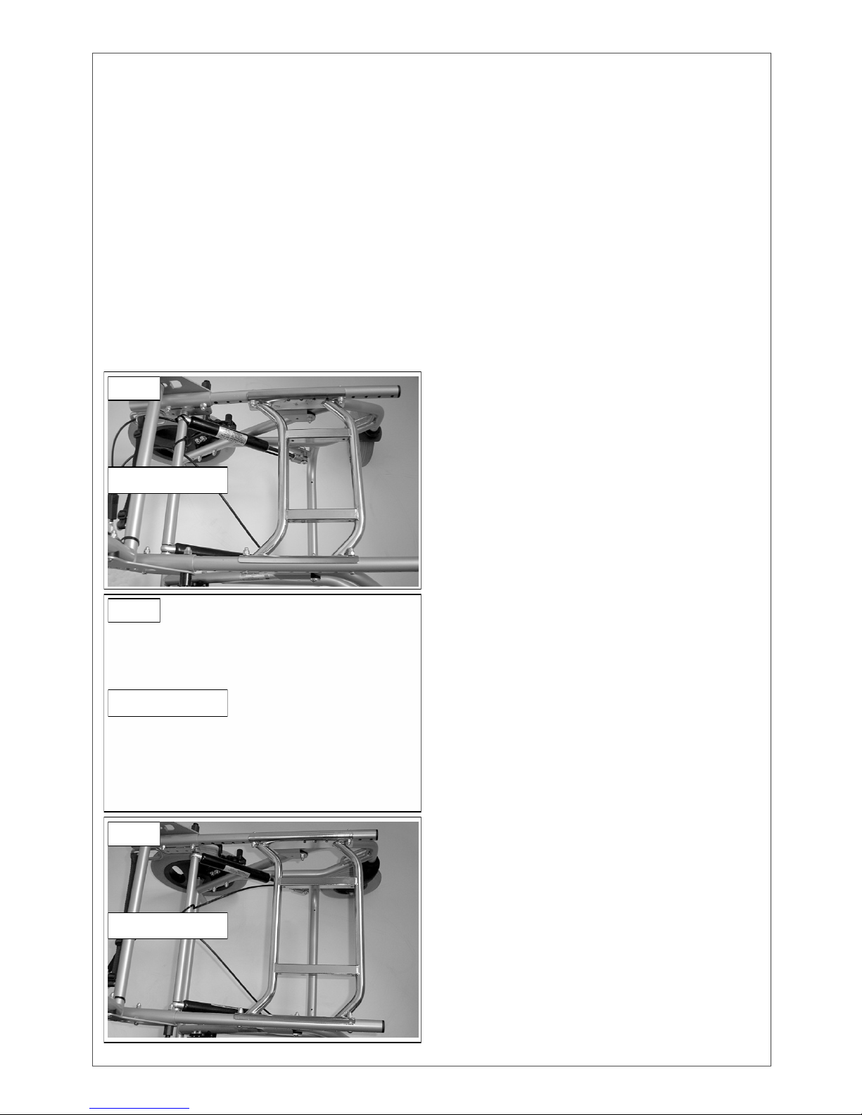
Gill 4—Discovery Compatibility:
Where a Gill 4 Seating System is
supplied for use with a currently owned
Discovery wheelbase, it will be
necessary to ensure that the correct
*Interface Parallel Adapter, as detailed
below, is securely installed onto the
wheelbase in the most suitable position.
Gill 4 size 1—36cm Discovery only.
Use RMS G4 size 1 interface with
*M30 Parallel Adapter HR32048200
Gill 4 size 2—40cm Discovery only.
Use RMS G4 size 2 interface with
*M30 Parallel Adapter HR32048300
Gill 4 size 3—45cm Discovery only.
Use RMS G4 size 2 interface with
*M30 Parallel Adapter HR32048400
NOTE:
Whilst Figs.2, 3 and 4 give examples of
the Parallel Adapters fitted to three sizes
of Discovery wheelbases, some slight
adjustment of these may be necessary
where stability becomes an issue
created by changes in the user’s
disability.
5
Fig. 2
Fig. 3
Fig. 4
36cm Discovery
40cm Discovery
45cm Discovery

INSERTING the Gill 4 into the DISCOVERY WHEELBASE
With the Interface Adapter securely fitted and both wheelbase parking brakes
applied, recline the wheelbase Backrest/Push Handles rearwards to allow
better manoeuvrability during installation of the Seat Unit.
Position the Gill 4 Seat Unit on the Discovery wheelbase, directly over the
Interface Adapter.
Introduce the Gill 4 Seat Unit into the Interface Adapter, by raising the front of
the seat (1) Fig.5, approximately 100mm (4") from horizontal.
This will allow the Seat Unit to slide rearwards (2) Fig.5 and enable the
Interface Rear Locator section to engage under the rear frame of the
Interface Adapter Fig.6.
Lower the Gill 4 Seat Unit (3) Fig.5, until
the Interface Lock Catches engage Fig.6.
REMOVAL of Gill 4 from Discovery Wheelbase
Should it become necessary to remove the Gill 4 from it’s surrogate base,
ensure the wheelbase parking brakes are fully applied.
Recline the wheelbase Backrest/Push Handles rearwards
Whilst supporting the Gill 4 Backrest with one hand, release both Interface
Locking Catches by compressing the release levers Figs.7 & 8.
Lift the Gill 4 Seat Unit at the front by approximately 100mm (4") then lift the
Seat forwards and upwards clear of the wheelbase.
6
Interface Lock Catches
Interface Rear Locator
1
2
3
Fig. 5
Fig. 6
Interface Catches Unlocked
Unlock Interface Catches
Fig. 8
Fig. 7

ADJUSTING the Gill 4 SEATING SYSTEM
All Gill 4 Seating Systems, will be supplied by RMS Ltd, to the specifications
detailed on the initial prescription. However, further initial adjustments may be
necessary at the time of delivery, to suit individual requirements.
Periodic adjustments may also be necessary to allow for changes in the user’s
disability, user growth and the user’s need for changes in seasonal clothing.
Seat Depth adjustment Tool Required: 4mm Hexagon Key.
The Seat Depth is adjusted
by slackening three screws
on each side of the lower
Backrest Mountings Fig.9
and moving the Backrest
forwards or rearwards
equally, within the seat rail
tracks.
After achieving the required
seat depth, retighten all
screws on both sides
sufficient to prevent any
movement.
NOTE: Following the
Backrest adjustment, it may
be necessary to move the Pelvic Belt Mountings and / or Sidearm Frame
Mounting positions.
A 4mm Hexagon Key is required to adjust the Pelvic Belt position, Fig.10. Flip-
up the Belt Mounting cover, to expose the mounting screw. Slacken only, adjust
Belt Mounting position and retighten screw, sufficient to prevent any movement.
The initial Pelvic Belt length should also be adjusted at the Mountings before re-
securing the Mounting cover.
The standard Pelvic Belt is of the “single-pull” type which is finally adjusted after
connecting the Main Buckle, by simply pulling the D-ring belt.
A 5mm Hexagon Key is required to
adjust the Sidearm Frame Mounts.
Remove the black Height Locking
Screws to access the front Sidearm
Mounting screw.
Slacken both screws, move Frame
to required position and retighten
both screws, sufficient to prevent any
movement.
Secure Sidearm at required height,
by refitting and tightening the black
Height Locking Screw Fig.10.
7
Fig. 9
Fig. 10 Pelvic Belt Mount
lift flap to gain
access to screw
Sidearm
Mounting Screws
Height Locking
Screw
Backrest Mounting
Screws

SACRAL SUPPORT PANEL
Tool Required: 4mm Hexagon Key.
The Sacral Support Panel is adjustable forwards of the Backrest Panel for up to
25mm. Access to the mounting screws is from each side of the Backrest
Support Brackets Fig.11, with the slotted Sacral Support Panel Mountings
located on the inner face of the Backrest Support Brackets at the rear of the
Backrest Panel Fig.12. To adjust the Sacral Support Panel, slacken only the
two screws on each side as indicated in Fig.12, re-position the Sacral Support
Panel as required, equally on each side and re-tighten all four screws sufficient
to prevent any movement.
Pelvic Supports
Tool Required: 4mm Hexagon Key.
The Pelvic Supports are attached to the
Sacral Support Panel by Mounting
Brackets and are both height and width
adjustable. Access to their mounting
screws is from the rear of the seat unit
Fig.13.
To adjust the Pelvic Supports laterally,
slacken both Support Mounting screws
and slide Support sideways to the
required position. Alternative mounting
holes are also available for each
Support, enabling the Support Mounting
to be re-positioned a further 25mm
laterally and vertically. Care should be
taken to retain the threaded Key
Washers located on the forward face of
the Mounting Brackets, Fig.15.
8
Sacral Support
Mounting Screws
Sacral Support
Panel Mounting
Fig. 12
Fig. 11
Fig. 13
Pelvic Support Mounting Screws
Thoracic Support Mounting Screws

LATERAL (Thoracic) SUPPORTS
Tool Required: 4mm Hexagon Key.
The Gill 4 Seating System is supplied
with “Swing Away” Thoracic Supports
as standard Fig.14. These have a
positive locking mechanism in the
forward pointing position.
Depressing the green button on the
Mounting Brackets, will release the
locks and allow the Support Pads to
swing away during user transfers.
The Thoracic Supports are both width
and height adjustable, with access to
their mounting screws at the rear of the
Backrest Panel Fig.13.
Initial width adjustment can be made by
slackening both mounting screws on
each Mounting Bracket and moving
each Pad assembly sideways to the
required position. Retighten all screws
sufficient to prevent any movement.
A matrix of mounting holes in the Backrest Panel Fig.13, enables the Thoracic
Supports to be raised or lowered at 25mm intervals and to position the Supports
25mm further outwards, when initially mounted using the inner rows of holes.
To make these adjustments, both screws on each Mounting Bracket must be
removed. Care should be taken to retain the threaded Key Washers located on
the forward face of the Mounting Brackets, Fig.15.
Relocate the Thoracic Supports to their new
position by holding the Support, together with one
Key Washer, over the intended position and
inserting a mounting screw through the Backrest
Panel from the rear. Engage the screw a few
threads into the first Key Washer, before adding
the second Key Washer and screw. Tighten both
screws evenly, sufficient to maintain their position,
but not fully tightened as further minor lateral
adjustment maybe necessary with the user
seated. Repeat with the opposite Support.
When the correct positioning is achieved, fully
tighten both screws on each Thoracic Support
Bracket, sufficient to prevent any movement.
9
NOTE: The RMS Dynamic Harness shown,
are available as optional accessories.
Fig. 14
Key
Washers
Fig. 15
Thoracic Support Lock Release

The HEADREST
The Gill 4 Seating System, is fitted as standard, with an RMS Type D Headrest,
incorporating a Ball—mounted, Angle Adjustable Stem with height pre-set collar
and a two screw fixing Backrest Mount.
Tools Required: 3, 4 and 5mm Hexagon Keys. 13mm Spanner.
Correct positioning of the Headrest
to suit individual requirements, is
normally achieved by a
combination of adjustments.
Refer to Fig.16
The Ball—Mount built into the
Headrest, enables the Headrest to
swivel around the ball. The three
screws should be slackened to
allow correct positioning and
always retightened evenly to
maintain the Headrest position.
The Angle Adjustable Stem has
two pivot points, both of which
should be slackened to enable the
Headrest to be moved in a forward
or rearward direction. Fully tighten
both M8 nuts sufficient to prevent
any movement.
The overall height of the Headrest and Stem assembly, is locked-off by the
Headrest locking Screw located on the Stem Mount attached to the Backrest.
To enable the Headrest to be refitted to the same height each time after
removal, the Stem is supplied with a height pre-set collar. This should be locked
in place by it’s grub-screw, when all other Headrest positioning adjustments
have been completed. The Headrest should therefore, always removed and
refitted as an assembly.
10
Angle
Adjustment
Joints
Headrest
Ball Joint
Headrest Stem
Mount Headrest Stem
Locking Screw
Headrest
Height
Pre-set Collar
Fig. 16
Gill 4 Dynamic Backrest Units only.
IMPORTANT NOTES:
The Gill 4 Dynamic Seat Unit, will be supplied with the appropriate Pressure
Absorbing Backrest setting, as prescribed at the intended user’s assessment.
The Backrest Pressure Absorbing action, should be reviewed at regular
intervals, as any changes in the user’s disability may require alternative
Pressure Absorbers.
WARNING: Inappropriate changing of the Dynamic Pressure Absorbers,
could reduce the overall effectiveness of the Backrest, creating
premature wear. Therefore, changes to the initially prescribed setting,
should only be carried out by a suitably qualified person, following the
instructions enclosed with the alternative Pressure Absorber Kit,
available from RMS Sales. [Cont]

Gill 4 Fixed Backrest Units only.
Fixed Back Gill 4 Seat Units, will be supplied with the Backrest pre-set to the
angle requested on the initial prescription (90°, 95° or 100°). This angle should
only be changed by a suitably qualified person, following the instructions
enclosed with the alternative Angle Positioning Insert Kit, available from
RMS Sales.
FOOTRESTS (Optional)
Tools Required: 4 and 5mm Hexagon Keys.
The Footrest Frame assembly, complete with
multi-positional footplates mounted on a height
adjustable cross-frame is inserted into the front of
the Seat Rails and secured in place by a Ball
Locking Pin located at each side of the Seat
Fig.17. Removal, is by depressing the centre
button on each Locking Pin and fully withdrawing
both Pins. Slide the Frame assembly forwards,
clear of the Seat Unit.
Height adjustment of the
Footrests is made by
slackening both Cross
Frame Mounting Clamps
Fig.18, to allow the
Frame to be raised or
lowered to the required
height. Retighten all
clamping screws evenly,
sufficient to prevent any
movement.
The multi-positional
Footrests are angle
adjustable by their ability
to rotate around the
Cross Frame.
To change the angles or positions of the Footrests, slacken all four clamping
screws on each Footplate, rotate / re-position as required and re-tighten all
clamping screws evenly.
The Footrests may also be positioned either further forward or rearward of their
supplied central mounting position, by removing all clamping screws on each
Footrest and repositioning the Footrest over it’s clamp. All screws must be
tightened evenly to ensure maximum clamping on the Cross Frame and
sufficient to prevent movement.
11
Fig. 17
Fig. 18
Ball Locking
Pin
Footrest Cross Frame
Mounting Clamp
Footrest Mounting
Clamp Screws with
alternative
mounting positions

ANKLESURES (Optional)
Tools Required: 4mm Hexagon Key and 8mm Spanner.
RMS Anklesures, are devices intended for use to control unwanted foot
movements and are easily fitted to the Multi-positional Footrests recommended
for use with the Gill 4 Seating Systems.
Anklesures are available in five sizes and manufactured to suit left and right side
fitting. To ensure correct comfort
and to achieve their intended
purpose, it is recommended
they are fitted by a suitably
qualified person.
Installing Anklesures
Initially, two special Mounting
Bridges must be installed onto
each Footrest, as shown in
Fig.19, using the screws, nuts
and washers, supplied in the
Anklesure Kit.
Care should be taken not to
over-tighten the screws.
For ease of use when fitted, it is
recommended that the Tri-glide, through
which the ankle-band strap is routed,
and then pulled back on itself, should be
towards the inside of each foot as Fig.19.
To attach each Anklesure to its Mounting
Bridges, route the free end of each
vertical side strap, downwards on the
foot side of the Bridges, then under the
Bridges and back upwards on the
outside of the Bridges, then finally thread
the strap through its own Tri-glide as
Figs.20. These straps should be
adjusted with the user seated to ensure
correct positioning.
To use the Anklesures, open out each ankle-band sufficient to enable the user’s
foot to be placed inside. With the ankle-band strap routed through its Tri-glide,
pull the strap gently back on itself to achieve the correct contact and secure via
the Velcro panel.
Whilst correct positioning of the Anklesures will depend on the user’s
requirements, care should be taken not to over-tighten these devices.
12
Fig. 19 Tri-glide positioned on
inside of ankle band.
Left side shown.
Fig. 20
Side Straps
Mounting
Bridge
Routing
vertical straps
Secure via
Velcro

DEPTH ADJUSTABLE Anti-Thrust CUSHION
No Tools are required for this adjustment.
The Gill 4 Anti-thrust Seat Cushion has been specially designed to offer an
adjustable depth of anti-thrust shelf. Adjustment of 50mm is available with the
size One Gill 4, with 75mm available for the sizes Two and Three.
To adjust the anti-thrust shelf depth, remove the Seat Cushion from the Seat
Base-board Fig.21. Turn the Cushion upside-down and fully un-zip the fabric
Cover to expose the foam Cushion Pad Fig.22. Remove the Pad from its cover
and turn over with the anti-thrust shelf at the top.
NOTES:
Fig.(a) above, shows the initial Cushion Pad lay-out for the Gill 4, sizes Two
and Three. Fig.(b) shows the initial lay-out for the size One Gill 4.
A “Sun-Mate” foam panel is enclosed in a pocket below the upper surface
fabric of the Seat Cushion Cover, (Not Shown). DO NOT remove this foam
panel from the Cover, when carrying out adjustments.
Depth adjustment of the anti-thrust shelf is achieved by removing the 25mm
Velcro attached segments from the Base Pad and moving the larger top Pad (x)
forwards to achieve the required depth.
Refit the Seat Cushion Cover (both Zip pulls should finish at the rear of the
Cushion) and reinstall Cushion onto the Gill 4 Seat Base Board.
13
Fig. 21 Fig. 22
c dba 3 Segments 1 Segment removed All Segments removed2 Segments removed
(x) (x)
(x)(x)

LEG ABDUCTOR (Pommel) (Optional) INSTALLATION
Tools Required:
4mm Hexagon Key
The Gill 4 Pommel Fig.23, is intended
to assist with user positioning, by
offering adjustable, multi-directional
Pads, mounted on a height adjustable
vertical Stem and depth adjustable
horizontal Stem. The Pommel
assembly can be easily inserted into
it’s Pop-Pin type Receiver Mount,
located under the front of the Seat
Panel.
Where a Pommel is not supplied
initially, with the Gill 4 Seat Unit, a
Receiver Mount (Supplied with the
Pommel), must be fitted under the
Seat Panel. Lift the front of the Seat
Cushion to locate the two pre-drilled
holes at the front of Seat Panel
intended for this purpose, Fig.24.
Using the screws and threaded key
washers supplied, attach the Receiver
Mount centrally to the underside of the
Seat Panel, with the black Thumb Screw
towards the left-side of the Seat Unit.
Tighten both screws sufficient to prevent
any movement, ensuring that the
threaded key washers are correctly
located in their slots Fig.24.
The horizontal Stem is fitted with a spring
“Pop-Pin” that can be inserted into one of
four holes Fig.25. This combination
enables depth adjustment in 25mm
increments. 14
Fig. 24
Receiver
Mount
Vertical
Adjustment
Lock Nut
Black Locking
Thumb Screw
Pop-Pin
Release
Key
Washers
Fig. 23
Fig. 25
“Pop-Pin” with
Adjustment Holes
Cover for Pad
Adjustment
Mechanism

LEG ABDUCTOR (Pommel) PAD ADJUSTMENT
Tools Required: 3mm and 5mm Hexagon Keys and 13mm Spanner.
To ensure correct comfort and to
achieve its intended purpose, it is
recommended that this device be
adjusted by a suitably qualified
person.
Initially it will be necessary to remove
the Cover, Fig.23, from the Pad
Adjustment Mechanism.
To allow the Pommel Pads to be
suitably repositioned, slacken all pivot
point Pad Adjustment Mechanism
screws, Fig.26.
The “Finger” style mechanism enables
the Pads to be rotated around their
pivot points to achieve positions to
suit most requirements including
asymmetrical positioning.
All Pivot Point Screws should be
tightened sufficient to prevent any movement.
Refit Adjustment Mechanism Cover, with the plastic draw string lock button
towards the front. With the Cover snugly fitted, pull draw string tight and secure
lock button in place. IMPORTANT NOTE: As there is a potential for small
fingers to be trapped within an exposed “Finger” Mechanism, it is essential that
the Cover Fig.23, is correctly refitted after carrying out any adjustments.
Final height adjustment can be completed, by slackening the M8 Domed Nut
located at the bottom of the vertical Pommel Stem, Fig.24. Raise or lower the
Pommel upper Stem as required then retighten the M8 Domed Nut sufficient to
prevent any movement.
To remove the Pommel assembly from the Seat unit, Slacken the Black Locking
Thumb Screw Fig.24, depress the spring “Pop-Pin” and slide the Pommel
assembly forwards clear of the Seat Base.
To refit Pommel, depress spring “Pop-Pin” on the horizontal Stem to allow it to
enter the Pommel Mount. Slide Pommel Device rearwards until the spring “Pop-
Pin” engages into its locking hole in the side of the Receiver Mount. Re-secure
the Black Thumb Screw, sufficient to prevent any movement.
NOTE: Positioning of the Pommel components, should not be affected by it’s
removal and refitting, although safe storage of the device is strongly
recommended when removed from the Gill 4 Seat unit.
15
Pad Adjustment
Mechanism
Screws
Fig.26

UPHOLSTERY
Unless otherwise requested, your Gill 4 Seating System will be finished in two-
tone upholstery.
The main base colour material, will be of black 100% Polyester, 3mm “Spacer”
fabric, complemented by colour co-ordinated edging panels of 100% Polyester
Agua Libra fabric.
All upholstery items are easily removable, for cleaning or machine washing.
Both fabrics are:-
Flame Retardant to BS5852 Crib 5 and meet or exceed BSEN1021.
Anti-Bacterial / Anti Fungal i.e. will not support microbial or fungal growth
including Salmonella, E Coli and MRSA.
Waterproof —Water or oil
Breathable —Moisture vapour permeable.
General Fabric Care
Use of a vacuum cleaner or soft brush, to remove dust and solid particles,
together with frequent wiping with a damp cloth, will to help to maintain the
appearance of the fabrics.
Spillages should always be removed as quickly as possible with an
absorbent dry cloth.
Minor Soiling can normally be removed with a clean damp cloth.
Water Based Stains can be cleaned using mild liquid detergent with warm
water. Use cold water for stains produced by bodily fluids, then rinsed
thoroughly, followed by drying with a clean absorbent cloth.
Light Steam Cleaning can be carried out in situ, ensure all areas are
completely dry before reuse.
Machine Washing with care @ 40°. Covers must NOT be turned inside-out
and any zips should be fully closed. Remove from machine as soon as the
wash cycle has finished.
DO NOT DRY CLEAN
Line Dry ideally the upholstery should be “Line Dried” do NOT Tumble Dry.
See Symbols below.
NOTES:
All soap residue must be thoroughly rinsed out of all fabrics, as it can attract
further stains.
All stains caused by bodily fluids, should be removed immediately.
As with all fabrics, stains that are left in situ for over 24 hours will have set
and will become increasingly difficult to remove.
Always pre-test cleaners on a hidden area of fabric to test for colour-fastness
and texture before proceeding with cleaning.
16

TRANSPORTATION
The GILL 4 Seating System, complete with Interface, has been successfully
tested to ISO 16840-4 (Seating Devices for use in Motor Vehicles), whilst
interfaced on an approved surrogate test base.
However, this does not imply and is not intended to imply in any way, that the
GILL 4 Seating System is suitable for transporting an occupant in a motor
vehicle in any other way than with the GILL 4 Seating System being correctly
interfaced with a surrogate wheelchair of a type and model which has been
successfully tested in its own right, to meet the requirements of ISO 7176-19
(Wheeled mobility devices for use in Motor Vehicles).
The transporting vehicle MUST be suitably equipped with wheelchair and
occupant restraint systems compliant with ISO 10542.
Under No Circumstances should any part of a transportation restraint
system, be attached directly to the GILL 4 Seating System.
Whilst provision is made on the GILL 4 Backrest for attachment of an
ancillary Postural Positioning Harness, which, if fitted, should still be utilised
as normal during any transportation period, this positioning device should
NEVER be used as the sole method of occupant restraint during
transportation.
The standard recommended restraint system, Part Number Q-5001-T2, for
transporting the GILL 4 Seating System, the Occupant and Surrogate
Wheelchair as detailed above, is available from :
Q-Straint (Europe)
175 John Wilson Business Park, Whitstable, Kent CT5 3RB
Tel. 01227 773035 Fax. 01227 770035
This kit includes a complete set of four-point wheelchair restraints and three-
point occupant restraints.
If the intended transporting vehicle is not already fitted with Q-Straint anchorage
tracks, details of these can also be obtained direct from Q-Straint (Europe).
NOTE: Installation and use of all restraint systems should always be strictly as
per their manufacturers recommendations.
[Cont]
17

General information regarding Transportation
of Wheelchairs, Seating Systems and their Occupants
Please Note:
The information given in this section is intended for guidance only. Any figures and
standards quoted are correct at the time of printing but may be subjected to change
or update in the future, as a result of ongoing product testing and experience gained
by those involved in both the Care and Transportation fields.
There are over 750,000 wheelchair users in the UK. Although thousands
travel in motor vehicles every day, very few problems are reported.
However, in the small number of injuries and fatalities recorded,
investigations have revealed that the cause is rarely attributed to a piece
of faulty equipment.
The majority are the result of inappropriate, inadequate or incorrectly used
equipment, which can pose as much a risk to wheelchair users as a
vehicle impact.
The main areas where problems are identified :
Lack of communication between the parties involved, notably with transport
service providers before a wheelchair/seating unit is prescribed.
Lack of comprehensive risk analysis for users.
Lack of clear product information for users, carers and transporters.
Inadequate transportation information and training for users, carers,
prescribers, service providers and drivers.
Inappropriate, incomplete or misused, wheelchair tie-down systems
(WTORS).
Inappropriate occupant restraint systems.
Incorrect use of tail lifts and ramps.
Wheelchairs blocking gangways and exits during transportation.
Transportation of unoccupied powered and non-powered wheelchairs without
being correctly secured.
Forces Created in a Crash:
The “Crash Test” that wheelchairs, seating systems and restraint systems
undergo and have to satisfy, is a 30mph - 20g crash simulation.
This crash simulation represents a severe crash for a small vehicle like a family
car, a car derived van (M1 category) or a mini-bus up to 5 tonnes in weight (M2
category).
The crash test assumes that the deceleration rate of the vehicle, will create
forces where items of mass will weigh 20 times their normal weight.
(For example a 1Kg bag of sugar would effectively weigh 20Kg).
In comparison, this would mean that a 100Kg powered wheelchair will weigh 2
tonnes and an 85Kg occupant will weigh 1.7 tonnes.
[Cont]
18

Risk analysis for Wheelchair Transportation:
A comprehensive risk assessment is essential, taking into account the user’s
requirements and the type of transport they plan to use.
Potential risk areas:
The user being transferred to a fixed vehicle seat.
The wheelchair/seating unit being transported as unoccupied luggage.
The user occupying a wheelchair/seating unit during transportation.
Ability of the WTORS to hold the wheelchair and/or seating unit together with
the user during vehicle movement or in the event of an impact.
Effects of normal vehicle manoeuvres, such as braking, accelerating and
cornering on the wheelchair user.
Effects of the occupant restraint on the user, both in normal vehicle
movement and on impact.
Effects of the seating unit, wheelchair and / or any accessories being used,
on the action of a vehicle anchored occupant restraint in an impact.
Suitability of any interface that connects the seating unit to the wheelchair.
Postural support or belt/harness that is not sufficiently strong to withstand
the force of an impact.
Requirements for the use of a headrest to restrict the rearward movement of
the head during vehicle motion or impact.
The effect on other passengers if the user, wheelchair / seating unit or
accessories were to become detached during impact.
Wheelchair Security:
Although it may initially appear that the wheelchair and occupant are just one
unit to be restrained, the reality is that they are independent of each other yet
the forces created in their restraint will interact with each other.
As a result, it is extremely important that restraint of the wheelchair, does not
occur through the occupant and their restraint system, in a crash situation.
This now means that the wheelchair, often weighing-in at around 100 Kg, (for an
electric powered model) and designed to be very mobile, must now become as
close as possible, to being a fixed seat, secured using a restraint system which
is independent from the occupant restraint system.
The wheelchair must also be secured in such a way that it cannot tip over,
collapse, or break-up, causing injury to the occupant or other passengers in the
transporting vehicle.
The restraint systems should be to the wheelchair manufacturers
recommendations, as it will be of the type that the wheelchair was successfully
crash tested with and therefore proven to be suitable for that application.
[Cont]
19

Occupant Restraint Considerations:
A prescription should specify the type of occupant restraint required in a vehicle,
i.e. a lap and diagonal belt or full harness. The amount of upper body control
that the user has during normal vehicle movement should be taken into account.
“Normal” movement includes, braking and cornering, which have considerable
effect on persons with limited upper trunk control.
Some wheelchair users for example, may be able to maintain an upright posture
when using the wheelchair indoors, but not whilst travelling in a
motor vehicle.
Such considerations apply equally to lower limb amputees and users in
supportive seating units who may also have limited upper body control.
**********
TECHNICAL DATA
Seat Unit Weights:
Seat Unit Seat Unit c/w
Only Sidearms and Footrests
Size 1 11.9Kg 15.4Kg
Size 2 14.7Kg 18.1Kg
Size 3 16.9Kg 20.6Kg
Maximum User Weight for Transportation: = 50Kg
Maximum Seat Unit Dimensions:
The following dimensions are taken using the Gill 4 Seat Unit, removed from it’s
surrogate base and when fitted with the highest of three available Backrests.
The Seat Unit was positioned on a level surface, with the Headrest, Sidearms
and Footrest Frame removed.
Max. Height Max. Width Max. Depth
Size 1 640mm 500mm 460mm
Size 2 675mm 560mm 500mm
Size 3 735mm 600mm 600mm
Dynamic Backrests only:
The Dynamic Pressure Absorbers are available in three resistance levels.
For identification, these are colour coded as follows:-
Blue DX Low Resistance
Black DY Medium Resistance
Red DZ High Resistance
[Cont]
20
Table of contents
Other RMS Wheelchair manuals