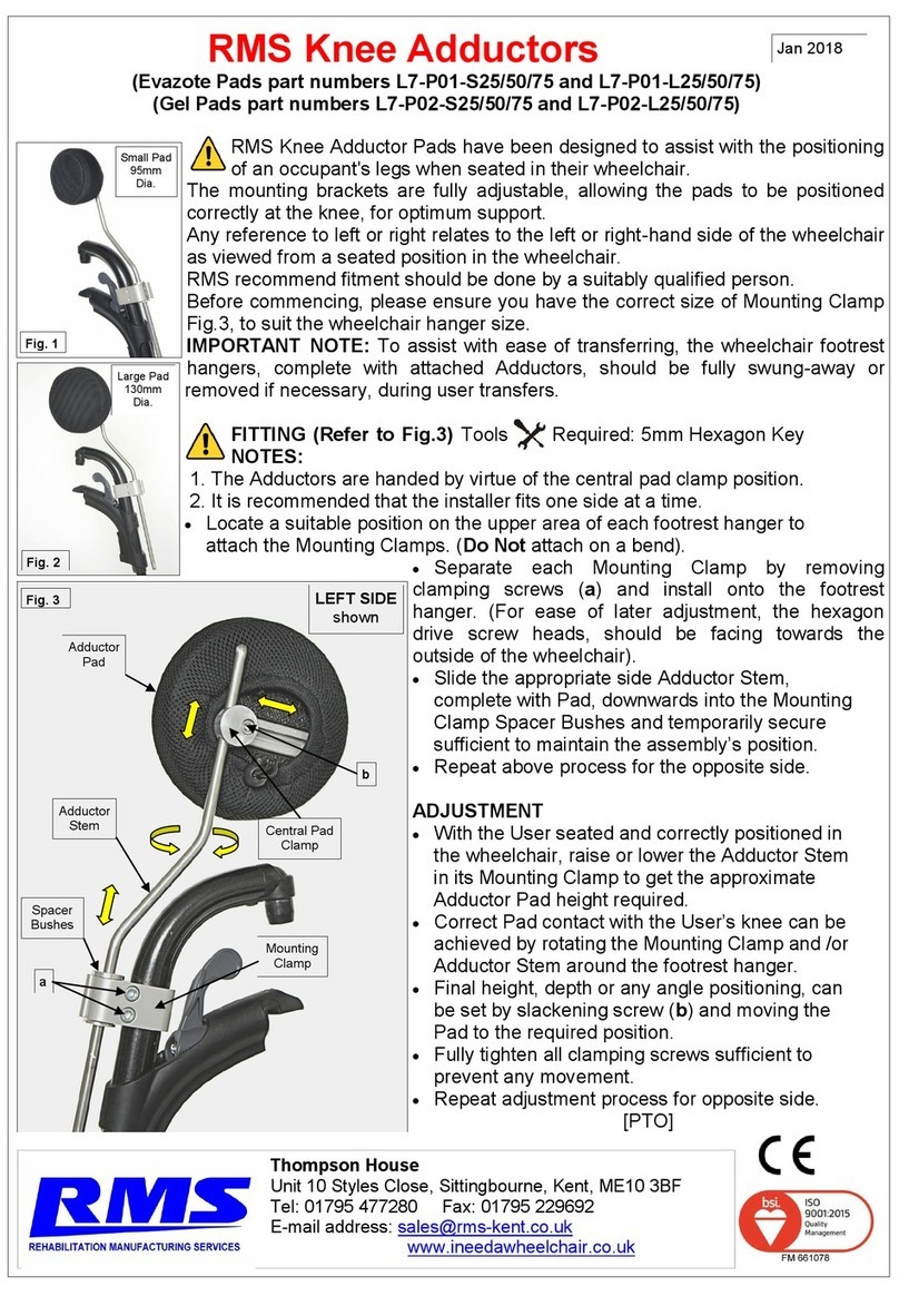
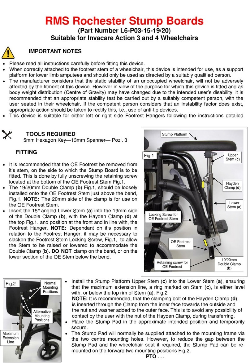
RMS L6-P03-15-19/20 Operation manual

RMS Rochester Stump Boards
(Part Number L6-P03-15-19/20)
Suitable for Otto Bock Start Wheelchairs
IMPORTANT NOTES
Please read all instructions carefully before fitting this device.
When correctly attached to the footrest stem of a wheelchair, this device is intended for use, as a support
platform for lower limb amputees and should only be used as directed by a suitably qualified person.
The manufacturer considers that the static stability of an unoccupied wheelchair, will not be adversely
affected by the fitment of this device. However in view of the purpose for which this device is fitted and as
body weight distribution (Centre of Gravity) may have changed due to the intended user’s disability, it is
recommended that an appropriate stability test be carried out by a suitably competent person, with the
user seated in their wheelchair. If the competent person considers that an instability factor does exist,
appropriate action should be taken to rectify this, i.e., use of anti-tip devices.
This device is suitable for attachment to left or right side Footrest Hangers.
FITTING
It is recommended that the Original Equipment Footrest
be removed from it’s stem, on the side to which the
Stump Board is to be fitted. This is done by fully removing
the retaining and pivoting screws, located at the bottom
of the OE Footrest Stem Fig.1.
The 19/20mm Double Clamp (b) Fig.1, should be loosely
installed onto the OE Footrest Stem just above the bend,
Fig.1. NOTE: The 20mm side of the clamp is for use on
the OE Footrest Stem.
Insert the 15° angled Lower Stem (a) into the 19mm side
of the Double Clamp (b), with the Hayden Clamp (d) at
the top and position at the front and in line with, the
Footrest Hanger. NOTE: Dependant on it’s position in
relation to the Footrest Hanger, it may be necessary to
slacken the Footrest Stem Locking Screw, Fig.1, to allow
the Stem to be raised or lowered to accommodate the
Double Clamp (b). DO NOT clamp on the bend, or on the
lower section of the OE Stem below the bend.
TOOLS REQUIRED
5mm Hexagon Key—13mm Spanner—Pozi. 3 Screwdriver
3/8 or 1/4 drive 10mm Socket with Bar or Ratchet.
Install the Stump Platform Upper Stem (c) into the Lower Stem (a), ensuring
that the maximum extension line, (a ring marked on Stem (c)), is either level
with, or ideally, 25mm below the top rim of the Lower Stem (a). Fig.2.
NOTE: It is recommended, that the clamping bolt of the Hayden Clamp (d),
is inserted through the Clamp from the inner face towards the outside and
the nut and washer added to the outer face. This is to avoid any possibility of
contact by the user with the nut of the Hayden Clamp, during transferring.
Place the Stump Pad in the approximate intended position and temporarily
secure the device just sufficient to maintain its position.
The Stump Pad will normally be supplied attached to the mounting frame via
the two centre mounting holes. However, to reduce the gap between the
Stump Pad and the wheelchair seat, if required, the Stump Pad can be re-
mounted on the forward two mounting positions Fig.2.
PTO …...
Locking Screw for
OE Footrest Stem
19/20mm
Double Clamp
(b) OE Footrest Stem
with Footplate
removed.
Lower
Stem (a)
Hayden
Clamp (d)
Upper
Stem (c)
Stump Platform
Fig.1
Standard
Mounting
Positions
Alternative
Mounting
Positions
Maximum
Extension Line is
indicated on
Upper Stem
Fig.2

ADJUSTMENTS
The following information is for guideline
purposes only and all final adjustments should
be made at the discretion of the installer, to
ensure the appropriate support is achieved for
individual user.
Height adjustment is possible at several points:-
Ideally, the Upper Stem “maximum extension
line” Figs.2 & 3, should be inserted into the
Lower Stem by at least 25mm. This will allow
the Stump Platform to be raised slightly if
required at a later date, without exceeding the
maximum extension line. Fully tighten the
Hayden Clamp, sufficient to prevent any
movement.
The OE Footrest Stem can be raised or
lowered within the Hanger by slackening the
Locking Screw Fig.3, located within the plastic
shroud covering the Footrest Hanger. Fully
tighten Locking Screw sufficient to prevent
any movement after adjustment.
The Lower Stem (a) Fig.3, can be raised or
lowered within the Double Clamp (b) after
slackening. After repositioning the Stem, re-
tighten both clamping screws evenly, sufficient
to prevent any movement.
With all adjustments completed, the Stump
Board Stems should be in line (front to rear)
with the OE Footrest Hanger.
USER INFORMATION
The Rochester Stump Board is intended for use as a Stump support device when permanently
attached to the Footrest Hanger of a wheelchair and should not be used for any reason, other
than it’s intended purpose. It has been designed to support a weight of 20Kg (44Lbs).
The user should never attempt to support their body weight on the Stump Platform as this could
cause the wheelchair to tip forwards.
To assist with ease of transferring, the Stump Board Platform is hinged, which allows the Platform
to be folded upwards to a vertical position see Fig.2. The Footrest hanger can also still be
swung away, or completely removed, with the Stump Board assembly attached.
The user or carer should always ensure that the Footrest Hanger is correctly locked into place on the
wheelchair, before using the Stump Board.
Security of the Stump Board assembly on the Footrest Hanger should be checked daily before use.
To ensure this device remains safe, serviceable and reliable throughout it’s period of use, RMS Ltd
recommends it be inspected for wear, damage and security of components at 4 monthly intervals
(For very heavy users the period between inspections should be reduced accordingly.
Any worn or damaged components should be replaced as soon as possible with original equipment
parts available from RMS Ltd.
Hygienic use of the Stump Platform is very important and should be cleaned and disinfected on a
regular basis with warm soapy water with a little disinfectant added, or a recognised upholstery
cleaner, using a damp cloth or sponge. Ensure the Stump Platform is completely dry before use.
Keep away from naked flames and sources of excessive heat.
For further information on this or any other products in the RMS range, please contact our Technical Help-line on 01795 477280
Lower Stem
Locking Screw
Insert Upper
Stem “maximum
extension” line
into Lower Stem
by at least 25mm.
Fig.3
Upper Stem
(c)
Hayden
Clamp (d)
Lower
Stem (a)
19/20
Double
Clamp (b)
OE Footrest
Stem
Dec 2021
Thompson House
Unit 10 Styles Close, Sittingbourne, Kent, ME10 3BF
Tel: 01795 477280 Fax: 01795 229692
E-mail address: sales@rms-kent.co.uk
www.ineedawheelchair.co.uk
Table of contents
Other RMS Wheelchair manuals
