RNA ESR 2500 User manual

Rhein-Nadel Automation 1 14.04.2014
VT-BA-ESR2500/2800-GB
Operating Instructions
Control Units
for Oscillating Drives
ESR 2500 / 2800
1

Rhein-Nadel Automation 2 14.04.2014
VT-BA-ESR2500/2800-GB
1Introduction 3
2General 5
3Saftey Regulations and General Warnings 7
4Installation 9
5Operation 14
6Technical Data 24
7Alarms 25
Declaration of Conformity
in terms of the Low Voltage Directive 2014/35/EU
and the EMC Directive 2014/30/EU
We herewith declare that the product is in conformity with the following provisions:
Low Voltage Guideline 2014/35/EU
EMC Directive 2014/30/EU
Applied harmonised standards: DIN EN 60204 T1
EN 61439-1
Comments:
Rhein-Nadel-Automation
--------------------------------
Managing Director
Jack Grevenstein

Rhein-Nadel Automation 3 14.04.2014
VT-BA-ESR2500/2800-GB
1 Introduction
1.1 Field of application
The control units of the ESR2500/2800 series are output regulators and frequency controllers for RNA
vibratory and linear feeder drives.
This document describes the operation, technical data and installation procedure of the ESR 2500/2800
models and their accessories offered in this product line.
1.2 Functional Description
This fully automatic control unit was developed to operate a bowl feeder or linear feeder.
The intelligent control system continuously checks the mechanical vibration of the feeder and uses this signal
to actively regulate the oscillation amplitude whilst making sure that the vibration stays exactly at the preset
amplitude, regardless of the conveyed load, ambient temperature and mains frequency, etc.
The frequency of the drive voltage is automatically regulated in a PLL control circuit, so that the feeder is
always operated under optimum conditions, i.e. exactly in the resonant range.
The control system adapts itself to the specific feeder via an automatic fine-adjustment process, through
which the often laborious procedure of mechanical adjustment ceases.
With these control units, vibratory bowl feeders with different mains frequencies can be operated without
having to change the magnets or having to be adjustedmechanically.
The control system has a self-protection which ensures that neither the conveyor magnets nor any other
components become overloaded. The operating parameters of all mechanical and electrical components are
constantly monitored. In the event of larger deviations, the monitoring function triggers alarm signals before
any serious consequences happen, i.e. it identifies defective springs or loose nuts before any damage can
occur.
In this control system, there are two sensor amplifiers with 24V DC.
In addition, there are two optocouplers and a relay output for status messages as well as an external enable
input with 24V DC for the remote control.

Rhein-Nadel Automation 4 14.04.2014
VT-BA-ESR2500/2800-GB
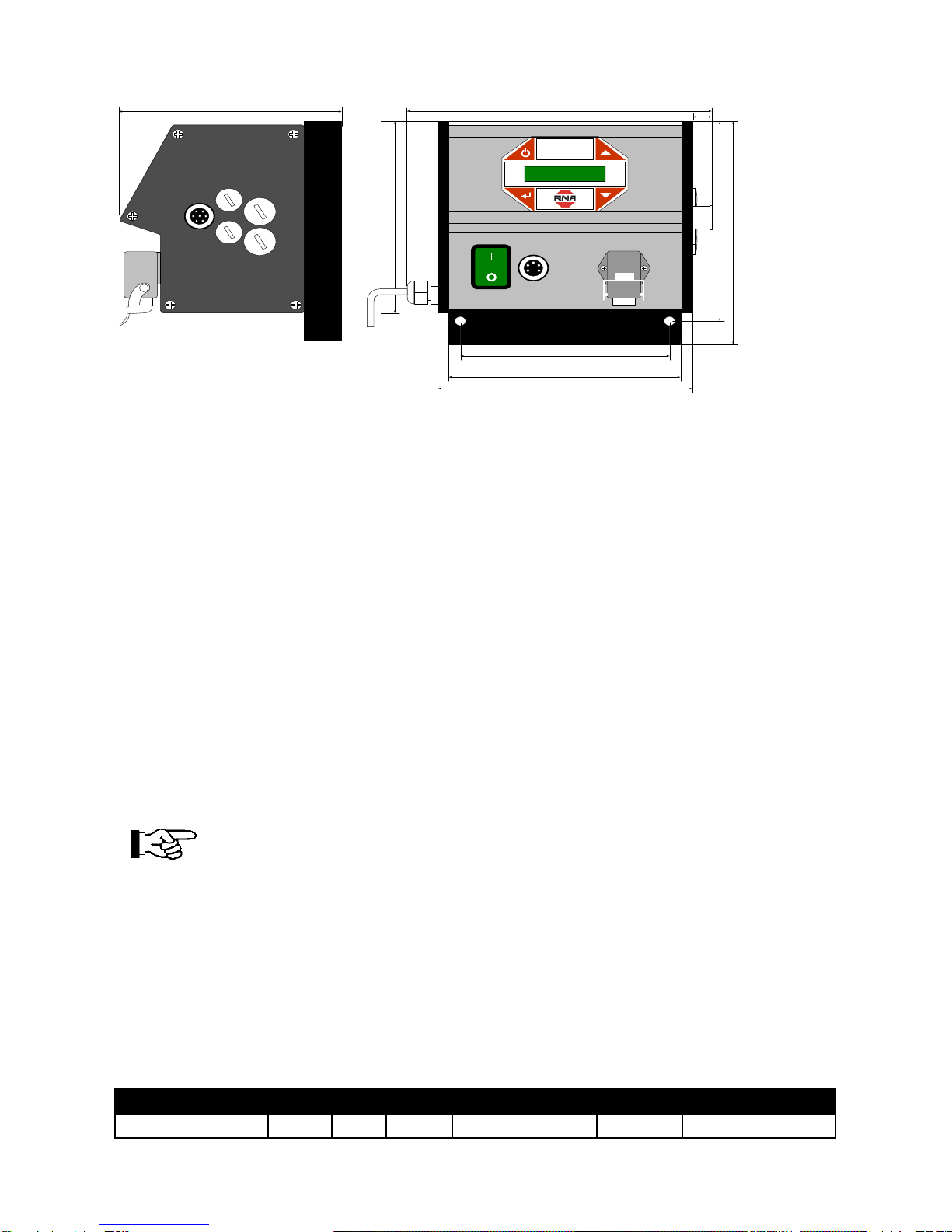
1.3 Standard Features
Dynamic electronic protection designed for output short circuits and output overloads.
Active protection of the magnets and feeder.
Permanently regulated speed that ensures stable operating behaviour as well as a recursive speed
adjustment.
The feeder requires less maintenance.
Since the frequency is automatically adjusted to the changes in the conveying properties, this
reduces the necessity of frequent fine adjustments on the feeder’s springs.
Less electricity consumption (around 50%).
Less electricity is needed to operate the feeder when it runs in the resonant range.
Flexible choice of frequency of resonance (25-150 Hz).
The conveyor resonance can be finely tuned to an optimal frequency for a certain application without
taking into account the mains frequency.
Independent when there are mains fluctuations (volts / freq.).
Control over the entire feeding system.
Two sensor amplifiers.
oTwo independent 24V DC remote control inputs to control the feeding installation
(accumulation monitoring).
Speed control through analog input.
Communication features (additional connection required).
o24V electrically isolated input for the Start/Stop control.
o“Ready for Operation” message (optocoupler, 24VDC, 20mA).
oActive message (optocoupler, 24VDC, 20mA).
oActive message via relay contact. 250 V AC 1 Amp.
Mains connection performance after mains connection.
Firmware upgrade over USB connection.
1.4 Optional Features (in preparation)
Immediate Stop function by using the active brake control. This option stops the feeder immediately
when a Stop order is given, i.e. contrary to the resonance dying away on its own, it prevents the
vibratory drive from “coasting”.
This option is especially useful when applying counters, i.e. when an exact number of parts has to be
counted without that surplus or undesired parts fall from the feeder after the correct number of
pieces has been counted.
Multiple calibration. Here, the control system can be used with a series of up to eight different feeders
without having to readjust every time.
As an option, there is a 24V electrically isolated control input for the change between different speed
levels.
Alarm signals (voltage-free contact).
Fieldbus (additional module required).
PROFIBUS DPV1.

Rhein-Nadel Automation 5 14.04.2014
VT-BA-ESR2500/2800-GB
2 General
2.1 Overview Operating Instructions
The ESR2500 / 2800 control system was developed for a high vibratory performance for all RNA feeders. To
handle the control system correctly, please read through this manual carefully. Incorrect handling of the
vibratory control can lead to trouble in the control system, reduce its life or cause other errors.
These operating instructions will help you with the installation, programming and troubleshooting your
vibratory control.
Chapter 1, Introduction, describes the functions and features of the vibratory control.
Chapter 2, How to Read these Operating Instructions, introduces this manual and informs you about the
approvals, symbols and abbreviations used in it.
Chapter 3, Safety Regulations and General Warnings, contains instructions about how to operate the
vibratory control correctly.
Chapter 4, Installation, describes the mechanical and electrical installations.
Chapter 5, Operation, shows how the vibratory control is operated and programmed over the control panel.
Chapter 6, General, contains technical data about the vibratory control.
Chapter 7, Alarms, helps when solving problems that may arise whilst using the vibratory control.
Available documentation for the vibratory control type ESR 2500 / 2800
The operating instructions for ESR2500 / 2800 provide the necessary information to put the drive into
operation.
(Option in preparation)
The Profibus operating instructions for the type ESR2500 / 2800 provide the necessary information for
the control system, monitoring and programming of the vibratory control over the Profibus fieldbus.
2.2 Applied Standards
EC Conformity
The control unit complies with the following regulations:
EC EMC Directive 2014/30/EU;
EC Low Voltage Guideline
2014/35/EU
Applied harmonised standards:
DIN EN 60204, T.1
EN 61439-1

Rhein-Nadel Automation 6 14.04.2014
VT-BA-ESR2500/2800-GB
2.3 Symbols
The symbols used in these operating instructions:
Caution!
This warning triangle indicates safety regulations.
Failure to observe this warning can lead to serious injuries or death!
This hand shows the reader (operator) what he must be aware of.
*
This symbolises a standard adjustment.
2.4 Abbreviations
Alternating current
AC
Ampere/AMP
A
Direct current
DC
Electromagnetic compatibility
EMC
Hertz
Hz
Local control panel
LCP
Millisecond
ms
PLL circuit
PLL
Printed circuit board
PCB
Second
s
Volt
V
Watt
W

Rhein-Nadel Automation 7 14.04.2014
VT-BA-ESR2500/2800-GB
3 Safety Regulations and General Warnings
It is absolutely necessary to read and to understand the safety regulations. This ensures that valuable
material is not damaged and prevents injuries.
It must be guaranteed that all persons working with this control unit know and observe the safety regulations.
The control unit described in this manual is for operating the RNA sorting and linear feeders.
The limiting values indicated in the technical data must be observed.
Work on the electrical equipment / machines / installation may only be carried out by a
specialised electrician or by a person instructed in electrotechnology under the direction and
supervision of a qualified electrician in accordance with the regulations of electrical
engineering.
All safety and warning signals on the machine/installation must be observed!
The electrical devices of a machine/installation have to be checked and controlled regularly.
Defects like loose connections or damaged cables must be eliminated immediately!
Before starting operation, please make sure that the safety earthing is intact and installed at
the point of connection. Only testing instruments approved for this purpose are allowed to
be used to test the safety earthing connection.
Caution!
The DC connection capacitors of the vibratory control remain loaded after switching off the
power. To prevent the risk of an electric shock, switch the control system off from the mains
before maintenance work and wait at least as long as indicated below.
ESR 2500
10 minutes
ESR 2800
15 minutes
3.1 Instructions for Putting into Operation
The connecting cable between the control unit and the vibratory bowl feeder must be
shielded, and the sheath must be connected on both ends to the safety earthing line.
The maximum permissible cable length is 3 m.
Before the control unit is connected to the mains and switched on, it is absolutely necessary
to check the following points:
• Is the control unit in a good, safe operational condition and closed with all screws?
• Are the connection locks blocked/screwed down?
• Are all the cables and screw fittings intact?
• Is the INTENDED USE guaranteed?
• Does the indicated mains voltage on the control unit tally with the local mains voltage?
The control unit may only be put into operation when all the questions asked above can definitely be
answered with YES.
Before starting with the operation after maintenance works or after changing the control
units/vibratory control, set the power output to minimum before switching on. Check whether
the system functions correctly when you raise the power output.

Rhein-Nadel Automation 8 14.04.2014
VT-BA-ESR2500/2800-GB
Before opening the control unit, pull the mains plug and wait for as long as indicated below,
so that the capacitor load can phase out.
Discharging time:
ESR 2500
10 minutes
ESR 2800
15 minutes
3.2 Operating Mode
To prevent any mechanical and / or electrical damage on the ESR 2500 / 2800 control system or connected
units, the parameters listed under point 4.2 must be strictly observed. If you do not find your certain type of
drive unit listed in the table, please contact “Rhein Nadel Automation”. We will be glad to assist you.
To make sure that the drive unit runs in a quiet and stable manner, it is important to use a
well-tuned drive. Please refer to the manuals on drive units to find out how the springs have
to be adjusted.

Rhein-Nadel Automation 9 14.04.2014
VT-BA-ESR2500/2800-GB
4. Installation
This chapter deals with the mechanical and electrical installation of the power and control connections.
4.1 Course of Putting into Operation
The vibratory control is designed to enable quick and unproblematic installation by following the steps
described below:
Read the safety regulations before installing the unit.
Mechanical installation
Mechanical assembly
Electrical installation
Connection to the mains and protective earthing,
Vibratory connections and cables,
Cable for the control connection.
Adjustment
Calibration
Programming
4.2 Preinstallation
Planning the place of installation
Before starting with the installation, it is important to plan the installation
of the control system and vibratory bowl feeder. If this is not done, it
could lead to more work during and after installation.
Choose the best possible position by taking the following into account:
Ambient temperature
Method of installation
How the unit is to be controlled
Position of the control system
Cable layout
4.3 Mechanical Installation
Mechanical dimensions

Rhein-Nadel Automation 10 14.04.2014
VT-BA-ESR2500/2800-GB
Mechanical installation
The ESR2500 / 2800 control system is mounted with two M8x40mm screws through two holes in the heat
sink under the casing.
The unit can be mounted either directly onto the base plate of the feeder or onto the base frame of other
machines.
By mounting the control system directly onto the feeder, it is exposed to strong vibrations which can shorten
its life. It is, therefore, strongly recommendable to mount the control system onto a non-vibrating,
mechanically stable structure like e.g. onto the base frame of a machine.
4.4 Electrical Installation
Fuses
The unit is protected internally by a 4A 5x20mm time-lag fuse in the mains supply line.
The mains connection has to be protected over an overload protection with a C 16A fuse.
Earthing and Mains
Check whether the mains voltage is identical with the information on the rating plate of the
unit.
The ESR2500 / 2800 controls are units of class protection 1 that have to be earthed according to the
regulations.
Connecting the vibratory bowl feeder
To achieve an optimum performance, the maximum load current of the vibratory bowl feeder has to be set
according to Table 1 “Connection table for max. current setting S301”.
Information about the maximum current for the feeders can be found on the rating plate on the vibratory bowl
feeder drive.
Current setting
2500
2800
S301-1
S301-2
S301-3
S301-4
S301-5
100%
5.53 A*
9.00 A*
X01-1(L)
S301-3
S301-2
NC
X01-2(N)
166,00
173,00
156,00
173,00
190,00
193,00
14,00
227,50
166,00

Rhein-Nadel Automation 11 14.04.2014
VT-BA-ESR2500/2800-GB
50%
2.75 A
4.50 A
X01-1(L)
NC
S301-4
S301-3
X01-2(N)
33%
1.83 A
3.00 A
S301-3
X01-1(L)
S301-1
NC
X01-2(N)
25%
1.37 A
2.25 A
NC
X01-1(L)
S301-4
S301-3
X01-2(N)
Table 1 –Connection table for max. current setting S301
01 02 03 04
Load
L N
X01S301
123 4 5
100% Current setting
01 02 03 04
Load
L N
X01S301
123 4 5
50% Current setting
01 02 03 04
Load
L N
X01S301
123 4 5
33% Current setting
01 02 03 04
Load
L N
X01S301
123 4 5
25% Current setting
Bowl feeder’s
drive system
Max.
Current[Aeff]
Max. Magnetic
gap(mm)
Frequency range
Magnet colour
SRC - N 160 - 2
0.6
0.5
90…120 Hz
Black
SRC - N 200 - 2
1.2
0.5
90…120 Hz
Black
SRC - B 200 - 2
1.2
0.5
90…120 Hz
Black
SRC - N 250 - 2
2.6
1.2
90…120 Hz
Black
SRC - B 250 - 2
2.8
1.2
90…120 Hz
Black
SRC - N 400 - 1
3.8
2.8
45…60 Hz
Red
SRC - N 400 - 2
4.3
1.2
90…120 Hz
Black
SRHL - 400 - 1
5.7
2.8
45…60 Hz
Red
SRHL - 400 - 2
5.3
1.5
90…120 Hz
Black
SRC - N 630 - 1
5
2.8
45…60 Hz
Red
SRC - N 800 - 1
8,5
2.8
45…60 Hz
Red
Table 2 –RNA bowl drives

Rhein-Nadel Automation 12 14.04.2014
VT-BA-ESR2500/2800-GB
Linear feeder’s
drive system
Max. Current
[Aeff]
Max. Magnetic
gap(mm)
Frequency range
Magnet colour
SLL 175
0.07
0.8
90…120 Hz
Black
SLL 400
0.6
1
90…120 Hz
Black
SLL 800
1.4
3
45…60 Hz
Red
SLL 804 < 1600
1.4
3
45…60 Hz
Red
SLL 804 ≥ 1600
2.8
3
45…60 Hz
Red
SLF 1000
2.8
2.5
45…60 Hz
Red
SLF 1500
5,6
2,5
45…60 Hz
Red
GL 01
0.6
1.0
90…120 Hz
Black
GL 1
1.1
1.2
90…120 Hz
Black
SLK N6
1.4
2.5
45…60 Hz
Red
SLK N6 G
1.4
2.5
45…60 Hz
Red
Table 3 –RNA linear feeders
4.5 Control connections
Sensor inputs and sensor connections
The control unit has two sensor inputs that can be used for checking the conveyor media (accumulation
monitoring) and other monitoring functions. Two sensors of the types NPN and PNP can be connected. Fig.
1 “Passive Optical Sensor” shows how an optical sensor is connected to Sensor Input 1, and Fig. 2
“Proximity Switch” shows how a proximity switch is connected to Sensor Input 1. Two sensors can be
connected by means of a cable distributor, as is shown in Fig. 3.
01 02 03 04
X02
+24V
E2 E1+24V 0
05
B1
Sensor 1 input
Sensor 2 input
24VDC, max 120mA
Reference
24VDC with 1.8 Kohm pullup
Fig. 1 Passive Optical Sensor

Rhein-Nadel Automation 13 14.04.2014
VT-BA-ESR2500/2800-GB
01 02 03 04
X02
+24V
E2 E1+24V 0
05
B1
1 3
4
Sensor 1 input
Sensor 2 input
24VDC, max 120mA
24VDC with 1.8 Kohm pullup
Reference
+-
A
XS 3.2 /
XS 3 /
XS 3.1 /
Anschluß eines Sensors und eines Kontaktes mit Adapter.
Gehäuse
Y - Kabel als Verteiler
Fig 2 Proximity Switch / Active Optical Sensor
Connection diagram
ESR 2500 / ESR 2800
Fuse F1
4A TR
01 02 03 04
Load
L N
01 02 03 04 05
X02
X01
S403
max. 30V / 100mA
Q01
LN PE
LN
S304
+24V
E2 E1+24V 0
Queue control
123 4 5 6
+24V
0V
Active Ready
7 1 2 3 4
Option
X03
+24V
0V
Release
Slow /
Fast
Queue
output
5 6 7
+10V
0V
Speed 0-10V
10kOhm
S100
Active
Relay out
230V/6A
USB Fieldbus
Option Option
123 4 5
S301
Max current
setting
housing
Connection of a sensor and a contact with adapter
Y-cable as junction

Rhein-Nadel Automation 14 14.04.2014
VT-BA-ESR2500/2800-GB
5 The Display of the Control Unit (keypad)
5.1 Control Panel –Display
The control panel of the ESR2500/2800 control unit consists of 4 keys and a display with 2x16 characters.
Speed 100 % A
Stopped
The keys have the following functions:
ON / OFF
During calibration, this key is also used as the Escape key to end
calibration.
Enter:
This is used to activate menus or parameter settings as well as to finally
acknowledge these settings.
When a parameter has been activated for setting, the parameter value is
marked in brackets, as is shown here:
“< XXXX >”
Arrow keys:
These keys are used to navigate through the menus.
If a parameter is activated, they are used to set this parameter.

Rhein-Nadel Automation 15 14.04.2014
VT-BA-ESR2500/2800-GB
5.2 Navigating Through the Menus
Operation of the ESR2500/2800 control system is divided into 1 main and 2 submenus. From the main
menu, one has access to the setting or calibration menu by entering the appropriate password for this menu.
The arrow keys are used to navigate up or down through the particular menus. The
menus are circular, so that navigating past the last page of a menu will take you back to
the first page again and vice-versa.
To change the parameter of a certain option, first navigate to the desired option, as
described above. To activate the submenu of this option, press the Enter key.
In the submenu, you can either adjust the parameter directly or reach a lower level of
the submenu by applying the same procedure as described above.
Once you have reached the parameter you would like to set or change, activate this
parameter with the Enter key.
As soon as the parameter has been activated and can be reset, it will appear in brackets.
Speed <100>% A
Stopped
When navigating through the menus, the parameters are displayed without brackets.
When a parameter is active, the arrow keys change their function, i.e. they no longer serve to navigate
through the menus but to set the active parameter.
Once you have finished with the parameter setting, press Enter to acknowledge the new
setting and the parameter setting will be stored.

Rhein-Nadel Automation 16 14.04.2014
VT-BA-ESR2500/2800-GB
5.3 The Menu System
5.4 Main Menu
The Main menu consists of Status, Information and Performance settings.
The Status page displays the speed and the present status of the control system.
The speed can be set from 0-100% in the Manual operating mode as well as from minimum speed –which is
calculated by the control system –to 100% in the Auto operating mode.
Speed 100 % A
Stopped
The speed setting determines the vibration amplitude.
The operating mode is displayed to the right of the speed percentage, i.e. with an M if the control system is in
Manual operating mode and with an A if it is in Automatic operating mode.
In Manual operating mode, the speed is displayed in percent of the maximum output voltage. If the control
system is calibrated and the operating mode is switched to Automatic, then the speed will be displayed as a
percentage of the maximum calibrated vibration (speed).
The second line shows the present status of the control system.
Speed 100 % A
Stopped
Stopped: The feeder has been stopped with the ON / OFF key.
Ready: The feeder is stopped through an external source like e.g. an accumulation sensor,
the external release input or a fieldbus command.
Operation: The feeder is in operation.
Fault: There is a fault.
After the Status text, the display shows the status of the external signals starting with “*” and followed by a
“1” if Accumulation Sensor 1 is active, by a “2” if Accumulation Sensor 2 is active and by an “R” if Release
Input has been set as active, i.e. the feeder is not released.
Speed 100 % A
Ready *12R >AN
OPTION
If the feeding speed is controlled by an external source, the active control type is displayed with an >
followed by a two-character code.
The character codes are:
“HS” Speed is set to high speed.
“LS” Speed is set to low speed.
“AN” Speed is controlled by the analog input.
“FB” Fieldbus controls the control system.
Speed 100 % A
Ready >FB
The Info page shows the measured values for voltage, current, mains current and frequency.
The page “Current Settings” has to be configured according to the wired current setting in the Calibration
menu!
The page “Extended” enables access by means of a password to settings and calibration. The preset
password for the Settings menu is 1000 and for the Calibration menu 2000.

Rhein-Nadel Automation 17 14.04.2014
VT-BA-ESR2500/2800-GB
Settings menu
Some of the features in the “Settings Menu” are optional (in preparation) and have to be activated by
entering an activation code. Accordingly, access to related submenus remains blocked until the
corresponding activation code has been entered. If a menu is blocked, a little padlock will be shown in the
bottom right-hand corner of the display.
Analog
Speed Input
Thus, the menu system only refers to the menu features that are activated. In addition, this makes navigating
through the menus very simple, because there is only a minimum of menus one has to navigate through.
The activation codes are unique for every single control system and can be purchased by indicating the
desired option together with the series number of the unit. With some of the options, additional cables or
additional hardware will have to be installed in the unit.
After activating an optional feature by entering the corresponding activation code, the whole submenu tree
opens up and you will have access to the parameter settings in connection with this feature.
As a special parameter via digital inputs or outputs, you can choose whether the function is to be configured
as active high (24V) or active low (0V).
Multiple calibration: (OPTION in preparation)
The ESR2500 / 2800 controls are prepared for the “Multiple Calibration” option.
Once this option has been activated with the corresponding activation code, up to eight single calibrations
and settings can be stored. This means that you can operate up to eight different vibratory bowl feeders,
alternatively up to eight different settings, with just one control unit (alternating bowls).
All the feeder-related calibration values and setting parameters like sensor type and functionality, ramps, etc.
are specifically filed for each of the sorting installations.
Only common parameters like display settings and selected language, etc. are generally valid for all
calibrations.
In the detailed parameter description further below, the parameters are marked as “Setting-specific” or
“General”.
Accumulation monitoring control:
The feeder can be controlled with up to two 24V signals at “Sensor connection” X3. Refer to connection
diagram on page 13. The signal can, for instance, come from a photocell that monitors whether an output
track is full or not. The submenus of the accumulation monitoring control supply possibilities to configure
accumulation signals.
Each input can be set as “blocked”, “active at 24V” or “active at 0V”. If the input has been set to “blocked”,
the control system ignores this signal. If the input has been set to “active at 24V” or “active at 0V”, an active
accumulation signal forces the control system into “Ready Status” and stops the feeder. As soon as the
signal becomes inactive, the control system switches over to “Active Status” and the feeder starts to run
again.
A start and stop delay can be configured for every sensor input. Delay is the time in ms between receiving
the sensor signal and processing it.
The sensor types NPN and PNP can be selected on the page Sensor Type.

Rhein-Nadel Automation 18 14.04.2014
VT-BA-ESR2500/2800-GB
On the Sensor Link page, you can combine two sensor inputs as “AND”, “OR” as well as “XOR”.
If set to “AND”, both signals have to be active before the control system stops the feeder. If set to “OR”, only
one of the two signals has to be active before the control system stops the feeder. If set to “XOR”, the control
system stops the feeder if both input signals oppose each other.
Parameter
description
Output
parameter
Range
Comment
Sensor Input 1
Stop / Start
inactive
active / 0V / 24V
Setting-specific
Start delay
300 ms
0 - 60000ms
Setting-specific
Stop delay
300 ms
0 - 60000ms
Setting-specific
Sensor type
NPN
NPN / PNP
Setting-specific
Sensor input 2
Stop / Start
inactive
active / 0V / 24V
Setting-specific
Start delay
300 ms
0 - 60000ms
Setting-specific
Start delay
300 ms
0 - 60000ms
Setting-specific
Sensor type
NPN
NPN / PNP
Setting-specific
Sensor
links
AND
AND / OR / XOR
Setting-specific
Ramps
Every time the control system sets the feeder going, the Start ramp (soft start) sets a time-controlled ramp for
an oscillation amplitude. At this moment, the control system changes over to Operation status. If this time
has been set too short, the vibratory bowl feeder strikes. Because of its own dynamic reaction, heavy feeders
tend to overoscillate if the vibration is built up too quickly.
Stopping the vibratory bowl feeder should not normally be delayed. A delay could, however, be necessary in
some cases to avoid the wrong orientation of parts on the feeder when it is stopped abruptly.
The time setting determines how long the oscillation build-up from 0% to 100% or its phasing out from 100%
to 0% will take. For example: if the “Start Ramp” is set to 1000 ms, the feeder will take 1 second to build up
the oscillation from 0% to 100%, and 500 ms to build up the oscillation from 0% to 50%.
Parameter description
Output parameter
Range
Comment
Start ramp
300 ms
50 -
20000ms
Setting-specific
Stop ramp
300 ms
50 -
20000ms
Setting-specific

Rhein-Nadel Automation 19 14.04.2014
VT-BA-ESR2500/2800-GB
Display setting
The display on the control system can be configured according to wish.
Contrast / brightness can be set in the menu under Display Calibration. If the light is set to “Normal”, it will be
switched on by pressing a key and it goes out again after 10 seconds. If the light is set to “On”, it will stay on
all the time, and if it is set to “Off”, it will stay off all the time.
Also the language can be selected (see table).
Communication
The submenu “Release” supplies alternatives to set the release input to “blocked”, “active” at 24V or “active”
at 0V. If the input has been set to “inactive”, the control system ignores this signal. If the input has been set
to “active” at 24V or 0V, an active release signal will release the control system and the feeder starts. As
soon as the signal becomes “inactive”, the control system switches over to “Ready Status” and the feeder
stops. A switch-on and switch-off delay of the release signal can be configured separately.
The submenu “Active Output” is used to configure the Active output signal that can be set to “Active On” or
“Active Off” when the feeder is in operation. The signal can also be delayed before it becomes inactive.
The submenu “Active Relay” supplies similar functions to the submenu “Active”, with the exception that the
output signal drives a relay.
The submenu “Ready Output” is used to configure the Ready output signal that can be set to “Active On” or
“Active Off” when the feeder is ready for operation.
Parameter
description
Output
parameter
Range
Comment
Contrast
50 %
0 - 100%
General
Brightness
100 %
0 - 100%
General
Light control
Normal
Normal / Automatic OFF / ON
General
Language
English
English / German / Danish / French
General

Rhein-Nadel Automation 20 14.04.2014
VT-BA-ESR2500/2800-GB
Parameter description
Output
parameter
Range
Comment
Release Input 2
Release On
Inactive / active
Blocked / 0V / 24V
Setting-specific
Release delay Start
300 ms
0 - 60000ms
Setting-specific
Release delay Stop
300 ms
0 - 60000ms
Setting-specific
Active Output
Active output On
active / off
Setting-specific
Active output Off delay
300 ms
0 - 60000ms
Setting-specific
Active Relay Output
In operation =
Inactive / active /
off
Setting-specific
Active output relay Off delay
300 ms
0 - 60000ms
Setting-specific
Ready Output
Ready =
Inactive / active /
off
Setting-specific
Analog speed input (option in preparation)
The speed setting (0-100%) can be controlled from an analog input that can be set to 0-10V, 0-5V or 4-
20mA.
Parameter description
Output
parameter
Range
Comment
Set 100% speed
0-10V
0-10V/0-5V / 4-20mA
Setting-
specific
High/low speed (option in preparation)
The high/low input signal can switch the control system back and forth between “high” and “low” speed. High
speed corresponds to the speed setting, whereas a low speed corresponds to the percentage of the current
speed setting.
The signal for high/low can be configured as follows: if the signal is set to Blocked, the control system will
ignore this signal. If it is set to Active at 24V or 0V, an active signal adjusts the control system to a high
speed and an inactive signal adjusts it to low speed. Low speed is set to a percentage of the current speed
setting. An acceleration delay can be configured to accelerate a delay time received from an active input
signal to the control system to high speed. A deceleration delay can also be set. This is the time between a
received inactive signal and the moment in which the feeder starts to slow down to a low speed.
Parameter description
Output
parameter
Range
Comment
High speed
Blocked
Blocked / 0V / 24V
Setting-specific
Low speed percent
25%
0-100%
Setting-specific
Acceleration delay
300 ms
0-60000ms
Setting-specific
Decelaration delay
300 ms
0-60000ms
Setting-specific
Other manuals for ESR 2500
1
This manual suits for next models
1
Table of contents
Other RNA Control Unit manuals
Popular Control Unit manuals by other brands

Anybus
Anybus CompactCom 40 Modbus-TCP Network guide

Belimo
Belimo ZoneTight Z2050Q-F installation instructions

Texas Instruments
Texas Instruments INA260 user guide

Trinamic
Trinamic PANDrive PD-109-57 Electronic manual

Telit Wireless Solutions
Telit Wireless Solutions ZE60-2.4 user guide

Zennio
Zennio ZVPCB1MB Assembly instructions