Roadragon MT-009 4G User manual

MT-009 User manual
0
User Manuel
M-T009 4G

MT-009 User manual
1
Contents
1 Introduction....................................................................................................................................................2
1.1 product description............................................................................................................................. 2
2 Product Overview.......................................................................................................................................... 2
2.1 Parts List............................................................................................................................................. 2
2.2 Interface Definition.............................................................................................................................2
2.2.1 Host interface...........................................................................................................................2
2.2.2 Matters needing attention in equipment wiring...................................................................... 3
2.3.1 Parameters details....................................................................................................................4
2.3.2 Characteristic parameter..........................................................................................................4
2.4 Function.............................................................................................................................................. 5
2.4.1 Functions Explaination.........................................................................................................5
3 Getting Started............................................................................................................................................... 7
3.1 Installation.......................................................................................................................................... 7
3.1.1 Installing a SIM Card.............................................................................................................. 7
3.1.2 Device installation Precautions............................................................................................... 7
3.1.3 Attention to Equipment Wiring...............................................................................................7
3.2 Precautions..........................................................................................................................................8
3.2.1 Meaning of the indicator......................................................................................................... 8
3.2.2 installation instructions............................................................................................................8
3.2.3 Analysis and elimination of common problems......................................................................9
3.3 Scenario...............................................................................................................................................9
4 Short message instructions.............................................................................................................................9
4.1 basic operation settings.....................................................................................................................10
4.2. anti-theft alarm location query settings...........................................................................................10
4.2.1 location query........................................................................................................................ 10
4.3. Garrison fortification.......................................................................................................................10
4.4. Vibration alarm:............................................................................................................................10
4.5 shift alarm:........................................................................................................................................11
4.6 Open oil cut off.................................................................................................................................11
4.7 Device recovery query settings........................................................................................................ 11

MT-009 User manual
2
1 Introduction
1.1 product description
MT-009Z is a 4G full Netcom vehicle positioning terminal carefully built for the Internet of Vehicles. It
integrates 4G full Netcom wireless communication technology and GPS/BDS satellite navigation and
positioning technology. 3-axis sensor, intelligent power-saving wake-up work. It has functions such as DC
detection, ACC detection, power failure alarm, overspeed alarm, mileage statistics, and remote fuel and
power cutoff. With the global positioning service platform, the real-time acquisition, tracking and
positioning functions of vehicle data are realized.
2 Product Overview
2.1 Parts List
Item
Photo
Main product
3MM sticker
Hidden install OBD
cable (Optional)
2.2 Interface Definition
2.2.1 Host interface

MT-009 User manual
3
Property
color
description
1
Yellow
Oil road negative
2
Orange
ACC
3
Black
battery negative
4
Red
battery positive
1. Relay white wire connected to battery positive
2. Relay yellow wire is connected to the position yellow line
3. The two green wires of the relay are respectively connected to the oil pump line (the oil pum
p line needs to be disconnected). The direct red line without the relay is connected to the positiv
e pole of the battery, and the negative line of the black line can be used.
2.2.2 Matters needing attention in equipment wiring
a. power supply, ACC, oil and electricity control line (4Pin)

MT-009 User manual
4
b. the equipment standard power supply for 12V-100VDC power line, please use the original offer,
the red line for the positive power supply, black for the cathode of the power supply; please ch
oose the cathode of the power supply grounding alone or ground installation, not with other groun
d together;
c. equipment orange line to the ACC line, be sure to pick the ACC vehicle terminal will switch,
according to the ACC state to determine whether to enter the fortification; if no ACC line will al
low vehicles to enter the default fortification state, vehicle vibration occurs, will trigger a vibratio
n alarm. If the anti-theft function is not needed, the ACC line can be directly connected with the
positive pole of the power supply.
d. break the oil and electricity control line (yellow line) to connect the yellow line on the relay.
2.3 Parameters
2.3.1 Parameters details
Property
description
Product size
83mm * 33mm * 13.5mm
Shell material
plastic
Product renderings
2.3.2 Characteristic parameter
function name
Yes
No
function name
Electrical C
haracteristic
s
Power supply
●
Power supply
Operating voltage range
●
Operating voltage range
Working current
●
Working current
sleep current
●
sleep current
Built-in battery capacity
●
Built-in battery capacity
Environmen
tal characte
ristics
range of working temper
ature
●
range of working temperature
Storage temperature rang
e
●
Storage temperature range
Operating humidity rang
e
●
Operating humidity range
Communication module
brand/chip model
●
SIMCOM XM808

MT-009 User manual
5
2.4 Function
2.4.1 Functions Explaination
Communica
tion
Communication frequenc
y band
●
LTE/4
G
Supp
orted
freq
uenc
y ba
nds
LTE-FDD:B1/B3/B5/B8
LTE-TDD:B38/B39/B40/B41
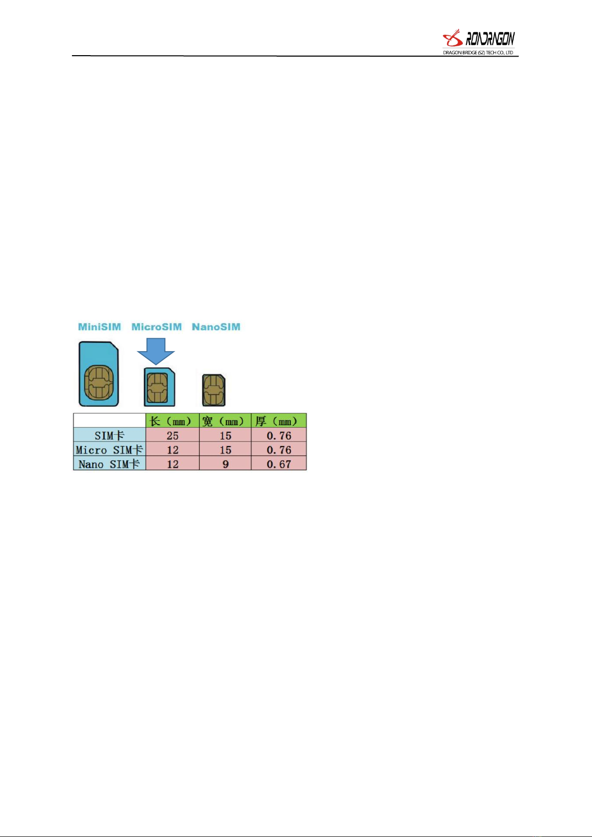
SIM card
●
Micro SIM card
communication antenna
●
Built-in antenna
Antenna Specifications
●
FPC Antenna
GPS/BD po
sitioning fe
atures
Positioning module bran
d/chip model
●
SIMCOM MX808
Targeting
●
Beidou+GPS
cold start time
●
Average 32 seconds
warm start time
●
average 1 second
tracking sensitivity
●
-162dBm
positioning antenna
●
Built-in ceramic dielectric antenna
Antenna Specifications
●
25mm*25mm*4mm
GPS band
●
L1: 1575.42±1.023MHz
Beidou frequency band
●
B1: 1561.098±2.046MHz
Number of satellite chan
nels
●
64
positioning accuracy
●
<10m (1σ)
Timing accuracy
●
<30ns (1σ)
Speed accuracy
●
<0.1m/s (1σ)
maximum acceleration
●
4g
Maximum speed
●
515m/s
maximum height
●
18000m
External int
erface
cut off oil and electricit
y
●
One external relay can be connected
ACC detection input
●
ACC detection port all the way
Dimensions
Host size (length, width
and height)
●
83mm*33mm*13.5mm
shell material
●
ABS plastic
IP protection class
●
Host weight
●
35 gram
function
Function breakdown
description
Location data report
Location tracking
The positioning information such as latit
ude and longitude is returned according
to the set interval time.
Vehicle status detectio
n
Ignition/extinguish state
The ACC switch status is included in e
ach uploaded packet.
Vehicle power failure remind
er
Turn on the backup battery. When the
host detects that the vehicle voltage is l
ess than 5V, it will report the power fa
ilure reminder.

MT-009 User manual
6
Support power failure alarm, overspeed alarm and other multiple alarm functions;
It can be connected to an external oil-cutting relay/wireless oil-cutting accessory, which sup
ports the function of cutting off the oil circuit/circuit of the monitored object, and realizes fu
nctions such as oil-cutting and power-cutting;
Support the function of electronic fence, users can delineate virtual electronic fence through
the platform/APP, when the device enters or exits the fence, it can be recognized by the pl
atform and an alarm will be issued;
When an alarm occurs, an alarm text message/phone can be sent to the monitoring numbe
r, and the alarm can be uploaded to the platform at the same time;
The terminal adopts industrial-grade high-stability GPRS module from well-known manufact
urers, built-in 4G high-sensitivity antenna, supports TCP/IP data transmission, and supports do
main name/IP address connection to the server;
Built-in large-capacity storage chip, which supports data storage in offline state and supple
mentary transmission of blind spot data; when the vehicle is in a place with weak wireless si
Low pressure alarm
When the host detects the vehicle volta
ge 5-10V, it reports a low-voltage alar
m reminder.
Over Speed alarm
The platform sets the maximum speed l
imit value. When the GPS speed is gre
ater than the set value, the over-speed a
larm is reported.
Oil line detection
Support platform and SMS to cut off oi
l and gas, oil and gas function
Illegal removal of the alarm
When the terminal generates a power fa
ilure alarm or triggers the light status, i
f both conditions are generated within 2
minutes, the illegal removal alarm is r
eported.
3D Collision alarm
When the collision threshold alarm occu
rs, the x axis, y axis, z axis acceleratio
n data of the acceleration sensor can be
sent to the customer platform, as well
as the speed of ten seconds before and
after the collision, and other informatio
n.
Other Functions
Blind zone re-transmission fu
nction
The terminal is located and not online,
and the data is stored up to 300. Uploa
d when the signal is online normally
EPO assisted positioning func
tion
The terminal supports the EPO assisted
positioning function to enhance the posi
tioning effect.
Inflection point
When the device orientation angle chan
ges more than a certain angle, immediat
ely upload a position data to optimize t
he trajectory.
Remote upgrade
Upgrade the housekeeper remote upgrad
e.
Low power consumpti
on
Sleep mode
G-sensor senses the vibration state of th
e vehicle in real time, and the power is
in the sport mode. When the host has
no vibration for 5 minutes, it enters th
e static mode, and the GPS module is t
urned off, and the vibration enters the s
port mode.
MT-009 User manual
7
gnal or serious interference, the vehicle will temporarily store the data of vehicle operation in
FLASH, and when the wireless signal returns to normal After that, these data can be supple
mented, so that the data is not missing. ;
Built-in 3-axis acceleration sensor, integrated with precise acceleration algorithm, real-time a
cquisition of vehicle status and other vehicle conditions;
High-sensitivity GPS/BDS dual-satellite positioning module, anti-jamming ceramic antenna, t
o achieve more stable satellite search signal, support AGPS fast positioning tracking, synchron
ous timing;
In sleep mode, it supports low battery voltage monitoring alarm, abnormal vibration alarm
and other vehicle startup, flameout, and sleep automatic reporting messages;
Support online remote upgrade and remote configuration of product parameters.
Low-power energy-saving mode, which can accurately judge the ignition and flameout statu
s of the car, and the intelligent sleep and wake-up mechanism can reduce the average power
consumption of the entire system;
3 Getting Started
3.1 Installation
3.1.1 Installing a SIM Card
3.1.2 Device installation Precautions
a. Please pay attention to waterproof products.
b. Please keep the car battery fully charged.
c. The power supply of the device is between 9V and 36V DC. The installation should first determine
whether the user's power system is within this range. Exceeding the maximum voltage of the terminal will
damage the terminal.
d. When the ambient temperature exceeds the normal operating temperature range of the terminal, it is
Recommended to power off.
e. When the vehicle is in an underground parking lot, tunnel or garage, it will affect the positioning signal.
And the communication network signal blind zone may cause the device to be unable to monitor; when the
vehicle drives out of the above area, the device will automatically resume normal operation.
f. In case of abnormal situation, please do not repair it yourself. The manufacturer is not liable for damage
caused by connecting non-original accessories or unplugging the connections between the various
components.
3.1.3 Attention to Equipment Wiring
Power supply, ACC、power supply line (4 Pin)
1. If the standard power supply of this equipment is 12 V-100VDC, please choose the power line provided
by the original factory, the red line is the positive pole of the power supply, and the black one is the

MT-009 User manual
8
negative pole of the power supply; when installing, please choose separate grounding or lap iron, do not
connect with other ground wires;
2. The orange line of the equipment is the ACC line, be sure to connect the ACC switch of the vehicle, the
terminal will judge whether to enter the fortification according to the ACC state; if the ACC line is not
connected, the vehicle will enter the default fortification state, the vibration will occur in the operation of
the vehicle, and the vibration alarm will be triggered. If the anti-theft function is not required, the ACC line
can be directly connected with the power positive pole;
3. Oil cut off electronic control line (yellow line) connected to the relay on the yellow line.
3.2 Precautions
3.2.1 Meaning of the indicator
Yellow light - GSM indicator
Status of the lights
meaning
Flash 1 time within 2 seconds
GSM initialization
Always bright
GSM communication is normal
not bright
GSM sleep/shutdown
Blue light - GPS indicator
Status of the lights
meaning
Flash 1 time within 2 seconds
Searching for satellite signals
Always bright
GPS/BDS is located
not bright
GPS/BDS sleep
Working logic
After the equipment is installed, when the yellow and blue lights are always on, the equipment e
nters the normal working state.
Static flame out state: ACC is off, and the device has a data every 5 minutes.
Sports ignition status: ACC is on, and the device has a data every 10 seconds.
Power failure alarm: After the device is connected to the power supply, the device will judge that
the power supply is connected. When the device is disconnected from the power supply within 3
seconds, the device triggers a power failure alarm and uploads it to the server.
Overspeed alarm: Set the overspeed alarm threshold. When the device speed exceeds the set value,
the device will alarm and upload to the server.
3.2.2 installation instructions
The installation mode of terminal is suggested to be concealed installation. The hidden installation of
terminal equipment should be installed by the professional agency designated by the dealer, and pay
attention to the following matters:
a. in order to avoid thieves damage, equipment selection should be concealed as far as possible;
b. avoids putting together with emission sources, such as reversing radar, burglar alarm and other vehicle
mounted communication equipment;
c. can be fixed with tie tape or with double adhesive with wide sponge;

MT-009 User manual
9
d. equipment is equipped with GSM antenna and GPRS antenna, installation should ensure that the
receiving face up (air empty), and no metal shielding above, recommended installation position:
1. The front windshield below the decoration box cover;
2. Before the instrument panel (epidermal non-metallic material) around the shelter;
3. The rear windshield trim down below.
e. If there is a metal insulation layer or heating layer on the windshield of the car, it will reduce the GPS
receiving signal and cause GPS malfunction. Please change the installation position of the equipment.
3.2.3 Analysis and elimination of common problems
Fault phenomenon
Cause Analysis
Approach
The center cannot monitor
SIM card arrears stop
Contact the network operator to pay
Is the SIM card connect well
Re install SIM card
Online parameter setting error
Refer to the manual to reset the
parameters.
vehicle is in underground par
king lot, tunnel signal is wea
k
Leave the signal difference area
Light false alarm
The installed position is in
visible light
Installed in the light position
Unable to locate
The vehicle is in an
underground parking lot, tunnel
Open the above area
Terminal antenna face is not
facing up
Re-adjust the terminal placement
3.3 Scenario
4 Short message instructions
all instructions must be input in English status
Send SMS code with mobile phone to GPS vehicle communication terminal SIM card number, se
parated symbol is comma. The comma in the following short message instruction format is Englis
h input state format, the letters are not written by the instruction, and the comma is input in Eng
lish state.

MT-009 User manual
10
4.1 basic operation settings
4.1.1 center number settings
(that is, the owner number must be done, otherwise it can not do other operations):
4.1.2 settings center number
you must use the owner number to send SMS to the terminal SIM card number
SMS format: admin123456158********
The "155********" is the number of mobile phone SIM card which needs to be bound. After rec
eiving the message that the center number is set successfully, the owner can perform other short
message instructions on the terminal or check the car on the internet.
4.1.3 modify the terminal password
please remember the password, such as forget the owner's center number can be sent to restore th
e factory settings instructions
The default terminal password is: 123456
Modify the terminal password instruction: pwd123456 666888 (666888 is a new password, must b
e six digits)
Reply message: password modification successful, new password: 666888, please be careful to kee
p!
4.2. anti-theft alarm location query settings
4.2.1 location query
The center number sends instructions to the SIM card of the terminal device, and the terminal rep
lies the last Chinese position information to the central number.
Instruction format: DW or 123
Reply information: Shenzhen city of Guang-dong Province, Long-gang District, Cloth Dragon Road,
Bantian Metro (Shenzhen) 12 meters southeast
4.3. Garrison fortification
a. defense instruction format: SF reply message: SF OK
b. instruction format: CF reply message: CF OK
4.4. Vibration alarm:
When the automobile flameout tube enters the automatic fortification, the continuous vibration for
more than 3 seconds will trigger the vibration alarm.
4.4.1 open vibration SMS alarm: 125# (default)

MT-009 User manual
11
Reply SMS: OK
4.4.2 closed vibration SMS alarm: 126#
Reply SMS: OK
4.4.3 open vibration alarm: 122#
Reply SMS: OK
4.4.4 turn off the vibration phone alarm: 121# (default)
Reply SMS: OK
4.4.5 set vibration alarm duration SMS instructions, 1-15 seconds.
Instruction: vibtime123456, n reply: vibtime set OK
N (0~15), 0 cancel vibration alarm, default 3 seconds, that is, vibration lasts 3 seconds alarm
4.5 shift alarm:
4.5.1 shift alarm setting instruction: move123456 300 (default) unit: meter reply: move OK
4.5.2 closed instruction format: move0
SMS: displacement alarm: closed
4.5.3 overspeed alarm:
4.5.4 over speed SMS alarm speed limit: speed123456 080 set speed limit of 80 km / h.
4.5.5 shut down speeding SMS Notifications: speed123456 000 (default) reply: speed OK
4.5.6 speeding SMS notification: speed123456 080
reply: speed OK reply SMS: overspeed alarm: 80km / h
4.6 Open oil cut off
When the vehicle theft occurs, the monitor can send out the oil and electricity instructions initi
atively, and cut off the oil circuit of the stolen vehicle under the premise that the vehicle is in s
afe driving, so that the vehicle can not be started.
Note: to ensure the safety of vehicles, only in the GPS terminal in the effective positioning state,
and to meet the vehicle speed is less than 20KM/H under the condition when the vehicle is stati
onary or interruption oil electric operation.
When the robbery alarm is released, the oil and electricity instructions are manually sent back by
the monitoring background, and the terminal performs the oil and electricity recovery operation, a
nd the vehicle can continue to run.
SMS break oil: DY
SMS open oil: KY
4.7 Device recovery query settings
a. restore factory settings instruction format: format

MT-009 User manual
12
Reply SMS: alarm will immediately restore the factory settings, all previous settings will be cance
led.
b. restart instruction format: CQGPS
c. query device information:
Instruction format: CXZT
Reply information: version, ID, IP, port, domain name, APN
Other manuals for MT-009 4G
1
Table of contents
Other Roadragon GPS manuals

Roadragon
Roadragon BK-800 User manual

Roadragon
Roadragon LTS-100DST User manual

Roadragon
Roadragon GLL-150 User manual

Roadragon
Roadragon LTS-100D Configuration guide

Roadragon
Roadragon LTS-3YT User manual

Roadragon
Roadragon LLS-100TS Configuration guide

Roadragon
Roadragon LTS-50DS Configuration guide

Roadragon
Roadragon TK-6WT User manual

Roadragon
Roadragon G-MT008G User manual

Roadragon
Roadragon MT-009 4G User manual


