SECTION 1: HEATER S AFETY
1
SECTION 1: HEATER SAFETY
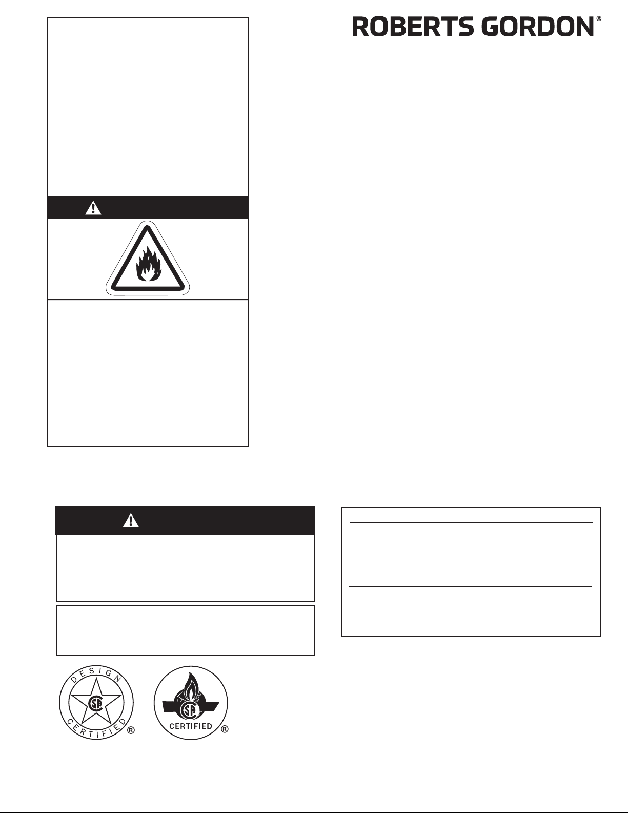
Yo ur Safety is Important to Us!
This symbol is used throughout
the manual to notify youof possi-
ble fire, electrical or burn hazards.
Please pay special attention when
reading and following the warn-
ings in these sections.
Installation, service and annual
inspection of heater must be done by a contractor
qualified in the installation and service of gas-fired
heating equipment.
Read this manual carefully before installation, opera-
tion or service of this equipment.
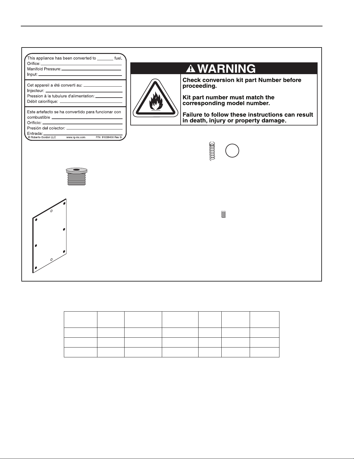
Due to the nature of gas conversions, it is important
youuse the correct conversion kit for the heater
model and gas youare converting to. Use only genu-
ine ROBERTS GORDON®conversion kits.
This heater is designed for heating residential and
nonresidential indoor spaces. Do not install in resi-
dential living and sleeping areas or basements.
These instructions, the layout drawing, local codes
and ordinances, and applicable standards that apply
to gas piping, electrical wiring, venting, etc. must be
thoroughly understood before proceeding with the
installation.
Protective gear is to be worn during installation,
operation and service. Thin sheet metal parts, includ-
ing the aluminum reflector portion of the heater and
the various venting components, have sharp edges.
To p r event injury, the use of work gloves is recom-
mended. The use of gloves will also prevent the
transfer of body oils from the hands to the surface of
the reflector.
Before installation, check that the local distribution
conditions, nature of gas and pressure, and adjust-
ment of the appliance are compatible.
This heater must be applied and operated under the
general concepts of reasonable use and installed
using best building practices.
This appliance is not intended for use by persons
(including children) with reduced physical, sensory or
mental capabilities, or lack of experience and knowl-
edge, unless they have been given supervision or
instruction concerning use of the appliance by a per-
son responsible for their safety. Children should be
supervised to ensure that they do no play with the
appliance.
For additional copies of the Installation, Operation
and Service Manual, please contact Roberts-Gordon
LLC.
1.1 Manpower Requirements
To p re vent personal injury and damage to the heater,
two persons will be required to remove the heater
from the carton. Both ends of the heater should be
lifted from the carton at the same time. The burner
should be lifted by gripping the bottom. The reflector
of the heater should be lifted using the hanger.
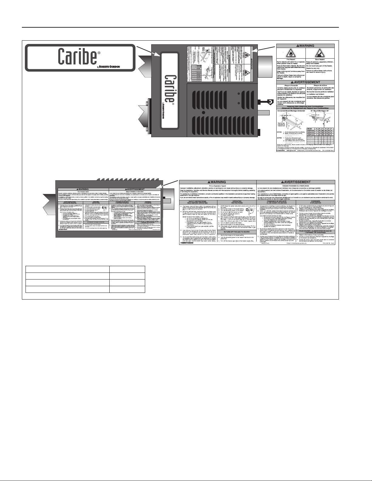
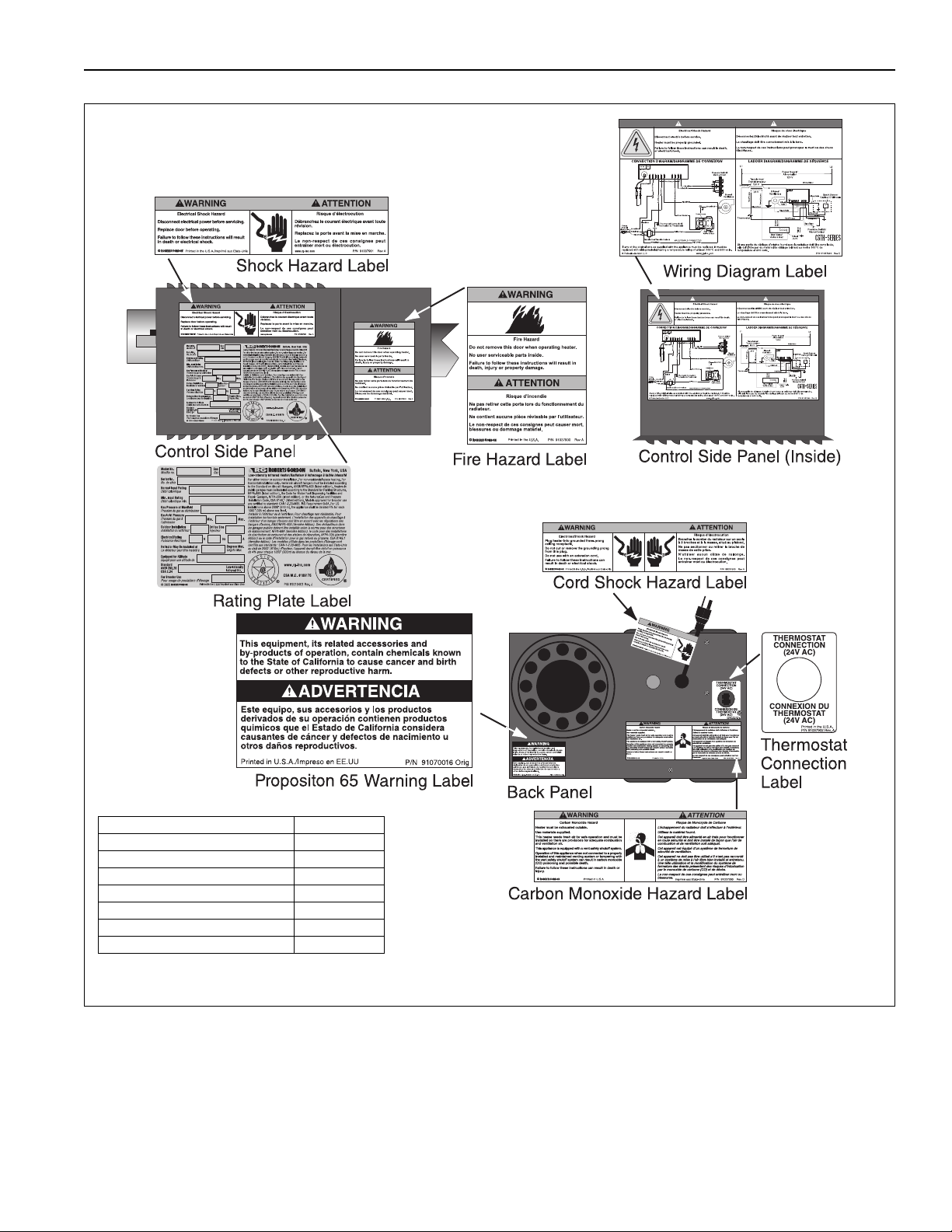
1.2 Safety Labels and Their Placement
Product safety signs or labels should be replaced by
the product user when they are no longer legible.
Please contact Roberts-Gordon LLC or your ROB-
ERTS GORDON®independent distributor to obtain
replacement signs or labels. See Page 2, Figure 1
through Page 3, Figure 2.
1.3 California Proposition 65
In accordance with California Proposition 65 require-
ments, a warning label must be placed in a highly
visible location on the outside of the equipment (i.e.,
near equipment’s serial plate). See label placement
drawing on Page 2, Figure 1 for label location. Avoid
placing label on areas with extreme heat, cold, corro-
sive chemicals or other elements. To order additional
labels, please contact Roberts-Gordon LLC or your
ROBERTS GORDON®independent distributor.