Roberts Gorden GordonRay BH Series User manual

Fuel Conversion Kit Instructions
BH-40
BH-60
BH-80
BH-100
BH-125
BH-150
BH-175
BH-200
P/N 270101NA Rev. A 11/99
Roberts-Gordon
1250 William Street
P.O. Box 44
Buffalo, New York 14240-0044
Telephone: 716.852.4400
Fax: 716.852.0854
Toll Free: 800.828.7450
http://www.rg-inc.com
Roberts-Gordon Canada Inc.
241 South Service Road West
Grimsby, Ontario L3M 1Y7 Canada
Telephone: 905.945.5403
Fax: 905.945.0511
Toll Free: 800.663.9025
© Copyright 1999 Roberts-Gordon
DO NOT store or use gasoline or other
flammable vapors and liquids in the
vicinity of this or any other appliance.
FOR YOUR SAFETY
If you smell gas:
1. Open windows.
2. DO NOT try to light any
appliance.
3. DO NOT use electrical
switches.
4. DO NOT use any telephone
in your building.
5. Leave the building.
6. Immediately call your local
gas supplier after leaving
the building. Follow the gas
supplier’s instructions.
7. If you cannot reach your gas
supplier, call the Fire
Department.
GordonRay BH
®
WARNING
Installation must be done by a contractor qualified
in the installation and service of gas-fired heating
equipment or your gas supplier.
Improper installation, adjustment, alteration, service
or maintenance will result in death, injury or property
damage. Read the installation, operation and service
manual thoroughly before installing or servicing
this equipment.
Installer
Please take the time to read and understand
these instructions prior to any installation.
Installer must give a copy of this manual to the owner.
Owner
Keep this manual in a safe place to provide your
serviceman with information should it become
necessary.


ROBERTS-GORDON
Table of Contents
BEFORE YOU BEGIN . . . . . . . . . . . . . . . . . . . . . . . . . . . . . . . . . . . . . . . .1
Read This Manual . . . . . . . . . . . . . . . . . . . . . . . . . . . . . . . . . . . . . . . . . . . . . . . . . . . .1
Questions, Comments or Suggestions . . . . . . . . . . . . . . . . . . . . . . . . . . . . . . . . . . . .1
HEATER SAFETY . . . . . . . . . . . . . . . . . . . . . . . . . . . . . . . . . . . . . . . . . . .2
Your Safety is Important to Us . . . . . . . . . . . . . . . . . . . . . . . . . . . . . . . . . . . . . . . . . .2
Important Notice . . . . . . . . . . . . . . . . . . . . . . . . . . . . . . . . . . . . . . . . . . . . . . . . . . . . .2
FUEL CONVERSION KITS . . . . . . . . . . . . . . . . . . . . . . . . . . . . . . . . . . . .3
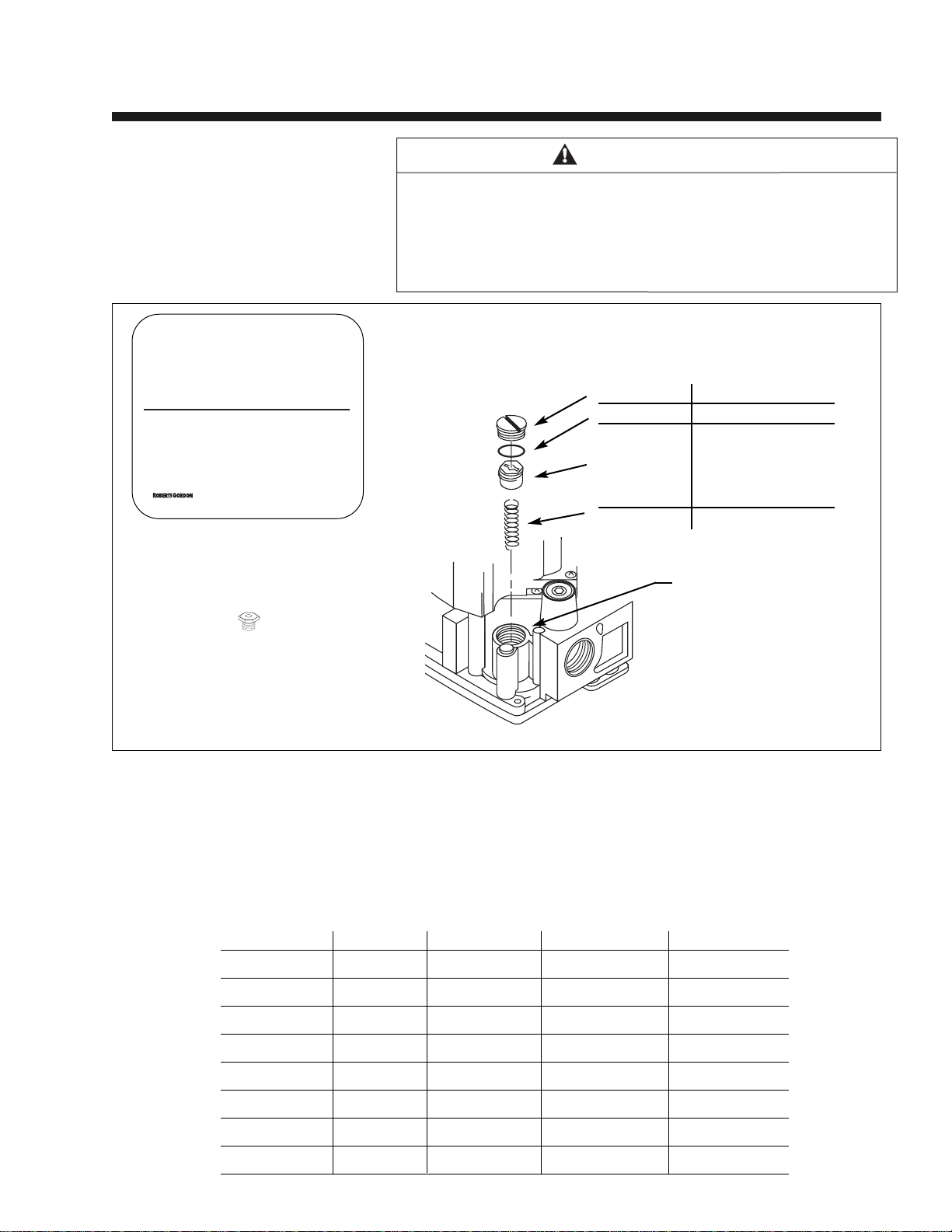
For Natural -to- Propane Conversions Only (FIGURE 1.) . . . . . . . . . . . . . . . . . . . . . .3
Contents of Fuel Conversion Kits (Natural -to- Propane) . . . . . . . . . . . . . . . . . . . . . .3
For Propane -to- Natural Conversions Only (FIGURE 2.) . . . . . . . . . . . . . . . . . . . . . .4
Contents of Fuel Conversion Kits (Propane -to- Natural) . . . . . . . . . . . . . . . . . . . . . .4
Warnings . . . . . . . . . . . . . . . . . . . . . . . . . . . . . . . . . . . . . . . . . . . . . . . . . . . . . . . . . .5
FUEL CONVERSION INSTRUCTIONS . . . . . . . . . . . . . . . . . . . . . . . . . . .6
Step 1 (FIGURE 3.) . . . . . . . . . . . . . . . . . . . . . . . . . . . . . . . . . . . . . . . . . . . . . . . . . . .6
Step 2 (FIGURE 4.) . . . . . . . . . . . . . . . . . . . . . . . . . . . . . . . . . . . . . . . . . . . . . . . . . . .7
Step 3 (FIGURE 5.) . . . . . . . . . . . . . . . . . . . . . . . . . . . . . . . . . . . . . . . . . . . . . . . . . . .8
FIGURE 6. . . . . . . . . . . . . . . . . . . . . . . . . . . . . . . . . . . . . . . . . . . . . . . . . . . . . . . . . . .9
Step 4 . . . . . . . . . . . . . . . . . . . . . . . . . . . . . . . . . . . . . . . . . . . . . . . . . . . . . . . . . . . . .9
(FIGURE 7.) . . . . . . . . . . . . . . . . . . . . . . . . . . . . . . . . . . . . . . . . . . . . . . . . . . . . . . . .10
Step 5 (FIGURE 8.) . . . . . . . . . . . . . . . . . . . . . . . . . . . . . . . . . . . . . . . . . . . . . . . . . .11
Step 6 . . . . . . . . . . . . . . . . . . . . . . . . . . . . . . . . . . . . . . . . . . . . . . . . . . . . . . . . . . . .11
CLEARANCESTO COMBUSTIBLES . . . . . . . . . . . . . . . . . . . . . . . . . . .12
FIGURES 9, 10, 11 . . . . . . . . . . . . . . . . . . . . . . . . . . . . . . . . . . . . . . . . . . . . . . . . . .13
FIGURES 12, 13, 14 . . . . . . . . . . . . . . . . . . . . . . . . . . . . . . . . . . . . . . . . . . . . . . . . .14
FIGURES 15, 16, 17 . . . . . . . . . . . . . . . . . . . . . . . . . . . . . . . . . . . . . . . . . . . . . . . . .15
OPERATION AND MAINTENANCE . . . . . . . . . . . . . . . . . . . . . . . . . . . .16
Sequence of Operation . . . . . . . . . . . . . . . . . . . . . . . . . . . . . . . . . . . . . . . . . . . . . . .16
Pre-Season Maintenance and Annual Inspection . . . . . . . . . . . . . . . . . . . . . . . . . . .16
Remember to Check . . . . . . . . . . . . . . . . . . . . . . . . . . . . . . . . . . . . . . . . . . . . . . . . .17
Remember to Check continued . . . . . . . . . . . . . . . . . . . . . . . . . . . . . . . . . . . . . . . . .18
LIMITEDWARRANTY . . . . . . . . . . . . . . . . . . . . . . . . . . . . . . . . . . . . . . .19
Printed in the U.S.A.


1
ROBERTS-GORDON
BEFORE YOU BEGIN
Read this
Manual
Read these instructions carefully before servicing this equipment.
Improper installation, servicing or maintenance will cause death,
injury or property damage. Installer must be a contractor qualified
in the installation and service of gas-fired heating equipment or
your gas supplier. After the installation is complete, check product
operation as provided in these instructions.
For additional copies of the GORDONRAY®BH Installation,
Operation and Service Manual, please contact Roberts-Gordon.
Questions,
Comments or
Suggestions
Please direct any questions, comments or suggestions to:
In the United States:
Roberts-Gordon
1250 William Street
P.O. Box 44
Buffalo, NewYork 14240-0044
USA
Telephone: 716.852.4400
Toll Free: 800.828.7450
Fax: 716.852.0854
Home Page: www.rg-inc.com
In Canada:
Roberts-Gordon Canada Inc.
241 South Service Road West
Grimsby, Ontario L3M 1Y7
Canada
Telephone: 905.945.5403
Toll Free: 800.663.9025
Fax: 905.945.0511
Home Page: www.rg-inc.com

2
GORDONRAY®BH SERIES HEATER
This symbol is used throughout the manual to notify
you of possible fire, electrical or shock hazards. Please
pay special attention when reading and following the
warnings in these sections.
Due to the nature of gas conversions, it is important
you use the correct conversion kit for the heater model
and the gas you are converting to.
Heater Safety
Your Safety
is Important
to Us
Important
Notice
In Canada:
The conversion shall be carried out in accordance with
the requirements of the provincial authorities having
jurisdiction and in accordance with the requirements of
the CAN1-B149.1 and .2 installation codes.
WARNING
Use only genuine ROBERTS GORDON conversion kits.
Failure to follow these instructions will result in
death, injury or property damage.
®
WARNING
Service and annual inspection must be done by a
contractor qualified in the installation and service of
gas-fired heating equipment.
Failure to follow these instructions will result in death,
injury or property damage.

3
ROBERTS-GORDON
Contents of Fuel Conversion Kits
(Natural -to- Propane)
Orifice
P/N (see Table below)
Gas Conversion Label:
P/N 91039400
For
Natural -to- Propane
Conversions Only
Fuel Conversion Kits Configuration
Pressure
Regulator
Housing
Cap Screw BLACK
O Ring BLACK
Pressure
Regulator
Adjusting
Screw
Spring RED
SPRING KIT: P/N 90032600
COLOR CODE FOR PROPANE GAS
WHITE
Kit Number Model BH- Orifice P/N Label Spring Kit
BH040NP 40 91910449 91039400 90032600
BH060NP 60 91910444 91039400 90032600
BH080NP 80 91910437 91039400 90032600
BH100NP 100 91910433 91039400 90032600
BH125NP 125 91910430 91039400 90032600
BH150NP 150 91910428 91039400 90032600
BH175NP 175 91910425 91039400 90032600
BH200NP 200 91910420 91039400 90032600
FIGURE 1. Conversion Kit Installation in Regulator
This appliance has been converted to _______ fuel.
Orifice: __________________________________
Manifold Pressure: __________________________
Input: ____________________________________
Cet appareil a ete converti au:
________________
Injecteur:
________________________________
Pression a la tubulure d'alimertation:
____________
Debit calorifique:
__________________________
Printed in the U.S.A./
Imprimé aux Etats-Unis
P/N 91039400
©
WARNING
Natural - to - Propane Conversion
Check Conversion Kit Part Number before proceeding. Kit Part
Number must match the corresponding model number.
Failure to follow these instructions will result in death, injury or
property damage.
All kits include this manual (P/N 270101NA) and the GORDONRAY®
BH Installation, Operation and Service Manual (P/N 170101NA).

4
GORDONRAY®BH SERIES HEATER
Kit Number Model BH- Orifice P/N Label Spring Kit
BH040PN 40 91910432 91039400 90032700
BH060PN 60 91910426 91039400 90032700
BH080PN 80 91910418 91039400 90032700
BH100PN 100 91910412 91039400 90032700
BH125PN 125 91910403 91039400 90032700
BH150PN 150 91910496 91039400 90032700
BH175PN 175 91910495 91039400 90032700
BH200PN 200 91910492 91039400 90032700
Contents of Fuel Conversion Kits
(Propane -to- Natural)
Fuel Conversion Kits Configuration
Gas Conversion Label:
P/N 91039400
For Propane -to-
Natural Conversions
Only
Orifice
P/N (see Table below)
Pressure
Regulator
Housing
Cap Screw SILVER
O Ring BLACK
Pressure
Regulator
Adjusting
Screw
Spring STAINLESS STEEL
WHITE
FIGURE 2. Conversion Kit Installation in Regulator
This appliance has been converted to _______ fuel.
Orifice: __________________________________
Manifold Pressure: __________________________
Input: ____________________________________
Cet appareil a ete converti au:
________________
Injecteur:
________________________________
Pression a la tubulure d'alimertation:
____________
Debit calorifique:
__________________________
Printed in the U.S.A./
Imprimé aux Etats-Unis
P/N 91039400
©
WARNING
Propane - to - Natural Conversion
Check Conversion Kit Part Number before proceeding. Kit Part
Number must match the corresponding model number.
Failure to follow these instructions will result in death, injury or
property damage.
All kits include this manual (P/N 270101NA) and the GORDONRAY®
BH Installation, Operation and Service Manual (P/N 170101NA).
SPRING KIT: P/N 90032700
COLOR CODE FOR NATURAL GAS

5
ROBERTS-GORDON
Warnings
WARNING
Electrical Shock Hazard
Unplug the electrical cord
from the outlet before per-
forming any service or
maintenance.
Failure to follow these
instructions will result in
death, injury or property
damage.
Explosion Hazard
Turn off the gas supply to
the heater before perform-
ing any service or mainte-
nance.
Failure to follow these
instructions will result in
death, injury or property
damage.
WARNING
Health Hazard
Gasket material may be
harmful if inhaled.
Gasket material may also
be irritating to the skin,
eyes and respiratory tract.
Failure to follow these
instructions will result in
injury.
WARNING

6
GORDONRAY®BH SERIES HEATER
NOTE: The burner may be removed to a workbench or converted in place.
a. Turn off gas supply valve, disconnect gas from burner.
b. Turn off power supply and disconnect wires from burner.
c. Unplug thermostat wires from burner.
d. If outside air is installed, disconnect.
e. Remove the (4) bolts which hold the burner on the transition
tube using a 1/2" wrench.
f. Remove the burner. Refer to
Page 6, Figure 3
.
g. Save the Gasket (P/N 02568200) or re-install a new one after
conversion.
Step 1
Fuel Conversion Instructions
WARNING
Burner is secured to transition tube by Bolts and
Lockwashers.
Upon removal of Bolts, Burner is free from Transition
Tube and will fall if not supported.
Failure to follow these instructions will result in death,
injury or property damage.
Burner (shown with tube gasket)
Gasket
Transition Tube
Bolts & Flatwashers (4)
FIGURE 3. GORDONRAY®BH Assembly Overview

7
ROBERTS-GORDON
Fuel Conversion Instructions
Remove the blower and door assembly from the burner assembly:
Unplug the blower; using a 1/4" nut driver or a phillips (+) screwdriver,
remove the (7) screws and the door assembly and set aside.
Refer to
Page 7, Figure 4.
Step 2
FIGURE 4. Burner (External View)
Install Label Here
P/N 91039400
Blower
Screws (7)
Blower Plug
Door Assembly Control Side
Door
Screws (2)

8
GORDONRAY®BH SERIES HEATER
Fuel Conversion Instructions
WARNING®
Use only genuine ROBERTS GORDON replacement parts.
Use of parts not specified by Roberts-Gordon voids warranty.
Failure to follow these instructions will result in death, injury
or property damage.
a. Remove the burner cup assembly: Unscrew the burner cup and
pull back on the flex manifold to allow the cup to clear the electrode.
Refer to
Page 8, Figure 5.
b. Remove and replace the gas orifice: Use a 1/2" open end
wrench (spanner) to remove the orifice. Apply a small amount of pipe
sealant to the threads of the replacement orifice. Be aware that
over application of sealant may cause blockage of the orifice. Insert
and tighten the replacement orifice.
CAUTION: Do not over-tighten the gas orifice.The torque value for the
gas orifice is 15in/lbs; contact your factory representative for
more details.
c. Replace the burner cup: Insure large external tooth washer is in
place, then tighten the burner cup.
d. Replace the blower and door assembly and plug in the blower.
e. Open the control side door: Using a 1/4" nut driver or a Phillips (+)
screw driver, remove the two screws and swing the door up.
Refer to
Page 7, Figure 4.
Step 3
FIGURE 5. Internal Assembly
Gas Orifice (jet)
Regulator Adjusting Screw
Regulator Outlet Plug
Electrode
Burner Cup
Assembly
Tooth Washer
Flex Manifold

Pressure
Regulator
Housing
Pressure
Regulator
Adjusting
Screw
Spring
Cap
O Ring
ROBERTS-GORDON
f. Replace the regulator spring: Using a straight slot screwdriver,
remove the cap from the regulator adjusting screw,
remove the screw and remove and replace the spring. Refer to
Page 9, Figure 6.
NOTE: Silver spring for Natural, red spring for Propane.
Refer to
Pages 3 and 4, Fuel Conversion Kits Configurations.
Replace the adjusting screw and turn down approximately 1/2".
Adjust the regulator:
a. Using a 3/16" hex key, remove the plug at the regulator outlet and
install a test tap and hose.Connect the hose to a liquid filled
manometer. Refer to
Page 10, Figure 7.
b. Turn on gas and power, turn up thermostat.
c. When unit comes on; adjust the regulator by turning the adjusting
screw to set the pressure to:
Natural: 3.5" w.c. (inches water column); Propane: 10.5" w.c.
d. Secure power and gas.
e. Remove tap and replace plug and adjusting screw.
Step 4
Fuel Conversion Instructions
FIGURE 6. Pressure Regulator
9
WARNING
Bolts must be torqued to 120 in/lbs as stated below to secure
transition tube to burner.
Transition tube will separate from burner if not torqued properly.
Failure to follow these instructions will result in death, injury
or property damage.
g. If the burner is removed, re-install the gasket and the burner on the
transition tube by inserting lockwashers and bolts, torque to 120
in/lbs.Reconnect outside air, gas and electrical supplies.For proper
installation procedures, see Venting, Gas Piping and Electrical
Sections of the GORDONRAY®BH Installation, Operation and
Service Manual (P/N 170101NA) included in this Conversion Kit.

10
GORDONRAY®BH SERIES HEATER
Fuel Conversion Instructions
Manometer
6
5
4
3
2
1
0
1
2
3
4
5
6
6
5
4
3
2
1
0
1
2
3
4
5
6
Natural Propane
10.5"
3.5"
Top View of Heater
FIGURE 7. Manometer Reading
Manometer
Reading
Electrical Shock Hazard
Disconnect electrical power before installation
or service.
Failure to follow these instructions will result
in death or electrical shock.
WARNING

11
ROBERTS-GORDON
For Model No. Enter Size for Propane
BH-40 #49
BH-60 #44
BH-80 #37
BH-100 #33
BH-125 #30
BH-150 #28
BH-175 #25
BH-200 #20
Enter following data for
Natural -to- Propane
Conversions
Enter following data for
Propane -to- Natural
Conversions
Print the requested information in the fields of the burner conversion
label as shown below.
Step 5
Fuel Conversion Instructions
FIGURE 8. Label (P/N 91039400)
From Serial Plate
Natural
3.5" w.c.
10.5" w.c.
Propane
From Serial Plate
For Model No. Enter Size for Natural
BH-40 #32
BH-60 #26
BH-80 #18
BH-100 #12
BH-125 #3
BH-150 "A"
BH-175 "E"
BH-200 6.8 mm
This appliance has been converted to _______ fuel.
Orifice: __________________________________
Manifold Pressure: __________________________
Input: ____________________________________
Cet appareil a ete converti au:
________________
Injecteur:
________________________________
Pression a la tubulure d'alimertation:
____________
Debit calorifique:
__________________________
Printed in the U.S.A./
Imprimé aux Etats-Unis
P/N 91039400
©
Step 6
1. Attach labels:
Attach the small gas label (yellow, included in spring kit) to the gas
valve. Attach the conversion label (P/N 91039400) to the rear of the
heater. Refer to
Page 7, Figure 4.
2. Replace the door.
Conversion label must be attached to burner
after conversion.
Failure to follow these instructions will result
in death, injury or property damage.
WARNING

12
GORDONRAY®BH SERIES HEATER
Clearances to Combustibles
Clearances are the required distances that com-
bustible objects must be away from the heater to
prevent serious fire hazards.Combustibles are
materials, vapors or liquids, which may catch on fire
and include common items such as wood, paper,
rubber, fabric, etc.Maintain clearances to com-
bustibles at all times for your safety.
Clearances for all heater models are located on the
burner of the heater and in the GORDONRAY®BH
Installation, Operation and Service Manual (P/N
170101NA). Check the clearances on each burner
for the model heater being installed to make sure
the product is suitable for your application and the
clearances are maintained.Read and follow the
safety guidelines below:
• Keep gasoline or other combustible materials
including flammable objects, liquids, dust or
vapors away from this heater or any other appli-
ance.
• Maintain clearances from heat sensitive material,
equipment and workstations.
• Maintain clearances from vehicles parked below
the heater.
• Maintain clearances from swinging doors, over-
head cranes, vehicle lifts, partitions, storage racks,
hoists, etc.
• In locations used for the storage of combustible
materials, signs must be posted to specify the
maximum permissible stacking height to maintain
required clearances from the heater to the com-
bustibles. Signs must be posted adjacent to the
heater thermostat. In the absence of a thermostat,
signs must be posted in a conspicuous location.
• Consult local Fire Marshal, Fire Insurance Carrier
or other authorities for approval of proposed instal-
lation when there is a possibility of exposure to
combustible airborne materials or vapors.
WARNING
ATTENTION
Fire Hazard
Some objects will catch
fire or explode when
placed close to heater.
Keep all flammable
objects, liquids and vapors
the required safe distances
away from heater.
Failure to follow these
instructions will result in
death or injury.
Burn Hazard
Keep all persons,
especially children, away
from heater.
Do not touch any part of
the heater.
Heater is very hot.
Failure to follow these
instructions will result in
severe injury.
Risque d’incendie
Certains objets placés près
du radiateur peuvent
s’enflammer ou exploser.
Tenir tous les objets,
liquides et vapeurs
inflammables à la distance
de sécurité requise du
radiateur.
Le non-respect de ces
consignes peut causer
mort, blessures ou
dommage matériel.
Risque de brûlure
Ne laisser personne, en
particulier des enfants,
s’approcher du radiateur.
Ne toucher aucune partie
du radiateur.
Le radiateur est brûlant.
Le non-respect de ces
consignes peut entraîner
des blessures graves.

United States (inches)
Model A B C D
BH-40 6 27 52 27
BH-60 6 35 62 35
BH-80 6 38 65 38
BH-100 6 40 70 40
BH-125 6 46 76 46
BH-150 6 50 79 50
BH-175 8 52 82 52
BH-200 8 52 82 52
United States (inches)
Model A B C D
BH-40 6 9 52 44
BH-60 6 9 62 47
BH-80 6 9 69 54
BH-100 6 9 76 59
BH-125 6 9 82 65
BH-150 6 9 85 69
BH-175 8 9 88 73
BH-200 8 9 88 73
United States (inches)
Model A B C D
BH-40 6 15 52 15
BH-60 6 23 65 23
BH-80 6 25 71 25
BH-100 6 27 77 27
BH-125 6 32 83 32
BH-150 6 35 87 35
BH-175 8 40 91 40
BH-200 8 40 91 40
Canada (inches)
Model A B C D
BH-40 6 23 50 23
BH-60 6 27 53 27
BH-80 6 30 59 30
BH-100 6 33 64 33
BH-125 6 35 66 35
BH-40 6 39 71 39
BH-175 8 43 75 43
BH-200 8 43 75 43
Canada (inches)
Model A B C D
BH-40 6 9 50 35
BH-60 6 9 55 39
BH-80 6 9 61 45
BH-100 6 9 66 50
BH-125 6 9 71 55
BH-150 6 9 75 58
BH-175 8 9 80 61
BH-200 8 9 80 61
Canada (inches)
Model A B C D
BH-40 6 14 52 14
BH-60 6 20 58 20
BH-80 6 22 63 22
BH-100 6 26 67 26
BH-125 6 29 71 29
BH-150 6 33 77 33
BH-175 8 38 87 38
BH-200 8 38 87 38
Canada - Metric (cm)
Model A B C D
BH-40 15 58 127 58
BH-60 15 69 135 69
BH-80 15 76 150 76
BH-100 15 84 163 84
BH-125 15 89 168 89
BH-40 15 99 180 99
BH-175 20 109 191 109
BH-200 20 109 191 109
Canada - Metric (cm)
Model A B C D
BH-40 15 23 127 89
BH-60 15 23 135 99
BH-80 15 23 155 114
BH-100 15 23 168 127
BH-125 15 23 180 140
BH-150 15 23 191 147
BH-175 20 23 203 155
BH-200 20 23 203 155
Canada - Metric (cm)
Model A B C D
BH-40 15 36 132 36
BH-60 15 51 147 51
BH-80 15 56 160 56
BH-100 15 66 170 66
BH-125 15 74 180 74
BH-150 15 84 196 84
BH-175 20 97 221 97
BH-200 20 97 221 97
13
ROBERTS-GORDON
A
B
C
B
A
B
C
D
A
B
C
D
NOTE: 1. All dimensions are from the tube surface.
2. Clearances B, C and D can be reduced by 50% after 25’(7 m) of tubing
downstream from where the burner and transition tube connect.
3. For Brooder Clearances, use United States clearances.
STANDARD REFLECTOR
ONE SIDE REFLECTOR
TWO SIDE REFLECTORS
Clearances to Combustibles
FIGURE 9.
FIGURE 10.
FIGURE 11.

United States (inches)
Model A B C D
BH-40 8 8 50 46
BH-60 8 8 59 54
BH-80 8 8 65 60
BH-100 10 8 73 64
BH-125 10 8 77 69
BH-150 12 8 83 74
BH-175 12 8 85 79
BH-200 12 8 85 79
United States (inches)
Model A B C D
BH-40 - - - -
BH-60 6 35 62 30
BH-80 6 38 68 37
BH-100 6 40 75 39
BH-125 6 46 78 43
BH-150 6 50 83 47
BH-175 8 54 87 51
BH-200 8 54 87 51
United States (inches)
Model A B C D
BH-40 - - - -
BH-60 8 54 59 22
BH-80 8 60 65 22
BH-100 10 64 73 22
BH-125 10 70 77 22
BH-150 12 74 83 22
BH-175 12 76 85 22
BH-200 12 76 85 22
Canada (inches)
Model A B C D
BH-40 7 7 42 41
BH-60 7 7 47 46
BH-80 7 7 53 52
BH-100 9 7 60 59
BH-125 9 7 64 63
BH-150 11 7 67 66
BH-175 11 7 70 68
BH-200 11 7 70 68
Canada (inches)
Model A B C D
BH-40 - - - -
BH-60 6 29 56 25
BH-80 6 33 63 30
BH-100 6 36 66 32
BH-125 6 40 71 36
BH-150 6 42 73 37
BH-175 8 47 78 42
BH-200 8 47 78 42
Canada (inches)
Model A B C D
BH-40 - - - -
BH-60 7 46 47 17
BH-80 7 52 53 17
BH-100 9 59 60 17
BH-125 9 63 64 17
BH-150 11 66 67 17
BH-175 11 70 80 17
BH-200 11 70 80 17
Canada - Metric (cm)
Model A B C D
BH-40 18 18 107 104
BH-60 18 18 119 117
BH-80 18 18 135 132
BH-100 23 18 152 150
BH-125 23 18 163 160
BH-150 28 18 170 168
BH-175 28 18 178 173
BH-200 28 18 178 173
Canada - Metric (cm)
Model A B C D
BH-40 - - - -
BH-60 15 74 142 64
BH-80 15 84 160 76
BH-100 15 91 168 81
BH-125 15 102 180 91
BH-150 15 107 185 94
BH-175 20 119 198 107
BH-200 20 119 198 107
Canada - Metric (cm)
Model A B C D
BH-40 - - - -
BH-60 18 117 119 43
BH-80 18 132 135 43
BH-100 23 150 152 43
BH-125 23 160 163 43
BH-150 28 168 170 43
BH-175 28 178 203 43
BH-200 28 178 203 43
14
GORDONRAY®BH SERIES HEATER
A
B D
C
A
CDB
A
C
B D
NOTE: 1. All dimensions are from the tube surface.
2. Clearances B, C and D can be reduced by 50% after 25’(7 m) of tubing
downstream from where the burner and transition tube connect.
3. For Brooder Clearances, use United States clearances.
45° TILT REFLECTOR
U-TUBE, STANDARD REFLECTORS
U-TUBE, OPPOSITE, 45° REFLECTORS
Clearances to Combustibles
FIGURE 12.
FIGURE 13.
FIGURE 14.

United States (inches)
Model A B C D
BH-40 - - - -
BH-60 8 8 59 42
BH-80 8 8 65 46
BH-100 8 8 73 52
BH-125 8 8 77 61
BH-150 8 8 83 66
BH-175 8 8 85 70
BH-200 8 8 85 70
United States (inches)
Model A B C D
BH-40 6 27 52 27
BH-60 6 35 62 35
BH-80 6 38 65 38
BH-100 6 40 70 40
BH-125 6 46 76 46
BH-150 6 50 79 50
BH-175 8 52 82 52
BH-200 8 52 82 52
United States (inches)
Model A E F
BH-40 14 18 18
BH-60 14 18 18
BH-80 20 24 18
BH-100 20 24 18
BH-125 20 24 18
BH-150 20 30 18
BH-175 20 30 18
BH-200 20 30 18
Canada (inches)
Model A B C D
BH-40 - - - -
BH-60 7 7 47 36
BH-80 7 7 53 44
BH-100 7 7 60 49
BH-125 7 7 64 55
BH-150 7 7 67 58
BH-175 7 9 71 63
BH-200 7 7 71 63
Canada (inches)
Model A B C D
BH-40 6 23 50 23
BH-60 6 27 53 27
BH-80 6 30 59 30
BH-100 6 33 64 33
BH-125 6 35 66 35
BH-150 6 39 71 39
BH-175 8 43 75 43
BH-200 8 43 75 43
Canada (inches)
Model A E F
BH-40 14 18 18
BH-60 14 18 18
BH-80 14 24 18
BH-100 20 24 18
BH-125 20 24 18
BH-150 20 30 18
BH-175 20 30 18
BH-200 20 30 18
Canada - Metric (cm)
Model A B C D
BH-40 - - - -
BH-60 18 18 119 91
BH-80 18 18 135 112
BH-100 18 18 152 124
BH-125 18 18 163 140
BH-150 18 18 170 147
BH-175 18 18 180 160
BH-200 18 18 180 160
Canada - Metric (cm)
Model A B C D
BH-40 15 58 127 58
BH-60 15 69 135 69
BH-80 15 76 150 76
BH-100 15 84 163 84
BH-125 15 89 168 89
BH-150 15 99 180 99
BH-175 20 109 191 109
BH-200 20 109 191 109
Canada - Metric (cm)
Model A E F
BH-40 36 46 46
BH-60 36 46 46
BH-80 51 61 46
BH-100 51 61 46
BH-125 51 61 46
BH-150 51 76 46
BH-175 51 76 46
BH-200 51 76 46
15
ROBERTS-GORDON
A
B
C
D
Radiant tubes
Vent
Pipes
Unvented
Vented
AE
F
C
D
B
A
NOTE: 1. All dimensions are from the tube surface.
2. Clearances B, C and D can be reduced by 50% after 25’(7 m) of tubing
downstream from where the burner and transition tube connect.
3. For Brooder Clearances, use United States clearances.
U-TUBE, FULL, 45°
2 FOOT DECO GRILLE
VENTING
Clearances to Combustibles
FIGURE 15.
FIGURE 16.
FIGURE 17.

The BH-Series heater is equipped with a direct
spark ignition system.
Sequence of operation
Turn the thermostat up.When the thermostat
calls for heat, the blower motor will energize.
When the motor approaches nominal running
RPM, the air proving switch closes and activates
the ignition module.
The ignition module then opens the redundant
gas valve and energizes the spark igniter.
When the flame is established, the sparking
sequence ceases.
If the flame is not established during the ignition
sequence, the ignition module closes the gas
valve and purge begins.Module will try two addi-
tional times for ignition (with purge in between).If
ignition is not established, the module will lock
out.
If the flame extinguishes during operation, the
ignition module will provide multiple trial
sequence, described above. If ignition is not re-
established, the module will lock out.
After lockout, control must be reset by turning
down thermostat for five (5) seconds, and then
raising it again to desired temperature, or by dis-
connecting power and then reconnecting.
When thermostat is satisfied, all power to the
unit is shut off.
Pre-Season Maintenance and Annual
Inspection
To ensure your safety and years of trouble-free
operation of the heater, annual inspections by a
contractor qualified in the installation and service
of gas-fired heating equipment and owner are
essential.
Before every heating season, a contractor quali-
fied in the installation and service of gas-fired
heating equipment must perform a thorough
safety inspection of the heater. For best perfor-
mance, the gas, electrical, thermostat connec-
tions, tubing, venting, suspensions and overall
heater condition are some of the areas requiring
inspection.
Please see the chart on pages 18 and 19, for
suggested items to inspect.
WARNING
Service and annual inspection must be done by a
contractor qualified in the installation and service of
gas-fired heating equipment.
Failure to follow these instructions will result in death,
injury or property damage.
WARNING
Disconnect gas and electrical supplies before
performing service or maintenance.
Failure to follow these instructions will result in death,
injury or property damage.
WARNING
ATTENTION
Fire Hazard
Do not remove door while operating heater.
No user servicable parts inside
Failure to follow these instructions will result in death,
injury or property damage.
Risque d’incendie
Ne pas retirer porte lors du foncionement du radiateur.
No contient aucune pièce réviasble par l'utillisateur.
Le non-respect de ces consignes peut causer mort,
blessures ou dommage matériel.
16
GORDONRAY®BH SERIES HEATER
Operation and Maintenance
This manual suits for next models
8
Table of contents
Other Roberts Gorden Safety Equipment manuals
Popular Safety Equipment manuals by other brands

Safety Xpress
Safety Xpress REMBOLPADSLID PRODUCT INFORMATION & INSTALLATION GUIDE

bradas
bradas Perfect Grip BROWN Instructions for use

Medifab
Medifab Houdini Harness 28 B Installation and user manual

Petzl
Petzl Ascension B17 Series TECHNICAL NOTICE

3M
3M DBI Sala EXOFIT User instructions

ABB
ABB Stanilite Exit LED edgelit Quickfit installation manual