RoboSense RS-LiDAR-16 User manual

RS-LiDAR-16 User’s Manual
1

RS-LiDAR-16 User’s Manual
1
Revision History
Revision
Content
Time
Edit
1.0
Initial release
2017-03-01
RD
3.0
Fill inthe content according to RS-LiDAR-16 1.0
hardware.
2017-05-10
RD
3.1
Modify the relatioship between laser channel and
vertical angle
2017-06-13
PD
3.2
Update the content according to RS-LiDAR-16 2.0
hardware
Add the timestamp calculation method for every
point
2017-07-17
PD
3.3
Improve the range to 150m
Delete the description that MAC addressing is the
same as serial number
Add azimuth interpolation calculation method
Corrected the data structure of UCWP
Add the instruction for RSVIEW
Add the instruction for ROS driver
2017-08-10
PD
3.4
Add the frame description for ROS driver
Add the RS-LiDAR information in RSVIEW
2017-08-23
PD
3.5
Correct the description for horizontal resolution
Add the description for LiDAR mechanical origin
2017-09-16
PD
3.6
Update the RS-LiDAR information and data port
setting
Update the protocol description of DIFOP
2017-12-05
PD
3.7
Correct the depth dimension of the mount hole
Add Phase Lock
Add fault diagnosis
Add operation status
2018-02-05
PD
3.8
Add trouble shooting
2018-03-15
PD
4.0
Add LiDAR flag for MSOP
Update DIFOP protocol
Add top and bottom board flag description
Add GPS input status flag
Add laser mechanical position
Add bottom board firmware online update
Add fault diagnosis usage
2018-06-25
PD

RS-LiDAR-16 User’s Manual
2
Add LiDAR installation suggestion

RS-LiDAR-16 User’s Manual
3
TABLE OF CONTENTS
1 Safety Notices........................................................................................................................................................ 6
2 Introduction........................................................................................................................................................... 7
3 Product Specifications........................................................................................................................................... 8
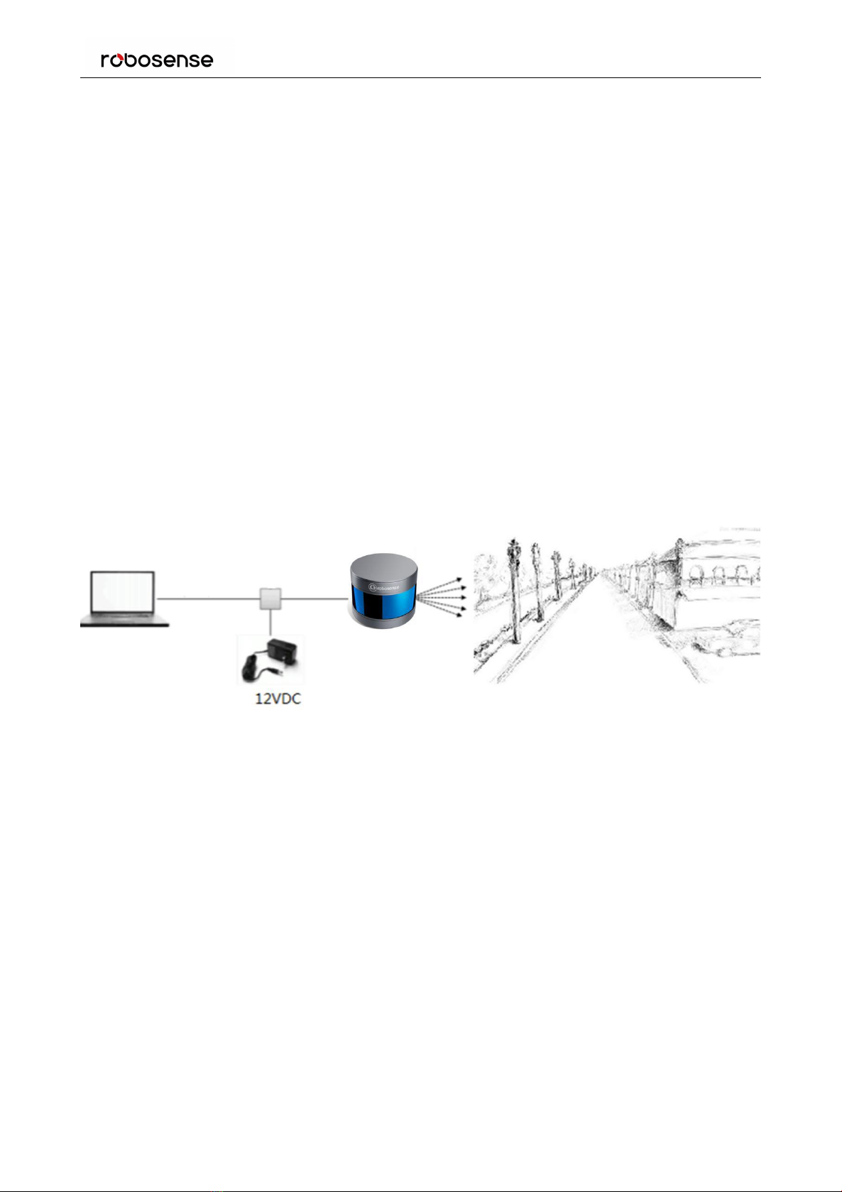
4 Connections................................................................................................................................................... 9
4.1 Power..........................................................................................................................................................9
4.2 Electrical Configuration.............................................................................................................................. 9
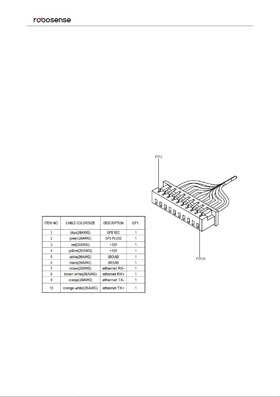
4.3 Electrical Interface......................................................................................................................................9
5 Communications Protocols................................................................................................................................. 11
5.1 MSOP........................................................................................................................................................... 11
5.1.1 Header...........................................................................................................................................12
5.1.2 Data Field.......................................................................................................................................13
5.1.3 Tail..................................................................................................................................................14
5.1.4 Demonstration Data......................................................................................................................15
5.2 DIFOP........................................................................................................................................................ 16
5.3 UCWP........................................................................................................................................................16
6 GPS Synchronization............................................................................................................................................19
6.1 GPS Synchronization Theory.................................................................................................................... 19
6.2 GPS Usage.................................................................................................................................................19
7 Phase Lock........................................................................................................................................................... 20
8 Point Cloud.......................................................................................................................................................... 21
8.1 Coordinate Mapping................................................................................................................................ 21
8.2 Point Cloud Presentation......................................................................................................................... 21
9 Laser Channels and Vertical Angles.....................................................................................................................23
10 Calibrated Reflectivity....................................................................................................................................... 25
11 Trouble Shooting............................................................................................................................................... 26
Appendix A ▪ Point Time Calculate............................................................................................................................28
Appendix B ▪ Information Registers.......................................................................................................................... 29
B.1 Motor(MOT_SPD).................................................................................................................................. 29
B.2 Ethernet(ETH)........................................................................................................................................ 29
B.3 Motor Phase Offset (MOT_PHASE)............................................................................................................. 30
B.4 Top Board Firmware (TOP_FRM).................................................................................................................30
B.5 Bottom Board Firmware (BOT_FRM).......................................................................................................... 30
B.6 Corrected Pitch (COR_PITCH)......................................................................................................................30
B.7 Serial Number(SN)................................................................................................................................. 31
B.8 Software Version(SOFTWARE_VER)...................................................................................................... 31
B.9 UTC Time(UTC_TIME)............................................................................................................................ 31
B.10 STATUS....................................................................................................................................................... 33
B.11 Fault Diagnosis.......................................................................................................................................... 33
B.12ASCII code in GPSRMC Packet....................................................................................................................35
Appendix C ▪ RSView................................................................................................................................................. 36

RS-LiDAR-16 User’s Manual
4
C.1 Features....................................................................................................................................................... 36
C.2 Install RSView.............................................................................................................................................. 36
C.3 Set up Network............................................................................................................................................36
C.4 Visualize Streaming Sensor Data.................................................................................................................37
C.5 Capture Streaming Sensor Data to PCAP File............................................................................................. 38
C.6 Replay Captured Sensor Data from PCAP File.............................................................................................39
C.7 RS-LiDAR-16 Factory Firmware Parameters Setting....................................................................................42
C.8 RSView Data Port.........................................................................................................................................43
C.9 Firmware Online Update.............................................................................................................................44
C.10 Fault Diagnosis.......................................................................................................................................... 45
Appendix D ▪RS-LiDAR-16 ROS Package................................................................................................................. 47
D.1 Prerequisite................................................................................................................................................. 47
D.2 Install RS-LiDAR-16 ROS Package................................................................................................................ 47
D.3 Configure PC IP address.............................................................................................................................. 47
D.4 View the real time data...............................................................................................................................47
D.5 View the recorded pcap file offline............................................................................................................ 48
Appendix E ▪Dimensions........................................................................................................................................ 50
Appendix F LiDAR mechanical installation suggestion..............................................................................................52
Appendix G How to Distinguish the Port Number of MSOP and DIFOP Packets......................................................53

RS-LiDAR-16 User’s Manual
5
Terminologies
MSOP
Main Data Stream Output Protocol
DIFOP
Device Info Output Protocol
UCWP
User Configuration Write Protocol
Azimuth
Horizontal angle of each laser firing
Timestamp
The marker that records the system time
Header
The starting part of the protocol packet
Tail
The ending part of the protocol packet

RS-LiDAR-16 User’s Manual
6
Congratulations on your purchase of a RS-LiDAR-16 Real-Time 3D LiDAR Sensor. Please read carefully before
operating the product. Wish you a pleasurable product experience with RS-LiDAR-16.
1 Safety Notices
To reduce the risk of electric shock and to avoid violating the warranty, do not open sensor body.
Read Instructions - All safety and operating instructions should be read before operating the product.
Follow Instructions - All operating and use instructions should be followed.
Retain Instructions - The safety and operating instructions should be retained for future reference.
Heed Warnings - All warnings on the product and in the operating instructions should be adhered to.
Servicing - The user should not attempt to service the product beyond what is described in the operating
instructions. All other servicing should be referred to RoboSense.

RS-LiDAR-16 User’s Manual
7
2 Introduction
RS-LiDAR-16, launched by RoboSense, is the first of its kind in China, world leading 16-beam miniature LiDAR
product. Its main applications are in autonomous driving, robots environment perception and UAV mapping.
RS-LiDAR-16, as a solid-state hybrid LiDAR, integrates 16 laser/detector pairs mounted in a compact housing.
Unique features include:
Measurement range of up to 150 meters
Within 2 centimeters measurement accuracy
Data rate of up to 320,000 points/second
Horizontal Field of View(FOV) of 360°
Vertical Field of View(FOV) of 30°
The compact housing of RS-LiDAR-16 mounted with 16 laser/detector pairs rapidly spins and sends out
high-frequency laser beams to continuously scan the surrounding environment. Advanced digital signal
processing and ranging algorithms calculate point cloud data and reflectivity of objects to enable the machine to
“see” the world and to provide reliable data for localization, navigation and obstacle avoidance.
Figure 1 RS-LiDAR Imaging System
Operation of device include:
Establish communication with RS-LiDAR-16;
Parse the data packets for azimuth, measured distance, and reported calibrated reflectivities;
Calculate X, Y, Z coordinates from reported azimuth, measured distance, and vertical angle;
Store the data as needed;
Read current device configuration data;
Set Ethernet, time and rotational speed as needed.

RS-LiDAR-16 User’s Manual
8
3 Product Specifications
Table 1 Product Parameters
Sensor
Time of Flight Distance Measurement
16 Channels
Measurement Range: 20cm to 150m (on 20% reflectivity target)
Accuracy: ±2cm (typical)
Field of View (Vertical): ±15.0° (30° in total )
Angular Resolution (Vertical): 2°
Field of View (Horizontal): 360°
Angular Resolution (Horizontal/Azimuth): 0.09°(5Hz) to 0.36°(20Hz)
Rotation Speed: 300/600/1200rpm (5/10/20Hz)
Laser
Class 1
Wavelength: 905nm
Beam Divergence Horizontal: 3.0mrad, Vetical: 1.2mrad
Output
Data Rate: 320,000 points/second
100Mbps Ethernet
UDP packet, include:
Distance
Rotation Angle/Azimuth
Calibrated Reflectivity
Synchronized Timestamp(Resolution: 1us)
Mechanical/
Electrical/
Operational
Power Consumption:9w (typical)
Operating Voltage: 12VDC (with Interface Box and Regulated Power
Supply)9-32VDC
Weight: 0.840Kg(without cable)
Dimensions: 109mm Diameter X 82.7mm Height
Protection Level: IP67
Operation Temperature: -10°C to +60°C

RS-LiDAR-16 User’s Manual
9
4 Connections
4.1 Power
RS-LiDAR-16 can operate with 9 to 32 volt power. But standard 12 volt power is suggested. RS-LiDAR-16 requires
9 watts (typical) of power while operating.
4.2 Electrical Configuration
RS-LiDAR-16 comes with an integral cable(power/data) that is permanently attached to the sensor and
terminates at a standard SH1.1.25 wiring terminal. Figure 2 illustrates the serial pins and their properties.
To operate RS-LiDAR-16, the user should insert the SH1.25 wiring terminal to the corresponding port on the
Interface BOX.
Figure2 Wiring Terminal and Serialized Pin
4.3 Electrical Interface
The Interface BOX provides indicator LEDs for power, interfaces for power, 100Mbps Ethernet, and GPS inputs.
The DC 5.5-2.1 connector for power input, RJ45 Ethernet connector for RS-LiDAR-16 data output and SH1.0-6P
female connector for GPS input. We have two different appearance for the Interface BOX, but the interfaces on

RS-LiDAR-16 User’s Manual
10
the box are the same between the two different Interface BOX. (As shown in Figure 3.)
Figure 3 Interface BOX
Note: When RS-LiDAR-16 connects its grounding system with an external system, the external power supply
system should share the same grounding system with that of the GPS.
On the Interface BOX, the red light indicator means standard power input, and the green one means standard
power output. The Interface BOX access protection status when the red light indicator lights up and green light
indicator blacks out. If the red and green light indicators blink at the same time, please check for errors of the
power supply. If the power supply is checked without error, the high chance is that the Interface BOX is damaged.
Please return damaged Interface BOX to RoboSense for service.
GPS interface definition: GPS REC means GPS UART input, GPS PULSE means GPS PPS input.
Ethernet interface complies with EIA/TIA568 Standard.
Power interface adopts standard DC 5.5-2.1 connector.

RS-LiDAR-16 User’s Manual
11
5Communications Protocols
RS-LiDAR-16 adopts UDP protocol and communicates with computer through 100Mbps Ethernet. There two
different kinds of UDP output packets: MSOP packets and DIFOP packets. The UDP protocol packet in this
manual is of 1290 byte long, and consists of a 1248 byte payload and a 42 byte header. The IP address and port
number of RS-LiDAR-16 is set in the factory as shown in the Table 2, but can be changed by the user as needed.
Table 2 The IP Address and Port Number Set at the Factory
IP Address
MSOP Port No.
DIFOP Port No.
RS-LiDAR-16
192.168.1.200
6699
7788
Computer
192.168.1.102
The default MAC Address of each RS-LiDAR-16 is set in the factory . The MAC Address can be changed as
needed.
To establish communication between a sensor and a computer, the IP address of the computer should be set at
the same network segment of that of the sensor. By default: 192.168.1.102, subnet mask: 255.255.255.0. In case
of uncertainty about the internet setting of the sensor, please set the computer subnet mask as 0.0.0.0, connect
the sensor to the computer, and parse packet to get the IP and port through Wireshark.
RS-LiDAR-16 adopts 3 kinds of communications protocols to establish communication with the computer:
MSOP(Main Data Stream Output Protocol). Distance, azimuth and reflectivity data collected by the sensor
are packed and output to computer.
DIFOP(Device Information Output Protocol). Monitor the current configuration information of the sensor.
UCWP(User Configuration Write Protocol). User can modify some parameters of the sensor as needed.
Table 3 Protocols Adopted by RS-LiDAR-16
Protocol
Abbreviation
Function
Type
Size
Interval
Main Data Stream
Output Protocol
MSOP
Scan Data Output
UDP
1248byte
~1ms
Device Information
Output Protocol
DIFOP
Device Information
Output
UDP
1248byte
~100Mbps
User Configuration
Write Protocol
UCWP
Sensor Parameters
Setting
UDP
1248byte
INF
Note:The following section describes and defines the valid payload (1248 byte) of the UDP protocol packet.
5.1 MSOP
I/O type: device output data, computer parse data.
Default port number is 6699.
MSOP outputs data information of the 3D environment in packets. Each MSOP packet is 1248 bytes long and
consists of reported distance, calibrated reflectivity values, azimuth values and a time stamp.
Each RS-LiDAR-16 MSOP packet payload is 1248 byte long and consists of a 42 byte header and a 1200 byte data
field containing twelve blocks of 100-byte data records and a 6 byte tail.
The basic data structure of a MSOP packet is as shown in Figure 4.

RS-LiDAR-16 User’s Manual
12
MSOP Packet(1248 byte)
6byte
42 byte
data packet
12*100byte= 1200byte
42 byte
(21~30
byte time
stamp)
Header
4byte
reserve+
2byte
(0x00,0x
FF)
Tail
Data block1
0xffee
Azimuth 1
channel data 1
Figure 4 MSOP Packet
5.1.1 Header
The 42 byte Header marks the beginning of data blocks.
In the 42-byte data header , the first 8 bytes are for header identification, the 21 to 30 bytes records time stamp,
the 31st byte represents the LiDAR model, and the rest bytes are reserved for future updates.
The first 8 bytes of the header is defined as 0x55,0xAA,0x05,0x0A,0x5A,0xA5,0x50,0xA0.
Time stamp with a resolution of 1us records the system time. Please refer to the definition of time in Appendix
B.9 and Table 8 in part 3 of this section.
The 31st byte LiDAR model is described as below:
Table 4 LiDAR Model Flag
LiDAR Model (1 byte)
0x01
RS-LiDAR-16
0x02
RS-LiDAR-32
channel data 2
channel data ...
channel data 16
channel data 1
channel data 2
channel data ...
channel data 16
Data block 2
0xffee
0xffee
Azimuth 2
0xffee
Azimuth n
channel data 1
channel data 1
channel data 1
Azimuth12
channel data 2
channel data 2
channel data 2
channel data ...
channel data ...
channel data ...
channel data 16
channel data 16
channel data 16
channel data 1
channel data 1
channel data 1
channel data 2
channel data 2
channel data 2
channel data ...
channel data ...
channel data ...
channel data 16
channel data 16
channel data 16
Data block n
Data block 12

RS-LiDAR-16 User’s Manual
13
5.1.2 Data Field
Data field comprises data blocks that contain valid measurement data. Each data filed contains 12 blocks. Each
block is 100-byte long and is a complete measurement data set. Each data block begins with a 2-byte start
identifier “0xffee”, then a two-byte azimuth value (rotational angle). Each azimuth value records 32 sets of
channel data reported by the 32 laser channels, with data from the upper 16 channels arranged in 1 group and
data from the lower 16 channels arranged in another group. (Please see Section 8 for the relationship between
channel sequence and vertical angel.)
5.1.2.1 Azimuth Value
The reported azimuth is associated with the first laser firing in each sequence of 16 laser firings. The Azimuth
Value is recorded by the encoder. The zero position on the encoder indicates the zero degree of azimuth value
on RS-LiDAR-16. In one data block, there are 32 sets of laser data indicating two sequence of the 16 laser firings,
however only every-other encoder angle is reported for alternate firing sequences. The user can choose to
interpolate that unreported encoder stamp(Refer to 5.1.2.2). The resolution of Azimuth is 0.01°.
For example, in Figure 6, the azimuth value is calculated through the following steps:
Get azimuth values: 0x00,0x44
Combine to a 16 bit, unsigned integer: 0x0044
Convert to decimal: 68
Divided by 100
Result: 0.68°
Hence the firing angle is 0.68°
Note: the position of 0° on sensor is the Y axis positive direction in Figure 8.
5.1.2.2 Azimuth Value Interpolation
Because the RS-LIDAR-16 reports the azimuth value for every-other firing sequence, it’s helpful to interpolate
the un-reported azimuth. There are several ways to interpolate the un-reported azimuth, but the one given
below is simple and straight forward.
Consider a single data packet. The time between the first firing of the first sequence of sixteen firings (Data
Block 1) and the first firing of the third sequence of sixteen laser firings (Data Block 2) is ~100.0µs. If you assume
the rotation speed over that short interval is constant, you can assume the azimuth of the (N+1) set of sixteen
laser firings is halfway between the azimuth reported with the Nth set of 16 laser firings and the azimuth
reported with the (N+2) set of laser firings.
Below is pseudo-code that performs the interpolation. The code checks to see if the azimuth rolled over from
359.99° to 0° between firing sequence N and N+2.
In the example below, N=1.
// First, adjust for a rollover from 359.99° to 0°
If (Azimuth[3] < Azimuth[1])
Then Azimuth[3]:= Azimuth[3]+360;

RS-LiDAR-16 User’s Manual
14
Endif;
// Perform the interpolation
Azimuth[2]:=Azimuth[1]+((Azimuth[3]-Azimuth[1])/2);
// Correct for any rollover over from 359.99° to 0°
If (Azimuth[2]>360)
Then Azimuth[2]:= Azimuth[2]-360;
Endif
5.1.2.3 Channel Data
Channel data contains 3 bytes, with the upper 2 bytes store distance information, and the lower 1 byte contains
reflectivity data. The structure of channel data is as shown in Table 5.
Table 5 Channel Data
The 2-byte distance data is set in centimeter. The distance accuracy is 1 centimeter.
Reflectivity data records relative reflectivity (more definition on reflectivity, please refer to description on
calibrated reflectivity in Section 9 of this manual). Reflectivity data reveals the reflectivity performance of the
system in real measurement environments, it can be used in distinguishing different materials.
The following shows how to parse channel data.
In the case of Figure 6, the distance information is calculated by:
Get distance values: 0x06 ,0x42
Actual distance value: 0x06 , 0x42
Combine distance bytes to a 2-byte, unsigned integer: 0x0642
Convert to decimal: 1602
Divided by 100
Result: 16.02m
Hence the distance measured is 16.02m.
5.1.3 Tail
The tail is 6 bytes long, with 4 bytes unused and reserved for information, and the other 2 byte as: 0x00, 0xFF.
Channel Data N (3 bytes)
2 bytes
Distance
1 byte
Reflectivity
Distance1
[16:8]
Distance2
[7:0]
Reflectivity

RS-LiDAR-16 User’s Manual
15
5.1.4 Demonstration Data
Figure 5 MSOP packet
Figure 6 Data Block

RS-LiDAR-16 User’s Manual
16
5.2 DIFOP
I/O type:device output, computer read.
Default port number is 7788.
DIFOP is a protocol that reports and outputs only device information including the device serial number,
firmware version, driver compatibility, internet setting, calibration data, electrical machine setting and operation
status, fault detection information to users. It is a viewer for users to get comprehensive details about the
device.
Each DIFOP packet is 1248 byte long, and comprises a 8 byte Header, a 1238 byte data field, and a 2 byte tail.
The structure of DIFOP is as shown in Table 6.
Table 6 DIFO Packet
No.
Information
Offset
Length(byte)
Header
0
DIFOP header
0
8
Data
1
motor rotation speed (MOT_SPD)
8
2
2
Ethernet(ETH)
10
26
3
corrected static base (COR_STATIC_BASE)
36
2
4
motor phase lock(MOT_PHASE)
38
2
5
top board firmware version(TOP_FRM)
40
5
6
bottom board firmware version(BOT_FRM)
45
5
7
corrected intensity curves coefficient
50
240
8
reseved
290
2
9
serial number(SN)
292
6
10
reserved
298
3
11
upper computer compatibility
301
2
12
UTC time(UTC_TIME)
303
10
13
operation status(STATUS)
313
18
14
reserved
331
11
15
fault diagnosis(FALT_DIGS)
342
40
16
GPSRMC
382
86
17
corrected static(COR_STATIC)
468
697
18
corrected vertical angle(COR_PITCH)
1165
48
19
reserved
1213
33
Tail
20
tail
1246
2
Note: The Header(the DIFOP identifier) in the table above is 0xA5,0xFF,0x00,0x5A,0x11,0x11,0x55,0x55, among which the first 4
byte 0xA5,0xFF,0x00,0x5A is the sequence to identify the packet.
The tail is 0x0F,0xF0.
For definition of information registers as well as their usage, please check more details in part 2, section 10 of
this manual.
5.3 UCWP
I/O type: computer writes into the device.
Function: user can reconfigure Ethernet connection, time and some parameters of the device.

RS-LiDAR-16 User’s Manual
17
Each UCWP Packet is 1248 byte long, and is comprised of a 8-byte Header, a 1238-byte data field and a 2-byte
Tail.
The UCWP packet structure is as shown below:
Table 7 UCWP Packet
No.
Info
Offset
Length(byte)
Header
0
UCWP header
0
8
Data
1
motor rotation speed
8
2
2
Ethernet
10
26
3
time
36
10
4
reserved
46
2
5
motor phase lock
48
2
6
reserved
50
1196
Tail
7
tail
1246
2
Note: The Header(UCWP identifier) in the table above is 0xAA,0x00,0xFF,0x11,0x22,0x22,0xAA,0xAA, among which, the first 4
bytes 0xAA,0x00,0xFF,0x11 forms the sequence to identify the packet.
The Tail is 0x0F,0xF0.
Statement: RS-LiDAR-16 doesn’t RTC system to support operation while power is off. In the case of no GPS or
GPS signal, it is imperative to write time into the device through a computer, or it will use a default system time
for clock.
Refer to Part 2, Section 10 of this manual for details on Ethernet, Time, Motor Rotation Speed and Motor Phase
Lock.
Below is and example to configure the RS-LIDAR-16 :
LiDAR IP: 192.168.1.105,
Destination PC IP: 192.168.1.225,
MAC_ADDR: 001C23174ACC
MSOP port: 6688
DIFOP port: 8899
Time: 09:45:30:100:200, March 10, 2017
Rotation speed: 600rpm
Motor phase lock: 90 degree
User can reset the above information by following the example in Table 8.
Table 8 Resetting Example
Information
Content
Setting
Length(byte)
Header
0xAA,0x00,0xFF,0x11,
0x22,0x22,0xAA,0xAA
8
Rotate Speed
1200rpm
0x04
0xB0
2
LiDAR IP
(LIDAR_IP)
192.168.1.105
0xC0
0xA8
4

RS-LiDAR-16 User’s Manual
18
0x01
0x69
Destination PC IP
(DEST_PC_IP)
192.168.1.225
0xC0
0xA8
0x01
0xE1
4
Device MAC Address
(MAC_ADDR)
001C23174ACC
0x00,0x1C,0x23,
0x17,0x4A,0xCC
6
MSOP Port(port1)
6688
0x1A20
2
MSOP Port(port2)
6688
0x1A20
2
DIFOP Port(port3)
8899
0x22C3
2
DIFOP Port(port4)
8899
0x22C3
2
port5~port6
00,00,00,00,
0x00,0x00,0x00,0x00,
4
UTC_TIME
Year:2017
Month:3
Day:10
Hour:9
Minute:45
Second:30
Millisecond: 100
Microsecond: 200
0x11
0x03
0x0A
0x09
0x2D
0x1E
0x00,0x64
0x00,0xC8
10
Others
reserved
0x00
2
Motor Phase Lock
90
0x005A
2
Others
reserved
0x00
1196
Tail
0x0F,0xF0
2
While setting the device and computer according to this protocol, it is imperative to set all the information listed
in the table above. Addressing or writing in with part of the information will lead to invalid setting. The function
refreshes the moment the correspondent parameter is changed, but the network parameters only take effect
when the next initialization of device is started.
RSVIEW provides the configuration UI, so we suggest to use RSVIEW to configure the RS-LiDAE-16.

RS-LiDAR-16 User’s Manual
19
6 GPS Synchronization
RS-LiDAR-16 supports external GPS receiver connections. With GPS connections, we can synchronize the
RS-LiDAR-16 system time and also pack the GPSRMC message into DIFOP packets.
6.1 GPS Synchronization Theory
The GPS receiver keeps generating synchronization Pulse Per Second (PPS) signal and GPSRMC message and
send them to the sensor. It takes 20ms to 200ms to generate a PPS signal, and the GPSRMC message should be
received within 500ms after the PPS signal is generated.
6.2 GPS Usage
The GPS interface on the Interface BOX is SH1.0-6P female connector, the pin definition is as shown in Figure 3.
Pin GPS REC receive the data that is 3.3V TTL standard from GPS module serial port.
Pin GPS PULSE receive the PPS from GPS module.
Pin +5V can supply the power for GPS module. (Please do not connect the GPS into the +5V pin if the GPS is 3.3V
power supply)
Pin GND provide the ground connection for GPS module.
The GPS module should set to 9600bps baud rate, 8 bit data bit, no parity and 1 stop bit. RS-LiDAR-16 only read
the GPSRMC message from GPS module., the GPSMRC message format is shown as below:
$GPRMC,<1>,<2>,<3>,<4>,<5>,<6>,<7>,<8>,<9>,<10>,<11>,<12>*hh
<1> UTC time
<2> validity - A-ok, V-invalid
<3> Latitude
<4> North/South
<5> Longitude
<6> East/West
<7> Ground Speed
<8> True course
<9> UTC date
<10> Variation
<11> East/West
<12> Mode (A/D/E/N=)
*hh checksum from $ to *
Different GPS module may send out different length GPSRMC message, the RS-LiDAR-16 reserve 86byte space
for GPRMC message, so it can be compatible with the majority GPS module in the market.
Other manuals for RS-LiDAR-16
1
Table of contents
Other RoboSense Accessories manuals