RoboSense RS-Bpearl User manual

RS-Bpearl User Manual

RS-Bpearl User Manual
I
Revision History
Revision Number
Description
Date
Edited by
1.0
Initial release
2019-08-14
PD
2.0
Update Figure
Update dimension
Update power consumption
Update RSView Guide in Appendix C
Update Appendix A
Update footnote of Product Specification
Update table of correspondence between
laser channel and vertical angle
2019-12-11
PD
2.0.1
Update dimension drawing in Appendix E
Modify some not precise description
2020-02-18
PD

RS-Bpearl User Manual
II
Terminology
MSOP
Main data Stream Output Protocol
DIFOP
Device Info Output Protocol
UCWP
User Configuration Write Protocol
Azimuth
Horizontal Angle of LiDAR
Timestamp
Time Point of Encapsulation of a UDP Packet
Header
The Header of a UDP packet
Tail
The Tail of a UDP packet

RS-Bpearl User Manual
III
TABLE of CONTENT
Revision History................................................................................................................................. I
Terminology....................................................................................................................................... II
1. Safety Notice.................................................................................................................................1
2. Introduction....................................................................................................................................2
3. Product Specifications.................................................................................................................3
4. Interface......................................................................................................................................... 4
4.1 Power Supply..................................................................................................................... 4
4.2 Data Output interface of LiDAR.......................................................................................4
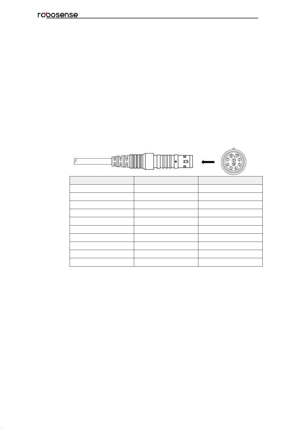
2.3 Interface Box.......................................................................................................................4
2.4 Connection of Interface Box.............................................................................................6
5. Communication Protocol.............................................................................................................7
5.1 MSOP.................................................................................................................................. 7
5.1.1 Header......................................................................................................................9
5.1.2 Data Field.............................................................................................................. 10
5.1.3 Tail........................................................................................................................... 11
5.1.4 MSOP Data Package...........................................................................................11
5.2DIFOP................................................................................................................................. 12
5.3UCWP................................................................................................................................. 13
6. GPS Synchronization................................................................................................................ 16
6.1 GPS Synchronization Theory........................................................................................ 16
6.2 GPS Usage....................................................................................................................... 16
7. Key Characteristic...................................................................................................................... 17
7.1 Return Mode..................................................................................................................... 17
7.1.1 Return Mode Principle......................................................................................... 17
7.1.1The Strongest Return........................................................................................... 17
7.1.2Strongest, Last and Dual Returns...................................................................... 17
7.1.3Return Mode Flag..................................................................................................17
7.2 Phase Lock....................................................................................................................... 18
8. Point Cloud..................................................................................................................................19
8.1 Coordinating Mapping.....................................................................................................19
9. Definition of Vertical Angles......................................................................................................20
10. Reflectivity................................................................................................................................. 22
11. Troubleshooting........................................................................................................................ 23
Appendix A Point Time Calculate.................................................................................................24
A.1 RS-Bpearl Calculation of time stamp in single mode................................................24
A.2 RS-Bpearl Calculation of time stamp in dual mode...................................................26
Appendix B Information Registers............................................................................................... 28
B.1 Motor(MOT_SPD)........................................................................................................... 28
B.2 Ethernet(ETH).................................................................................................................. 28
B.3 FOV Setting (FOV SET)................................................................................................. 29
B.4 Motor Phase Offset (MOT_PHASE).............................................................................29

RS-Bpearl User Manual
IV
B.5 Top Board Firmware (TOP_FRM).................................................................................29
B.6 Bottom Board Firmware (BOT_FRM).......................................................................... 30
B.7 Serial Number(SN)..........................................................................................................30
B.8 Software Version(SOFTWARE_VER)......................................................................... 30
B.9 UTC Time(UTC_TIME)................................................................................................... 30
B.10 STATUS.......................................................................................................................... 31
B.11 Fault Diagnosis.............................................................................................................. 32
B.12 ASCII code in GPRMC Packet................................................................................... 33
B.13 Corrected Vertical Angle (COR_VERT_ANG)..........................................................33
B.14 Corrected Horizontal Offset Angle (COR_HOR_ANG)...........................................34
Appendix C RSView....................................................................................................................... 35
C.1 Software Features...........................................................................................................35
C.2 Installation of RSView.................................................................................................... 35
C.3 Network Setup................................................................................................................. 35
C.4 Visualization of point cloud............................................................................................ 35
C.5 Save Streaming Sensor Data into PCAP File............................................................ 37
C.6 Replay Recorded Sensor Data from PCAP Files...................................................... 37
C.7 RS-Bpearl Factory Firmware Parameters Setting.....................................................39
C.8 Setting RSView Data Port..............................................................................................41
C.9 Firmware Update Online................................................................................................ 41
C.10 Troubleshooting by Fault Diagnosis.......................................................................... 42
Appendix D RS-Bpearl ROS Package........................................................................................44
D.1 Software Installation....................................................................................................... 44
D.2 Compile RS-Bpearl ROS Package.............................................................................. 44
D.3 Configure PC IP address............................................................................................... 44
D.4 Display of the real-time data......................................................................................... 44
D.5 Offline Display the recorded PCAP File...................................................................... 45
Appendix E Dimension.................................................................................................................. 47
Appendix F Suggestion of Mechanical LiDAR Mount.............................................................. 48
Appendix G Seek MSOP and DIFOP Port Number..................................................................49
Appendix H Clean of LiDAR......................................................................................................... 50
H.1 Attention............................................................................................................................ 50
H.2 Required Materials.......................................................................................................... 50
H.3 Clean Method................................................................................................................... 50

1
RS-Bpearl User Manual
Congratulations on your purchase of a RS-Bpearl Real-Time 3D LiDAR Sensor. Please
read carefully before operating the product. Wish you have a pleasurable product
experience with RS-Bpearl.
1. Safety Notice
In order to reduce the risk of electric shock and to avoid violating the warranty, do not
open sensor housing.
Laser safety - The laser safety complies with IEC60825-1:2014.
Read Instructions - All safety and operating instructions should be read before
operating the product.
Follow the Instructions - All operating and use instructions should be followed.
Retain Instructions - The safety and operating instructions should be retained for
future reference.
Heed Warnings - All warnings on the product and in the operating instructions should
be adhered to.
Maintenance - The user should not attempt to maintain the product beyond what is
described in the operating instructions. All other Maintenance should be referred to
RoboSense.

2
RS-Bpearl User Manual
2. Introduction
RS-Bpearl, the close-range LiDAR developed by RoboSense, is the world leading LiDAR
for monitoring blind spot. It is particular utilized in and perception of environment for
autonomous driving.
RS-Bpearl is realized by solid-state hybrid LiDAR. The technical details are listed below:
Minimum measuring range: 10 cm
Accuracy: within up to ± 2 centimeter
Data rate up to 576,000 points/second
Horizontal field of view (FOV) of 360°
Vertical field of view (FOV) of 90°
Figure 1:Representation of RS-Bpearl Imaging.
The operating Instructions of LiDAR:
Connecting the device of RS-Bpearl;
Parsing the data packets, in order to capturing the values of azimuth, measuring
distance and calibrated reflectivity;
Calculate X, Y, Z coordinates from reported azimuth, measured distance, and vertical
angle;
Storing the data of point cloud according to demand;
Checking the status of set-up information of device;
Resetting the status of network configuration, timing and rotation speed according to
demand.

3
RS-Bpearl User Manual
3. Product Specifications1
Table 1: Product Parameters.
Sensor
TOF measuring distance, including the reflectivity
Range: from 0.1 m to 30m (Reflectivity: 10%)2
Accuracy: ±3cm (typical value)3
FOV(vertical): 90°
FOV (horizontal): 360°
Angle resolution (horizontal/ azimuth): 0.2° (10 Hz)/0.4° (20 Hz)
Rotation speed: 600/1200 rpm (corresponding to 10/20 Hz)
Laser
Class 1
Wave length: 905nm
Full angle of beam divergence: horizontal 9 mrad, vertical 17.8 mrad
Output
Date rate: ~600k points/second
100M Ethernet
Communication protocol: UDP
The Information that is included in Dates Segment:
Distance
Rotation angle/Azimuth Calibrated
reflectivity
Synchronized timestamp (Timer resolution 1 us)
Mechanical/
Electrical/
Operational
Power consumption: 13 W(typical)4
Working voltage: 9-32 VDC
Weight: 0.92 kg (without cable)
Dimensions: Diameter 100 mm × Height 111 mm
Ingress Protection Rating: IP67
Operation temperature: -30 ℃~+60 ℃5
Storage temperature: -40 ℃~+85 ℃
1The following data is only for mass-produced products. Any sample, testing machine and other
non-mass-produced versions may not be referred to this specification. If you have any questions, please
contact RoboSense sales.
2The measurement target of range is a 10% NIST Diffuse Reflectance Calibration Targets, the test
performance is depending on circumstance factors, not only temperature, range and reflectivity but also
including other uncontrollable factors.
3The measurement target of accuracy is a 50% NIST Diffuse Reflectance Calibration Targets, the test
performance is depending on circumstance factors, not only temperature, range and reflectivity but also
including other uncontrollable factors.
4The test performance of power consumption is depending on circumstance factors, not only
temperature, range and reflectivity but also including other uncontrollable factors.
5Device operating temperature is depending on circumstance, including but not limited to ambient
lighting, air flow and pressure etc.

4
RS-Bpearl User Manual
4. Interface
4.1 Power Supply
A voltage transform module is already integrated in RS-Bpearl. The supply voltage could
keep in the range of 9~32 VDC with utilization of Interface-Box. The recommend supply
voltage is 12 VDC. The operating power consumption is about 13 W (typical).
4.2 Data Output interface of LiDAR
The data output access of RS-Bpearl is physically protected by an aviation terminal
connector. From the LiDAR to the aviation connector the cable length is 1 meter. The pins
of the aviation terminal connector are defined as follow:
PIN
Wire Color
Function
1
Red
+12V
2
Yellow
+12V
3
White
GROUND
4
Black
GROUND
5
Green
GPS PULSE
6
Blue
GPS REC
7
Brown
LiDAR Ethernet RX+
8
Brown white
LiDAR Ethernet RX-
9
Orange
LiDAR Ethernet TX+
10
Orange white
LiDAR Ethernet TX-
Figure 2: Aviation Connector PIN Number.
4.3 Interface Box
In order to connect the RS-Bpearl conveniently, there is an interface box provided.
There are accesses for power supply, Ethernet and GPS on Interface Box. Meanwhile
there are also indicator LEDs for checking the status of power supply.
For those accesses, an SH1.0-6P female connector is the interface for GPS signal input.
Another interface is a DC 5.5~2.1 connector for power input. The last one is a Rj45
Ethernet connector for RS-Bpearl data transport. The length of the integral cable is 3 m,
when the cable length needs to be shorten or extended, please contact RoboSense
technical support, as shown in Figure 3.

5
RS-Bpearl User Manual
PIN
Function
1
GPS PULSE
2
+5V
3
GND
4
GPS REC
5
GND
6
NC
Figure 3: Interface Definition Interface Box.
Note: When RS-Bpearl connects its grounding system with an external system, the
external power supply system should share the same grounding system with that of the
GPS.
When the power input is in order, the red LED which indicates the power input status will
be lighted. Meanwhile the green LED which indicates the power output status will be
lighted, when the power output is in order. While red LED is bright and green LED is dark,
Interface Box is in Protection status. While red and green LEDs are all dark, please check
whether the power supply is out of order or damaged. If it is intact, that could prove that
the Interface Box is damaged. Please send the damaged Interface Box back to
RoboSense Service.
GPS interface definition: GPS REC stands for GPS input; GPS PULSE stands for GPS
PPS input.
Interface of power supply is standard DC 5.5-2.1 connector.

6
RS-Bpearl User Manual
4.4 Connection of Interface Box
Figure 4: Diagram of Interface Box Connection.

7
RS-Bpearl User Manual
5. Communication Protocol
RS-Bpearl adopts IP/UDP protocol and communicates with computer through Ethernet. In
this User Guide, The UDP protocol packet in this manual is of 1290 byte long and consists
of a 1248-byte valid payload and a 42-byte header. The IP address and port number of
RS-Bpearl is set in the factory as shown in the Table 2, but can be changed by the user as
needed.
Table 2: The IP Address and Port Number Set in the Factory.
Device
IP Address
MSOP Port No.
DIFOP Port No.
RS-Bpearl
192.168.1.200
6699
7788
PC
192.168.1.102
The default MAC Address of each RS-Bpearl is already set up in the factory with
uniqueness. In order to establishing the communication between a RS-Bpearl and a
computer, the IP Address of the computer should be set at the same network segment.
For instance, IP Address is 192.168.1.X (X can be taken by a value from 1~254), subnet
mask: 255.255.255.0. If the internet setting of the sensor is unknown, please set the
subnet mask as 0.0.0.0, connect the sensor to the computer, and capture UDP packet to
get the information of IP and Port through Wireshark.
RS-Bpearl adopts 3 kinds of communication protocols to establish communication with the
computer:
MSOP (Main Data Stream Output Protocol). Distance, azimuth and reflectivity
data collected by the sensor are packed and output to computer;
DIFOP (Device Information Output Protocol). Monitor the current
configuration information of the sensor;
UCWP (User Configuration Write Protocol). User can modify some
parameters of the sensor as needed.
Table 3: Overview of the MSOP.
Note: In the following chapters only the valid payload (1248 byte) will be discussed.
5.1 MSOP
MSOP is the abbreviation of Main Data Stream Output Protocol. I/O type: device output
data, computer parse data.
Default port number is 6699.
MSOP outputs data information of the 3D environment in packets. Each MSOP packet is
1248 bytes long and consists of reported distance, calibrated reflectivity values, azimuth
values and a timestamp.
In each RS-Bpearl MSOP packet, payload is 1248-byte long and consists of a 42-byte
header and a 1200-byte data field containing twelve blocks of 100-byte data records and a
6-byte tail. The basic data structure of a MSOP packet for single return is as shown in
Figure 5:
Protocol
Abbreviation
Function
Type
Size
Interval
Main data Stream Output Protocol
MSOP
Scan Data Output
UDP
1248 bytes
~0.66 ms
Device Information Output Protocol
DIFOP
Device Information Output
UDP
1248 bytes
~100 ms
User Configuration Write Protocol
UCWP
Sensor Parameters Setting
UDP
1248 bytes
INF

8
RS-Bpearl User Manual
Figure 5: Single Return MSOP.

9
RS-Bpearl User Manual
First
return
Second
return
The basic data structure of a MSOP packet for dual return is as shown in
Figure 6.
Figure 6: Dual Return MSOP.
5.1.1 Header
The 42-byte Header marks the beginning of data blocks.
In the 42-byte data header, the first 8 bytes are for header identification, the 21st to 30th byte
records timestamp, and the rest bytes are reserved for future updates.
The first 8 bytes of the header is defined as 0x55, 0xAA, 0x05, 0x0A, 0x5A, 0xA5, 0x50, 0xA0.
Time stamp with a resolution of 1us records the system time. Please refer to the definition of
time in Appendix B.9 and Table 6 in section 5.3 of this chapter.

10
RS-Bpearl User Manual
5.1.2 Data Field
Data field comprises data blocks that contain valid measurement data, in total 1200 bytes.
Each data filed contains 12 blocks, each block is 100-byte long and is a complete
measurement data set. Each data block begins with a 2-byte start identifier “0xffee”, then
a two-byte azimuth value (rotational angle). Each azimuth value records 32 sets of
channel data reported by the 32 laser channels. (Please see chapter 9 for the relationship
between channel sequence and vertical angel)
5.1.2.1 Azimuth Value
The reported azimuth is associated with the first laser firing in each sequence of laser
firings. The Azimuth Value is recorded by the encoder. The zero position on the encoder
indicates the zero degree of azimuth value on RS-Bpearl. The resolution of Azimuth is
0.01°.
For example, in Figure 8, the azimuth value is calculated through the following steps:
Get azimuth values: 0x61, 0x86
Combine to a 16 bit, unsigned integer: 0x6186 Convert to decimal: 24966
Divided by 100
Result: 249.66°
Hence,the firing angle is 249.66°
5.1.2.2 Channel Data
Channel Data contains 3 bytes, with the upper 2 bytes (16 bits in total) store distance
information, and the lower 1 byte contains reflectivity data. The structure of channel data
is as shown in Table 4.
Table 4:Channel Data Definition.
Channel data n (3 byte)
2-byte Distance
1-byte Reflectivity
Distance1 [15:8]
Distance2 [7:0]
Reflectivity Information
The 2-byte distance data is set in centimeter. The distance resolution is 0.5 cm. The
following shows how to parse channel data:
For example, in the case of Figure 8, the distance information is calculated by:
Get distance values: 0x01, 0xb4.
0x01 is the upper byte of distance, concert to decimal: 1.
0xb4 is the lower byte of distance, convert todecimal: 180.
Hence, distance= upper byte of distance * 256 + lower byte of distance
= 1*256 + 180 = 436.
According to distance resolution, the distance: 435 * 0.05 = 2.18 m.
Hence, the measured distance is 2.18 m.

11
RS-Bpearl User Manual
5.1.3 Tail
The tail is 6 bytes long, with 4 bytes unused and reserved for other information, and the
other 2 bytes as: 0x00, 0xFF.
5.1.4 MSOP Data Package
The following Figure 8 shows the format of MSOP data packet and relevant parsing
processes.
Figure 7: MSOP Packet.

12
RS-Bpearl User Manual
Figure 8: Details of MSOP Packet.
5.2 DIFOP
DIFOP is abbreviation of Device Info Output Protocol. I/O type:device output, computer
read.
Default port number is 7788.
DIFOP is a protocol that reports and outputs only device information including the device
serial number, firmware version, driver compatibility, internet setting, calibration data,
electrical machine setting and operation status, fault detection information to users. It is a
viewer for users to get comprehensive details about the device.
Each DIFOP packet is 1248 bytes long, and comprises an 8-byte Header, a 1238-byte
data field, and a 2-byte tail.
The structure of DIFOP is as shown in Table 5.

13
RS-Bpearl User Manual
Table 5: DIFOP Packet Definition.
Segment
No.
Information
Offset
Length/byte
Header
0
DIFOP header
0
8
Data
1
Motor rotation speed (MOT_SPD)
8
2
2
Ethernet (ETH)
10
22
3
FOV setting
32
4
4
Reserved
36
2
5
Motor phase lock (MOT_PHASE)
38
2
6
Top board firmware version (TOP_FRM)
40
5
7
Bottom board firmware version
(BOT_FRM)
45
5
8
Reserved
50
242
9
Serial number (SN)
292
6
10
Zero angle offset
298
2
11
Return mode
300
1
12
Upper computer compatibility
301
2
13
UTC time (UTC_TIME)
303
10
14
Operation status (STATUS)
313
18
15
Reserved
331
11
16
Fault diagnosis (FALT_DIGS)
342
40
17
GPRMC
382
86
18
Corrected vertical angle
468
96
19
Corrected horizontal angle
564
96
20
Reserved
660
586
Tail
21
Tail
1246
2
Note: The Header (the DIFOP identifier) in the table above is 0xA5, 0xFF, 0x00, 0x5A,
0x11, 0x11, 0x55, 0x55, among which the first 4 byte 0xA5, 0xFF, 0x00, 0x5A is the
sequence to identify the packet.
The tail is 0x0F, 0xF0.
For definition of information registers as well as their usage, please check more details in
Appendix B of this manual.
5.3 UCWP
I/O type: computer writes into the device.
Function: user can reconfigure Ethernet connection, time and some parameters of the
device.
Each UCWP Packet is 1248 bytes long, and is comprised of a 8-byte Header and a
40-byte data field.
The UCWP packet structure is as shown in Table 6 below:

14
RS-Bpearl User Manual
Table 6: UCWP Packet Definition.
Segment
No.
Information
Offset
Length/byte
Header
0
UCWP header
0
8
Data
1
Motor rotation speed
8
2
2
Ethernet
10
22
3
FOV setting
32
4
4
Time
36
10
5
Motor phase lock
46
2
Note: The Header (UCWP identifier) in the table above is 0xAA, 0x00, 0xFF, 0x11,
0x22, 0x22, 0xAA, 0xAA, among which, the first 4 bytes 0xAA, 0x00, 0xFF, 0x11
forms the sequence to identify the packet.
Statement: RS-Bpearl doesn’t RTC system to support operation while power is off. In the
case of no GPS or GPS signal, it is imperative to write time into the device through a
computer, or it will use a default system time for clock.
Refer to Part 2, Section 10 of this manual for details on Ethernet, Time, Motor Rotation
Speed and Motor Phase Lock.
Table 7: An Example for corresponding value of Setting.
Information
Content
Setting
Length/byte
Header
0xAA,0x00,0xFF,
0x11,0x22,0x22,
0xAA,0xAA
8
Rotate Speed
600rpm
0x02
0x58
2
LiDAR IP
(LIDAR_IP)
192.168.1.105
0xC0
0xA8
0x01
0x69
4
Destination PC IP
(DEST_PC_IP)
192.168.1.225
0xC0
0xA8
0x01
0xE1
4
Device MAC Address
(MAC_ADDR)
001C23174ACC
0x00,0x1C,0x23,
0x17,0x4A,0xCC
6
MSOP Port(port1)
6688
0x1A20
2
MSOP Port(port2)
6688
0x1A20
2
DIFOP Port(port3)
8899
0x22C3
2
DIFOP Port(port4)
8899
0x22C3
2
FOV start angle
0
0x0000
2
FOV end angle
12000
0x2EE0
2

15
RS-Bpearl User Manual
UTC_TIME
Year:2017
Month:3
Day:10
Hour:9
Minute:45
Second:30
Millisecond: 100
Microsecond: 200
0x11
0x03
0x0A
0x09
0x2D
0x1E
0x00,0x64
0x00,0xC8
10
Motor Phase Lock
90
0x005A
2
While setting the device and computer according to this protocol, it is imperative to set all
the information listed in the table above. Addressing or writing in with part of the
information will lead to invalid setting. The function refreshes the moment the
correspondent parameter is changed, but the network parameters only take effect when
the next initialization of device is started.
RSVIEW provides the configuration UI, so we suggest to use RSVIEW to configure the
RS-Bpearl. When performing the parameter writing process, please keep the power
connection for LiDAR and make sure the parameter writing is done when we want to
power off the LiDAR, otherwise there is a risk of parameter configuring error.
Table of contents
Other RoboSense Accessories manuals
Popular Accessories manuals by other brands

Domi Jump
Domi Jump TRAMPOLINE BASKETBALL HOOP Installation Manual & Safety Instructions

Acuity Controls
Acuity Controls nLight nCM ADCX RJB Installation sheet

AECO
AECO SMS88-P5 2NC H1C PL quick start guide

Panasonic
Panasonic PX-2 Series manual

Alula
Alula DWS-LL quick start guide

Clip Sonic
Clip Sonic TEA134 instructions