8
Settings
REMOTE SETUP
Press the encoder button to enter the REMOTE SETUP menu. Press the
encoder button to enter the local info. It will display the source unit’s
model number, I.D. number, Revision, and if the flash is up to date. Press
the encoder button to return to REMOTE SETUP menu. Rotate then press
the encoder button to enter the device pairing menu. Follow directions
displayed on the source unit to complete pairing. Press the menu button
to return to the REMOTE SETUP menu and rotate then press the encoder
button to enter the Head Unit Reset to clear the memory and restore it to
factory settings. Once a remote is paired to the unit DISCONNECT will
also be displayed in the REMOTE SETUP menu. To disconnect a paired
remote, rotate then press the encoder button on disconnect.
SOFTWARE
VERSION - Press the encoder button to display the current firmware
version of the unit.
UPDATE - Press the encoder button to update the firmware. Follow the
instructions on the screen when updating.
FACTORY DEFAULT
AUDIO – Press the encoder button to access. Rotate the encoder button
to select YES/NO. Selecting YES will reset your unit back to factory
default settings.
SYSTEM - Press the encoder button to access. Rotate the encoder button
to select YES/NO. Selecting YES will reset your unit back to factory
default settings.
Basic Operation
TURNING THE UNIT ON / OFF
Press and hold the SRC (Power) button to turn the unit ON or OFF
ADJUSTING THE VOLUME
Rotate encoder knob left or right to desired volume level (0-40). The
current volume level will be displayed during adjustment.
ADJUSTING THE SUBWOOFER OUTPUT
Press the SUB + or SUB- buttons to adjust the output level (0-20).
ADJUSTING THE SCREEN BRIGHTNESS
Press the SCREEN BRIGHTNESS button to adjust the brightness level.
There are two brightness levels.
SELECTING A SOURCE TO PLAY
Press the SRC button to show the different source options (FM
TUNER>AM TUNER>WB TUNER>USB>AUX>BLUETOOTH). Use the
rotary encoder or press the SRC button to scroll through sources.
Tuner Operation (FM/AM/WB)
To operate, use the rotary encoder to select the tuner source you want to
listen to (FM>AM>WB).
To AUTO SEEK stations, press the FWD and REV buttons. To MANUAL
SEEK stations, press and hold the FWD and REV buttons to tune to the
desired frequency.
To MUTE the TUNER, press the PLAY/PAUSE button.
FM BAND SETTINGS
To access the FM BAND SETTINGS, press the MENU when using the FM
TUNER source. This will give you access to the settings specific to the
FM TUNER (FM>PRESETS>ADD PRESETS>REMOVE PRESETS>AUTO
STORE>LOCAL).
PRESETS
Press the encoder button to access the PRESETS list. Using this feature
allows you to see what PRESETS are saved on the unit.
ADD PRESETS
Press the encoder button on the ADD PRESETS option. You will need
to be on both the station and PRESET group you want to add first
(FM1>FM2>FM3). Using this feature allows you to save stations to the
unit. Once selected, use the rotary encoder to select the PRESET number
(1-6) you want the station saved to.
REMOVE PRESETS
Press the encoder button on the REMOVE PRESETS option. You
will need to be under the PRESET group you want to adjust first
(FM1>FM2>FM3). Using this feature allows you to remove saved
stations on the unit. Once selected, use the rotary encoder to select the
PRESET number (1-6) of the station you want removed.
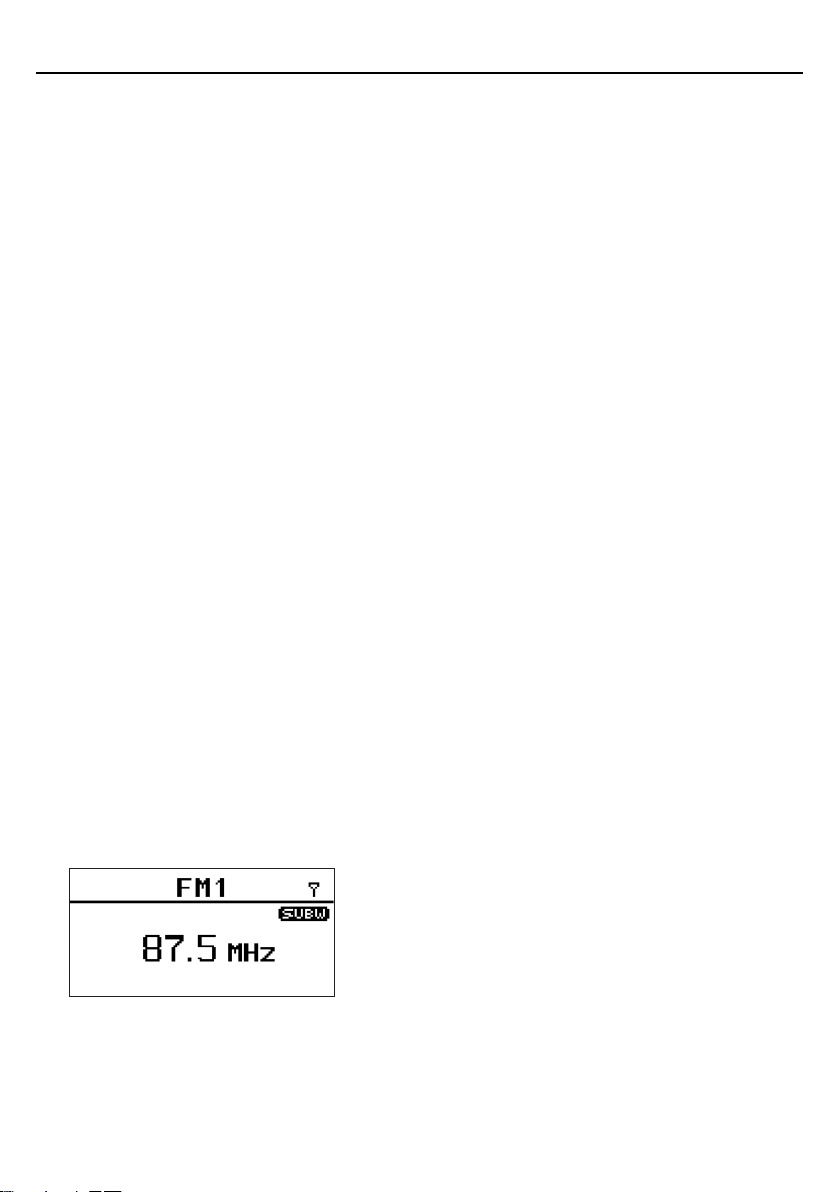
FM
Press the encoder button to access the FM PRESET options
(FM1>FM2>FM3). Using this feature allows you to have separate tuner
preset groups to choose from. Use the rotary encoder button to scroll
through the TUNER groups and press to select the group.
AUTO STORE
Press the encoder button to access the AUTO STORE function. You
will need to be under the PRESET group you want to adjust first
(FM1>FM2>FM3). This feature automatically stores presets on the unit.
It will stop when presets 1-6 are set. Select the next PRESET group and
repeat to fill next set.
LOCAL
Press the encoder button to access the LOCAL options. Once selected,
use the rotary encoder to select ON or OFF. The local option tunes to
nearby radio stations with sufficiently strong signals for good reception.
In areas where reception is poor, switching to distance tuning enables the
unit to tune in to more distant stations. Distance tuning is the default.
AM BAND SETTINGS
To access the AM BAND SETTINGS, press the MENU when using the AM
TUNER source. This will give you access to the settings specific to the
AM TUNER (AM>PRESETS>ADD PRESETS>REMOVE PRESETS>AUTO
STORE>LOCAL).
PRESETS
Press the encoder button to access the PRESETS list. Using this feature
allows you to see what PRESETS are saved on the unit.
ADD PRESETS
Press the encoder button on the ADD PRESETS option. You will need
to be on both the station and PRESET group you want to add first
(AM1>AM2). Using this feature allows you to save stations to the unit.
Once selected, use the rotary encoder to select the PRESET number (1-6)
you want the station saved to.
REMOVE PRESETS
Press the encoder button on the REMOVE PRESETS option. You will
need to be under the PRESET group you want to adjust first (AM1>AM2).
Using this feature allows you to remove saved stations on the unit. Once
selected, use the rotary encoder to select the PRESET number (1-6) of
the station you want removed.
AM
Press the encoder button to access the FM PRESET options (AM1>AM2).