roco Z21-Booster User manual

10805
Z21-Booster
Deutsch ................................. 2 – 9
English ................................. 10 – 17
Français ................................. 18 – 25
8010805920 V_2016.indd 1 15.04.2016 10:51:04

2
D
8010805920 V_2016.indd 2 15.04.2016 10:51:05

3
D
Wichtige Hinweise
• Wenn Sie den Z21-Booster mit Produkten von Drittherstellern kombinieren, besteht keine
Gewährleistung bei Beschädigungen oder Felhfunktionen.
• Der Z21-Booster darf auf keinen Fall mit Wechselspannung versorgt werden.
• Verwenden Sie pro Z21-Booster ein eigenes Netzteil, es ist sonst leicht möglich, dass ein unzulässiger
Masseschluss entsteht, der Ihren Z21-Booster oder andere Digitalkomponenten zerstören könnte!
• Verwenden Sie den Z21-Booster nicht, wenn der Netzstecker, das Netzkabel oder das Gerät selbst
defekt oder beschädigt ist.
• Führen Sie Anschlussarbeiten nur bei abgeschalteter Betriebsspannung durch.
• Durch das Öffnen des Z21-Booster-Gehäuses erlischt jeder Anspruch auf Gewährleistung.
• Arbeiten Sie vorsichtig und achten Sie beim Anschluss an das Gleissystem darauf, dass keine Kurzschlüsse
enstehen! Ein falscher Anschluss kann die Digitalkomponenten zerstören. Lassen Sie sich gegebenfalls von Ihrem
Fachhändler beraten.
• Während des Betriebes kann es zu einer Erwärmung des Z21-Booster kommen. Achten Sie auf genügenden
Abstand zu benachbarten Teilen, um ausreichende Lüftung und Kühlung des Gerätes zu
gewährleisten.
• Lassen Sie Ihre Modellbahnanlage niemals unbeaufsichtigt in Betrieb! Bei einem unbemerkt auftretenden
Kurzschluss besteht Brandgefahr durch Erwärmung!
Herzlichen Dank, dass Sie sich für einen Z21-Booster
von Roco und Fleischmann entschieden haben!
Auf den folgenden Seiten verraten wir Ihnen, was Sie wissen müssen, um den Z21-Booster an
Ihre Anlage anzuschließen und in Betrieb zu nehmen. Außerdem nden Sie in diesem Handbuch
viele praktische Tipps. Bitte lesen Sie diese Anleitung und Warnhinweise vor der Inbetriebnahme
sorgfältig durch. Obwohl der Z21-Booster sehr robust konstruiert ist, kann ein falscher
Anschluss oder eine Fehlbedienung zu einer dauerhaften Beschädigung des Gerätes führen.
8010805920 V_2016.indd 3 15.04.2016 10:51:05

4
D
Kurzanleitung
Taster Normalbetrieb:
• kurz drücken:
wechseln zwischen Normalbetrieb und STOP
•halten bis „Config“ blinkt (min. 3s):
Konfigurationsmodus
• halten bis alle LEDs leuchten (min. 6s):
Reset Werkszustand
Taster im Konfigurationsmodus:
•kurz drücken:
gewählte Option aktivieren / deaktivieren
• halten bis „Status“ aufleuchtet (min. 3s):
nächste Option
leuchtet blau Normalbetrieb
blinkt blau STOP / kein B-BUS
blinkt rot Kurzschluss
blinkt 3x rot Übertemperatur
leuchtet grün Gleisausgang invertiert
LED-Status Normalbetrieb
LED-Status Kongurationsmodus
leuchtet blau Eingabebestätigung
leuchtet rot Option deaktiviert
leuchtet grün Option aktiviert
blinkt 1x Option 1: RailCom-Lücke
blinkt 2x Option 2: Auto Invertierung
blinkt 3x Option 3: Kurschluss-
Meldung an Zentrale
Schaltnetzteil:
12 -24 V DC
mindestens 3A
Gleisausgang 3A Roco Booster-Bus
DCC und/oder
Motorola
Auf einer Modellbahnanlage benden sich viele Stromverbraucher, die an der digitalen Spannung
angeschlossen sind wie Lokomotiven, Weichen, Signale, Beleuchtungen, usw. Diese Komponenten müssen
mit Energie versorgt werden. Ab einer gewissen Größe der Anlage reicht die Leistung des Gleisausganges
der Zentrale nicht mehr aus, dann müssen Verstärker, auch „Booster“ genannt eingesetzt werden. Diese
versorgen wieder neue Gleis- und Steuerungsabschnitte mit bis zu 3A. Wenn die RailCom-Option aktiviert
ist (standardmäßig aktiviert), erzeugt der Booster bei DCC-Paketen eine sogenannte RailCom-Lücke,
welche die Verwendung von RailCom-Lokaldetectoren oder RailCom-fähigen Gleisbelegtmeldern, wie z.B.
den 10808 Z21-Detector, ermöglicht. Der Z21-Booster wurde speziell auf die Z21-Produktlinie abgestimmt,
ist aber kompatibel zu älteren Roco-Zentralen und Vertsärkern (Gegebenfalls muss das RailCom deaktiviert
werden).
Einsatzbestimmung und Funktion
8010805920 V_2016.indd 4 15.04.2016 10:51:05

5
D
Montage des Boosters
Montieren Sie den Booster an einem gut
einsichtigen Ort mit ausreichender Belüftung,
um die Abwärme abführen zu können. Der
Booster sollte keinesfalls in der Nähe von
starken Wärmequellen, wie z.B. Heizkörpern
oder Orten mit direkter Sonneneinstrahlung,
platziert werden. Dieser Booster wurde
ausschließlich für trockene Innenräume
entwickelt. Betreiben Sie den Booster daher
nicht in Umgebungen mit großen Temperatur-
und Luftfeuchtigkeitsschwankungen.
Tipp: Verwenden Sie zur Montage des
Boosters Schrauben mit Halbrundkopf,
z.B. 3 x 30 mm.
Anschließen des Boosters – B-BUS
Z21
Der Booster wird mit dem beiliegenden vierpoligen B-BUS-Kabel mit der Zentrale, z.B. Z21 am
„B-BUS“oder einem anderen Booster, verbunden. Bei älteren Zentralen oder Verstärkern kann der
Anschluss auch als „Booster out“ bezeichnet sein. Dabei ist unerheblich, welche der beiden Buchsen am
Booster verwendet wird. Der Booster akzeptiert sowohl das DCC- als auch das Motorola-Protokoll.
Z21-Booster Z21-Booster
usw.
ACHTUNG: Bei einem
Mischbetrieb von verschiedenen
Boostern, die kein RailCom
unterstützen, muss beim
Booster das RailCom deaktiviert
werden (siehe hierzu Kapitel
Konguration).
Info: Wenn keine
Weiterleitung der
Kurzschlussmeldung an
die Zentrale erfolgen soll,
kann diese deaktiviert
werden (siehe hierzu Kapitel
Konguration).
Ersatz-Boosterkabel Art.-Nr.: 10757
8010805920 V_2016.indd 5 15.04.2016 10:51:05

6
D
Anschließen des Boosters – Netzteil
Zum Versorgen des Boosters dürfen ausschließlich Schaltnetzteile mit
Gleichspannungsausgang verwendet werden. Der Booster darf auf
keinen Fall mit Wechselspannung versorgt werden, wie z.B. mit einem
konventionellen Trafo.
Verwenden Sie pro Booster ein eigenes Netzteil, es ist sonst leicht möglich,
dass ein unzulässiger Masseschluss entsteht, der Ihren Booster oder andere
Digitalkomponenten zerstören könnte!
Tipp: Wir emp-
fehlen das Roco
Schaltnetzteil
10851.
Schaltnetzteil:
12 -24 V DC
Ausgangsstrom-
mindestens: 3A
Info: So berechnen Sie den
Stromverbrauch einer H0-Anlage:
• stehende Lokomotiven mit
Licht: ca. 100mA
• fahrende Loks je nach Größe
und Last: 300 bis 600mA
• beleuchteter Wagen: je Glühlämpchen ca. 30mA
(Achtung: Erhebliche Schwankungen!)
• Digitalkupplung oder Rauchgenerator: ca. 100mA
•Digital-Weichenantriebe oder
Weichendecoder: ca. 500mA Reserve
Anschließen des Boosters – Gleisausgang
Die Schienen werden über die beiliegende Steckklemme mit dem Booster verbunden.
Verwenden Sie zur Einspeisung, Kabelquerschnitte zwischen 0,5mm²- 1,5mm². Bei
längeren Gleisabschnitten speisen Sie am besten ca. alle 2m neu ein.
ACHTUNG: Wenn der Stromverbrauch
2,5A dauerhaft übersteigt, ist der
Abschnitt überlastet und muss
aufgeteilt werden (es wird ein
zusätzlicher Booster benötigt). So
bleibt eine kleine Reserve um sicher
Weichen oder Ähnliches schalten zu
können.
Info: Stellen Sie sicher, dass
Anschlussgleise keine Kondensatoren
enthalten (wird oftmals im
Analogbetrieb benötigt).
Gleisausgang 3A
8010805920 V_2016.indd 6 15.04.2016 10:51:05

7
D
Anschluss am Zweileitergleis
Anschluss am Dreileitergleise
ACHTUNG: Wenn es anlagenbedingt
erforderlich ist können die Außenleiter
verbunden bleiben und nur der
Mittelleiter getrennt werden. Dies wird
aber nicht empfohlen und geschieht auf
eigene Gefahr! Dabei ist
auch darauf zu achten, dass ausschließlich
Z21-Booster auf der Anlage verwendet
werden!
Info: Beim Dreileiterbetrieb ist es wichtig
auf die Polung zu achten, denn bei älteren
Motorola-Decodern
können sonst Funktionsstörungen
auftreten. Bitte verwenden Sie bei den
Trennstellen Schleiferwippen.
Boosterabschnitt 1 Boosterabschnitt 2 Z21
Beidseitig trennen! Beidseitig trennen!
Boosterabschnitt 1 Boosterabschnitt 2 Z21
Alle drei Leiter trennen! Alle drei Leiter trennen!
MM-Decoder
8010805920 V_2016.indd 7 15.04.2016 10:51:07

8
D
Anschluss als Kehrschleife
Info: Wenn der Booster als
Kehrschleifenmodul verwendet
wird, muss die „auto. Invertierung“
aktiviert sein (siehe hierzu Kapitel
Konguration).
Taster und Konfiguration
Sie können über den Taster den Booster kongurieren und bedienen.
Gleisausgang aktivieren/deaktivieren:
Wenn der Booster im normalen Betrieb ist (die blaue LED leuchtet dauerhaft), kann mit
einem kurzen Betätigen des Tasters der Gleisausgang abgeschaltet werden (die blaue
LED blinkt). Durch ein erneutes kurzes Drücken wird der Gleisausgang wieder aktiviert.
Konguration:
Um in den Kongurationsmodus zu kommen, muss der Taster für mindestens 3
Sekunden gedrückt werden bis die weiße „Cong“-LED zu blinken beginnt (im
Kongurationsmodus ist der Gleisausgang deaktiviert).
Die „Cong“-LED zeigt dabei die aktuell ausgewählte Option an:
Taster des Boosters
blinkt 1x weiß Option 1: RailCom
blinkt 2x weiß Option 2: auto Invertierung
blinkt 3x weiß Option 3: Kurschlussmeldung an Zentrale
Durch ein kurzes Drücken auf den Taster kann die ausgewählte Option aktiviert bzw.
deaktiviert werden. Dies wird durch ein grünes LED für „aktiviert“ oder ein rotes LED für „deaktiviert“
signalisiert.
Beidseitig trennen!
8010805920 V_2016.indd 8 15.04.2016 10:51:07

9
D
Durch ein erneutes, längeres Drücken für mindestens 3 Sekunden wird die Einstellung übernommen und
zur nächsten Option gesprungen. Dies wird durch ein Aueuchten der blauen LED signalisiert.
Nach Übernahme der letzten Option wird der Kongurationsmodus verlassen und alle Einstellungen
gespeichert. Nach 3 Sekunden wird der Gleisausgang automatisch wieder aktiviert.
Reset auf Werkszustand:
Wenn es nötig sein sollte alle Einstellungen wieder auf Auslieferungszustand zu setzen, halten Sie einfach
den Taster länger als 6 Sekunden gedrückt, bis alle LEDs aueuchten und die blaue LED blinkt. Damit wird
der Reset ausgelöst. Nach 3 Sekunden wird dann der Gleisausgang wieder automatisch aktiviert.
Kongurationsoption:
Kurzschlussmeldung
Wenn diese Option deaktiviert wird, erfolgt
keine Weiterleitung von Kurzschlussmeldungen
an die Zentrale. Der Booster schaltet dennoch
bei Kurzschlüssen ab und versucht automatisch
alle 3 Sekunden den Gleisausgang wieder zu
aktivieren (standardmäßig aktiviert).
Auto-Invertierung
Diese Option aktiviert die Auto-Invertierung, die
ein automatisches Umpolen des Gleissignals
bewirkt, wenn der Booster z.B. als Kehrschleifen-
modul verwendet wird. Es ist aber auch praktisch,
um nicht immer auf die Gleispolung achten zu
müssen (standardmäßig aktiviert).
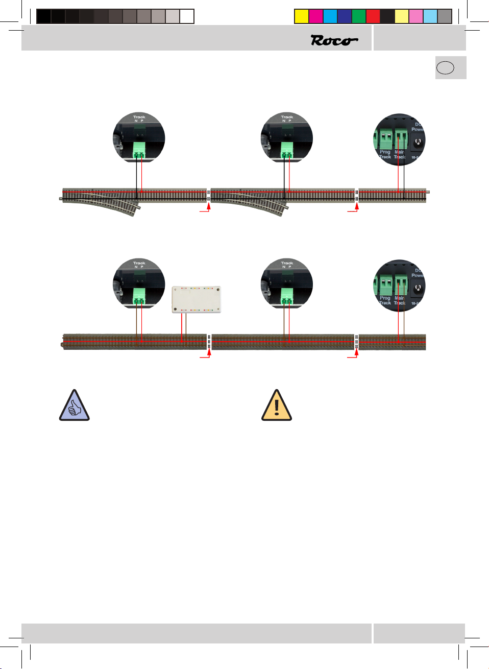
ACHTUNG: Bei angrenzenden
Booster-Abschnitten darf nur bei
einem der beiden Booster die Option
Auto-Invertierung aktiviert sein, da
sonst beide gleichzeitig umpolen
würden, was zu einem Kurzschluss
führt.
ACHTUNG: Wenn angrenzende
Booster-Abschnitte keine RailCom-
Lücke erzeugen, dann muss diese
Option deaktiviert werden (10761,
10764, 10768, 10830, 10832, 10762,
10765 können kein RailCom).
RailCom
Mit dieser Option kann die Erzeugung einer
RailCom-Lücke aktiviert/deaktiviert werden,
(standardmäßig aktiviert).
8010805920 V_2016.indd 9 15.04.2016 10:51:07

10
D
Technische Daten:
Eingangsspannung 12-24V DC (Nur Schaltnetzteile verwenden!)
Eingangsstrom 3,1A max.
Eigenverbrauch 0,6W
Ausgangsspannung Eingangsspannung – 1,1V
Ausgangsleistung 3A max.
Überlastschutz thermisch, Strom- und Netzteilspannungsmessung
Digitalsystem DCC und/oder Motorola
RailCom RailCom-Lücke ist deaktivierbar
Auto-Invertierung durch Strommessung, ist deaktivierbar
B-BUS Kurzschlussmeldung ist deaktivierbar
Dimensionen L x B x H 104mm x 104mm x 25mm
Lieferumfang:
•Z21-Booster
•B-BUS-Kabel
•Steckklemme für den Gleisanschluss
Dieses Symbol auf dem Produkt, der Verpackung oder in der
Dokumentation bedeutet, dass dieses Produkt nicht wie Hausmüll
behandelt werden darf. Stattdessen soll dieses Produkt zu dem
geeigneten Entsorgungspunkt zum Recyclen von Elektro-
und Elektronikgeräten gebracht werden. Wird
das Produkt korrekt entsorgt, helfen Sie mit,
negativen Umwelteinüssen und Gesundheitsschäden
vorzubeugen, die durch unsachgemäße Entsorgung
verursacht werden könnten. Das Recycling von Material wird unsere
Naturressourcen erhalten. Für nähere Informationen über das
Recyclen dieses Produktes kontaktieren Sie bitte Ihr lokales Bürgerbüro,
Ihren Hausmüll-Abholservice oder das Geschäft, in dem Sie
dieses Produkt gekauft haben.
RailCom ist eine eingetragene Marke von Lenz Elektronik GmbH
Motorola ist eine eingetragene Marke der Motorola Inc., Tempe-Phoenix/Arizona (USA)
8010805920 V_2016.indd 10 15.04.2016 10:51:07

11
GB
Important information:
• No guarantee will be provided for damage or malfunctions if you combine the Z21 booster with third-party
products.
• Under no circumstances may the Z21 booster be supplied with AC voltage.
• Ensure that each Z21 booster has its own power supply unit otherwise an impermissible short circuit to ground
can easily occur which could destroy your Z21 booster or other digital components!
• Do not use the Z21 booster if the mains plug, mains cable or the device itself if defective or damaged.
• Only perform connection work if the operating voltage is switched off.
• The warranty will become void if you open the Z21 booster housing.
• Work carefully and ensure that no short circuits occur when connecting to the track system. An incorrect
connection can destroy the digital components. Consult your specialist dealer if necessary.
• The Z21 booster may become warm when in operation. Ensure a sufficient distance between the booster and
neighbouring parts in order to ensure sufficient ventilation and cooling of the device.
• Never leave your model railway system running without supervision. An unnoticed short circuit can result in
heating and represents a risk of fire.
Thank you very much for choosing a Z21 booster
from Roco and Fleischmann.
Over the next few pages, we will explain everything you need to know in order to connect the
Z21 booster to your system and to commission it. This manual also contains plenty of practical
tips. Please read these instructions and warning information carefully prior to commissioning.
Although the Z21 booster is extremely robust, it can become permanently damaged if
connected or operated incorrectly.
8010805920 V_2016.indd 11 15.04.2016 10:51:07

12
GB
Quick Start Guide
Normal mode button:
• Press briefly:
Alternates between normal mode and STOP
•Hold until „Config“ flashes (min. 3 seconds):
Configuration mode
• Hold until all LEDs illuminate (min. 6 seconds):
Reset factory settings
Buttons in configuration mode:
•Press briefly:
Activate / deactivate selected option
• Hold until „Status“ illuminates
(min. 3 seconds):
Next option
Steady blue Normal mode
Flashes blue STOP / no B-BUS
Flashes red Short circuit
Flashes red 3x Excessive temperature
Steady green Track output inverted
Normal mode LED status
LED-Status Kongurationsmodus
Steady blue Input conrmation
Steady red Option deactivated
Steady green Option activated
Flashes 1x Option 1: RailCom gap
Flashes 2x Option 2: Auto inversion
Flashes 3x Option 3: Notication of
short circuit to the
control centre
Switching power
supply: 12-24 V
DC, minimum 3A
3A track output Roco DCC
booster-bus and/or
Motorola
The model railway system contains many power consumers that are connected to the digital voltage
such as locomotives, points, signals, lights, etc. These components need to be supplied with power. If the
system exceeds a certain size, the power from the track output of the control centre is no longer sufcient
and boosters then need to be used. These boosters then supply new track and control sections with up to
3A. If the RailCom option is activated (activated as standard), the booster generates a so-called RailCom
gap on DCC packages. This gap enables the use of RailCom local detectors or RailCom-capable track
occupancy sensors such as the 10808 Z21 detector. The Z21 booster has been specially customised for the
Z21 product line but is also compatible with older Roco control centres and boosters (RailCom may have
to be deactivated).
Intended use and function
8010805920 V_2016.indd 12 15.04.2016 10:51:07

13
GB
Booster assembly
Assemble the booster in a location that is
easy to view and has sufcient ventilation
in order to be able to dissipate the waste
heat. Do not position the booster close to
strong heat sources such as radiators or in
positions exposed to direct sunlight under
any circumstances. This booster has been
exclusively developed for dry indoor areas.
Therefore, do not operate the booster in
environments with high temperature and
humidity uctuations.
Tip: When assembling the booster, use
round head screws such as
3x30 mm screws.
Connecting the booster - B-BUS
Z21
The booster is connected to the control centre, e.g. Z21 on the „B-BUS“ or to another booster via the
enclosed four-pole B-BUS cable. The connection on older control centres or boosters may be labelled as
„Booster out“. In doing so, it is unimportant which of the two bushes are used on the booster. The booster
accepts both the DCC as well as the Motorola protocol.
Z21-Booster Z21-Booster
ATTENTION: The RailCom
function must be deactivated if
different mixed boosters are used
(please refer to the Conguration
Chapter for further information).
Information: If you do
not wish for the short
circuit notication to be
forwarded to the control
centre, this function can be
deactivated (please refer to
the Conguration Chapter for
further information).
Replacement booster cable, Art. no.: 10757
etc.
8010805920 V_2016.indd 13 15.04.2016 10:51:08

14
GB
Connecting the booster - Power supply unit
Only switching power supplies with DC voltage output may be used to
supply the booster with power. Under no circumstances may the Z21 booster
be supplied with AC voltage, e.g. with a conventional transformer.
Ensure that each Z21 booster has its own power supply unit otherwise an
impermissible short circuit to ground can easily occur which could destroy
your Z21 booster or other digital components!
Tip: We recom-
mend the Roco
switching power
supply 10851.
Switching power
supply: 12-24 V
DC, minimum out-
put current: 3A
Information: How to calculate the power consump-
tion of a H0 system:
• Stationary locomotives with light: Approx. 100 mA
• Moving locomotives (depending on size and load):
Between 300 and 600mA
• Illuminated carriages: Approx. 30 mA per bulb
(Attention: Signicant uctuations.)
• Digital coupling or smoke generator: Approx.
100mA
•Digital points drives or points decoder: Approx. 500
mA reserve
Connecting the booster - Track output
The rails are connected to the booster via the enclosed plug-in terminal. Use cable
cross-sections of between 0.5 mm2 and 1.5 mm2 for supply purposes. The best
option when dealing with longer track sections is to provide a supply approximately
every 2 metres.
ATTENTION: If the power
consumption constantly exceeds 2.5
A, the section is overloaded and must
be partitioned (an additional booster is
required). This ensures a small reserve
in order to be able to safely switch
points or similar devices.
Information: Ensure that the
connecting tracks do not contain
any condensers (often required in
analogue mode).
3A track output
8010805920 V_2016.indd 14 15.04.2016 10:51:08

15
GB
Connecting to two-line track
ATTENTION: It is possible for only the
middle conductors to be disconnected
and to keep the outer conductors
connected if this is necessary for system-
related reasons. However, this is not
recommended and is carried out at your
own risk. In doing so, it must also be
ensured that only Z21 boosters are used
on the system.
Information: In three-line mode, it is
important to pay attention to polarity as
functional impairments may otherwise
occur on older Motorola
decoders. Please use rocker pick-up shoes
at the separating points.
Anschluss am Dreileitergleise
Booster section 1 Booster section 1 Z21
Disconnect on
both sides
Booster section 1 Booster section 1 Z21
Disconnect all three lines
MM-Decoder
Disconnect on
both sides
Disconnect all three lines
8010805920 V_2016.indd 15 15.04.2016 10:51:09

16
GB
Connection as a terminal loop
Information: If the booster is
used as terminal loop module, „auto
inversion“ must be activated (please
refer to the Conguration Chapter for
further information).
Buttons and configuration
You can congure and operate the booster via the button. Activate / deactivate track
output:
If the booster is in normal mode (the blue LED is steady), the track output can be
switched off by briey pressing the button (the blue LED ashes). The track output is
re-activated by briey pressing the button once again.
Conguration:
In order to move into conguration mode, the button must be held for at least 3 seconds
until the white „Cong“ LED begins to ash (the track is deactivated in conguration
mode). In doing so, the „Cong“ LED displays the currently selected option.
Booster button
Flashes white once Option 1: RailCom
Flashes white twice Option 2: Auto inversion
Flashes white 3 times Option 3: Notication of short circuit to the control centre
The selected option can be activated or deactivated by briey pressing the button.
This is signalled via a green LED for „activated“ or a red LED for „deactivated“.
8010805920 V_2016.indd 16 15.04.2016 10:51:09

17
GB
By pressing the button once again for at least 3 seconds, the setting is assumed and the device moves to
the next option. This is signalled by the illumination of the blue LED. Once the nal option has been assu-
med, the device leaves the conguration mode and all settings are saved. The track output is automatical-
ly re-activated after 3 seconds.
Reset to factory settings:
If it is necessary to reset all settings to the factory settings, simply press the button for longer than 6
seconds until all LEDs illuminate and the blue LED ashes. This triggers the reset. The track output is once
again automatically activated after 3 seconds.
Congurationoption:
Short circuit notication
The notication of short circuits to the control
centre is not performed when this option is
deactivated. However, this booster switches off
in the event of short circuits and automatically
attempts to re-activate the track output every 3
seconds (activated as standard).
Auto inversion
This option activates auto inversion which causes
an automatic polarity reversal of the track signal
if the booster is used as a terminal loop module
for example. However, it is also practical to not
always have to pay attention to the track polarity
(activated as standard).
ATTENTION: In terms of
neighbouring booster sections, only
one of the two boosters may have an
active auto inversion as both units
would otherwise reverse the polarity
simultaneously which would lead to a
short circuit.
ATTENTION: This option must be
deactivated if neighbouring booster
sections do not generate a RailCom
gap (10761, 10764, 10768, 10830,
10832, 10762, 10765 are unable to
work with RailCom).
RailCom
This option can activate/deactivate the RailCom
gap (activated as standard).
8010805920 V_2016.indd 17 15.04.2016 10:51:09

18
D
Technical Data:
Input voltage 12-24V DC (only use switching power supplies!)
Input current 3.1A max.
Own consumption 0.6W
Output voltage input current – 1.1V
Output power 3A max.
Overload protection thermal, current and power supply unit voltage
measuring
Digital system DCC and/or Motorola
RailCom RailCom gap can be deactivated
Auto-inversion by measuring the current, can be deactivated
B-BUS short-circuit message can be deactivated
Dimensions L x W x H: 104mm x 104mm x 25mm
Scope of delivery:
•Z21 booster
•B-BUS cable
• Plug-in terminal for the railway sidings
This symbol on the product, packaging or in the documentation
means that this product cannot be treated as domestic waste.
Instead, this product must be brought to a suitable disposal point
for the recycling of electrical and electronic devices. By correctly
disposing of this product, you are making a contribution to
preventing negative environmental impacts and hazards to health
which may be created by disposing of this product incorrectly.
Recycling materials assists in preserving our natural resources. For further
information concerning the recycling of this product, please contact your local
public ofce, your domestic waste collection service or the shop in which you
purchased this product.
RailCom is a registered trademark of Lenz Elektronik GmbH
Motorola is a registered trademark of Motorola Inc., Tempe-Phoenix/Arizona (USA)
8010805920 V_2016.indd 18 15.04.2016 10:51:09

19
F
Remarques importantes :
• Si vous combinez le Booster pour centrale Z21 avec des produits d‘autres fabricants, les dommages ou les
dysfonctionnements ne sont pas couverts par la garantie.
• Le Booster pour centrale Z21 ne doit en aucun cas être alimenté en courant alternatif.
• Utilisez un bloc d‘alimentation par Booster pour centrale Z21, sinon il est fort possible qu‘un court-circuit à
la masse accidentel se produise, ce qui peut détruire votre Booster pour centrale Z21 ou d‘autres composants
numériques !
• N‘utilisez pas le Booster pour centrale Z21 si la fiche de secteur, le câble de secteur ou l‘appareil est défectueux
ou endommagé.
• Procédez aux opérations de raccordement seulement lorsque la tension d‘alimentation est arrêtée.
• Le droit de garantie est annulé en cas d‘ouverture du boîtier du Booster pour centrale Z21.
• Travaillez prudemment et veillez à ce que tout risque éventuel de court-circuits soit exclu lors du raccordement
au système de voies ! Une erreur de raccordement peut causer la destruction des composants numériques. Faîtes
vous conseiller, le cas échéant, par votre revendeur spécialisé
• Pendant le fonctionnement du Booster pour centrale Z21, celui-ci peut s‘échauffer. Veillez à laisser suffisamment
d‘espace entre les pièces adjacentes, pour garantir une aération et un refroidissement suffisants de l‘appareil.
• Ne laissez jamais fonctionner votre réseau ferroviaire miniature sans surveillance ! Si un court-circuit se produit
de façon inaperçue, il existe un risque d‘incendie par échauffement !
Nous vous remercions d‘avoir choisi le Booster pour
centrale Z21 Roco et Fleischmann !
Dans les pages suivantes, nous vous dévoilons tout ce que vous devez savoir pour brancher
le booster pour centrale Z21 à votre installation et le mettre en service. Dans ce manuel,
vous trouverez également de nombreux conseils pratiques. Avant la mise en service, veuillez
lire attentivement ce manuel d‘utilisation ainsi que les avertissements. Bien que le Booster
pour centrale Z21 soit de construction solide, un raccordement mal effectué ou une mauvaise
manipulation peut entraîner des dommages permanents à l‘appareil.
8010805920 V_2016.indd 19 15.04.2016 10:51:09

20
F
Notice abrégée
Touches en fonctionnement normal :
• Appuyer brièvement :
alterner les fonctions de mode normal et d‘ARRET
•Maintenir jusqu‘à ce que „Config“ clignote (min. 3 s):
Mode configuration
• Maintenir jusqu‘à ce que toutes les LED
s‘allument (min. 6 s):
réinitialiser état d‘usine
Touches en mode configuration :
•Appuyer brièvement :
Activer/désactiver l‘option sélectionnée
• Maintenir jusqu‘à ce que „Etat“
s‘allume (min. 3 s):
Option suivante
s‘allume en bleu Mode normal
clignote en bleu ARRET / aucun B-BUS
clignote en rouge Court-circuit
clignote 3 fois en rouge Temp. excessive
s‘allume en vert Sortie de voie inversée
Etat LED mode normal
Etat LED mode conguration
s‘allume en bleu Conrmation de saisie
s‘allume en rouge Opt. désactivée
s‘allume en vert Opt. désactivée
clignote 1 fois Opt. 1: interv. RailCom
clignote 2 fois Opt. 2: auto-inversion
clignote 3 fois Opt.3: message¬
court-circuit à la centra-
le
Alimentation
à découpage :
12 -24 V DC au
minimum 3A
Sortie de voie 3A Roco Booster-Bus
DCC et/ou Mo-
torola
Sur un réseau ferroviaire miniature se trouvent de nombreux consommateurs qui sont raccordés à la
tension numérique comme les locomotives, les aiguillages, les signaux, les éclairages, etc. Ces composants
doivent être alimentés en énergie. Lorsque l‘installation atteint une certaine dimension, la puissance
de la sortie de voie de la centrale ne suft plus, il faut donc utiliser des amplicateurs, également
appelés „Boosters“. Ils fourniront de l‘énergie supplémentaire aux nouvelles sections de voie et de
commande jusqu‘à 3A. Lorsque l‘option RailCom est activée (activée par défaut), le Booster génère
pour les paquets DCC un intervalle RailCom, qui permet l‘utilisation de détecteurs locaux RailCom ou de
détecteurs d‘occupation de voie compatibles avec RailCom, comme par exemple le détecteur pour Z21
10808. Le Booster pour centrale Z21 a été spécialement conçu pour la gamme de produits Z21, mais il
est compatible avec les anciennes centrales et amplicateurs Roco (le cas échéant, le RailCom doit être
désactivé).
Usage prévu et fonctionnement
8010805920 V_2016.indd 20 15.04.2016 10:51:09
Table of contents
Languages:
Other roco Toy manuals
Popular Toy manuals by other brands

Rollplay
Rollplay 7221AC Owner's manual and assembly instructions

Hasbro
Hasbro G.I. Joe Ice Sabre with Frostbite figure instructions

marklin
marklin 29184 instruction manual

Mikado
Mikado LOGO 200 manual

Eduard
Eduard M-106A1 Armoured S.P. Mortar interior quick start guide

PACIFIC CYCLE
PACIFIC CYCLE KID TRAX RIDEAMALS JOSIE owner's manual

SPECIAL HOBBY
SPECIAL HOBBY SH48117 CAC-13 Boomerang Instruction

Mega Bloks
Mega Bloks MARVEL SPIDER-MAN 3 Sandman Bank Heist 2004 instruction manual

Redmon
Redmon Fun&FitnessKids Happy Bike owner's manual

Pilot RC
Pilot RC Yak 54 Assembly manual

Reely Sky
Reely Sky Fire Flame II operating instructions

Viessmann
Viessmann 5085 Operation manual