6) Remove the vibration sensor from its protective
packaging. Remove the liner from the adhesive
backing. Avoid touching the tape. Align the
sensor as shown in figures 1 and 2. Apply the
vibration sensor to the prepared area of the
feeder. Press the sensor very firmly onto the
feeder surface for at least 10 seconds.
7) Allow the vibration sensor at least 20 minutes to
cure before operation. Note it takes 72 hours for
the adhesive to fully cure at 70°F.
Alternatively, #8 or M4 screws can be used to mount
the sensor to the feeder. The hole centers are 1.375”
(3.49cm) apart.
D. ROUTE THE SENSOR CABLE to protect it from
strain due to vibration. The cable that attaches to the
sensor will not break from normal vibration; however,
some care should be used when routing the sensor
cable from the sensor to the control. The cable
should hang straight down from the sensor without
touching the feeder bowl or anything else. Then, the
sensor cable should curve towards the power control
with a bend radius larger than 3 inches (8cm).
Use a cable tie and an adhesive-backed mount to
attach the sensor cable to the side of the drive base.
See Figure 2. Clean the mounting area before
applying the adhesive-backed mount.
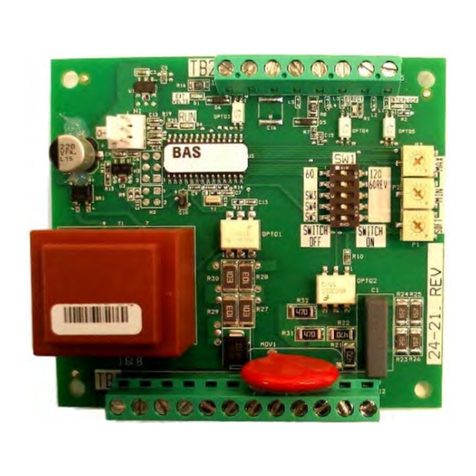
E. CONNECT THE SENSOR to the control. The
sensor’s brown wire connects to +12VDC at TB2-9.
The blue wire connects to the signal input at TB2-12.
14. SETTING CFR GAIN SELECTION
The CFR response rate can be increased with “High
Gain”. If the response is too quick, oscillating or
unstable, use “Low Gain”. See the S1 switch
selections for the “High” and “Low” CFR Gains.
15. OUTPUT CONNECTIONS
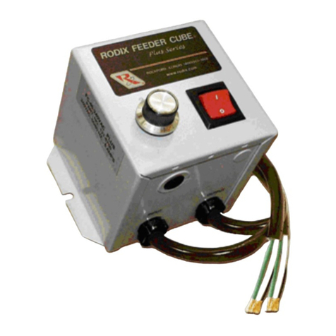
The 120V models in general purpose enclosures
provide a standard North American receptacle
(NEMA 5-15R) for connection to the feeder. 240V
models have a pigtail output cord. Power cords are
optional on Oil Resistant models.
16. SUPPLEMENTARY FEATURES
Special supplementary software features can be
enabled on the 24-490/24-491 circuit boards.
Included features: Constant On, High/Low Track level
control, 60 pulse polarity reversal, low pulse rate,
linear pot taper, Constant Feed Rate response time,
bowl out of parts, and two speed pots. See the S1
Switch Programming Chart. For more feature
information download (or request from RODIX) the
FC-90
Plus Series
Advanced Application Note.
17. STATUS LEDs
When the Sensor input is active, either the PNP or
NPN LED will be ON. When the RUN input circuit is
complete, the RUN LED will be ON. The AUX LED is
ON whenever the Aux output is turned ON.
TROUBLESHOOTING
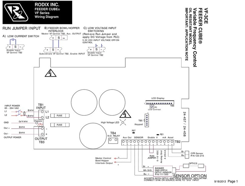
For the control to run: The RUN LED must be lit (see
Run Jumper Input chart on wiring diagram). The Main
Control Dial or 4-20mA signal must be present. Turn
the ON and OFF delay pots down CCW. The DIP
switch S1 must be set to match the sensor’s output
type, PNP or NPN. The PNP or NPN LED must light
up and turn off when making and breaking the 3- wire
DC parts sensor. If no parts sensor is connected, set
theS1INV/NORMswitchto“Invert”. Ifthefeederonly
hums, toggle the 60/120 dip switch.
For more troubleshooting helps, download the FC-90
Plus
Troubleshooting Guide at rodix.com
WARNING:
Fuses should be replaced with Bussman ABC or
Littelfuse 3AB "Fast Acting" type or equivalent of
manufacturer's original value.
Mounting this control on a vibrating surface will
void the warranty.
WARRANTY
Rodix Control Products are Warranted to be free from
defects in material and workmanship under normal use
for a period of two years from date of shipment. For the
full description of the warranty, terms, and software license,
please contact the factory.
For assistance installing or operating your Rodix Feeder
Cube® please call the factory or visit our web site.
Technical help is available to answer your questions and
email any needed information. To return a control for IN or
OUT of warranty service, please ship it prepaid to:
Rodix Inc., ATTN: Repair Department
If under warranty, Rodix will repair or replace your control
at no charge; If out of warranty, we will repair it and you will
be billed for the repair charges (Time and Material) plus the
return freight. Quotes for repairs are available upon
request. A brief note describing the symptoms helps our
technicians address the issue.
Feeder Cube® is a registered TM of Rodix Inc.
Banneris a registered Trademark of Banner Engineering Corp,
9714 10th Ave, Minneapolis, MN 55441
RODIX, INC.
2316 23rd Ave., Rockford, IL 61104
Toll Free (800) 562-1868, FAX (815) 316-4701
rodix.com
FC-90 Plus Set Up J.docx 2/21/2018 Page 5
S1 Pro
rammin
Chart
Pro
ram Description S1 Sw. Positions
Switch 6 7 8 9 10
Standard Pro
ram 0 0 0 0 0
Constant ON 0 0 0 0 1
Hi
h/Low Track 0 0 0 1 0
Linear Pot Taper 0 0 0 1 1
0-20m
00100
2-Speed Operation 0 0 1 0 1
Bowl Out Parts, Stop 0 0 1 1 0
BOP stop/ with alarm 0 0 1 1 1
BOP alarm w/o stop 0 1 0 0 0
30/15 hertz operation 0 1 0 0 1
ux Invert 0 1 0 1 0
ir Jet Timers 0 1 0 1 1
40 Pulse operation 0 1 1 0 0
Low Amplitude at “1” 0 1 1 0 1
Low CFR Gain 0 1 1 1 0
Hi
h CFR Gain 0 1 1 1 1
Waveform Reversal 1 0 0 0 0
Constant ON, WR 1 0 0 0 1
Hi
h/Low Track, WR 1 0 0 1 0
Linear Pot Taper, WR 1 0 0 1 1
0-20mA, WR 1 0 1 0 0
Option Pro
. 1 0 1 0 1
Option Pro
. 1 0 1 1 0
Option Pro
. 1 0 1 1 1
+
TB2
12 9
-
Brown
CFR SENSOR
123-170
11
Blue
10
