Table of Contents
1. Introduction...................................................................................................................................... 1-1
Overview...........................................................................................................................................1-2
Package Checklist...............................................................................................................................1-2
Product Features ................................................................................................................................1-2
EOM-G103-PHR-PTP Hardware Specifications .........................................................................................1-3
EOM-G103-PHR-PTP Hardware Block Diagram........................................................................................1-4
Appearance........................................................................................................................................1-4
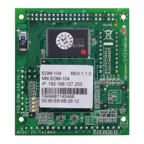
EOM-G103-PHR-PTP Embedded Module..........................................................................................1-4
EOM-G103-PHR-PTP Evaluation Board............................................................................................1-5
Dimensions (unit: mm)................................................................................................................1-5
2. EOM-G103-PHR-PTP Functionality..................................................................................................... 2-1
EOM-G103-PHR-PTP Embedded Module Functions...................................................................................2-2
LAN Ports ...................................................................................................................................2-2
Console Port...............................................................................................................................2-2
GPIO .........................................................................................................................................2-2
Pin Assignments.................................................................................................................................2-2
Pin assignment table for JP1 (2 x 40).............................................................................................2-3
Pin assignment table for JP2 (2 x 10).............................................................................................2-3
3. EOM-G103-PHR-PTP-ST Functionality ............................................................................................... 3-1
EOM-G103-PHR-PTP-ST Development Board ..........................................................................................3-2
Combining the EOM-G103-PHR-PTP-ST with the Embedded Module...........................................................3-2
LED Indicators....................................................................................................................................3-3
Wiring Requirements...........................................................................................................................3-4
Connecting the Power .........................................................................................................................3-4
LAN Ports and Pin Assignments ............................................................................................................3-4
Reset Button......................................................................................................................................3-5
4. PCB Layout and Design Guidelines .................................................................................................... 4-1
General Rules.....................................................................................................................................4-2
Power Ground Rules............................................................................................................................4-2
Chassis Ground ..................................................................................................................................4-2
Magnetic Noise Zone...........................................................................................................................4-3
Differential Signal Layout.....................................................................................................................4-3
USB Signal Layout ..............................................................................................................................4-3
Heat Sink Requiremenrs ......................................................................................................................4-3
Design Guidelines...............................................................................................................................4-4
