Rohde & Schwarz R&S RT-ZM15 User manual

R&S®RT‑ZM
Modular Probe System
User Manual
User Manual
Version 04
1419312802
(>COL2)

This manual describes the following R&S®RT-ZM models:
●R&S®RT-ZM15 (1800.4700K02)
●R&S®RT-ZM30 (1419.3005K02)
●R&S®RT-ZM60 (1419.3105K02)
●R&S®RT-ZM90 (1419.3205K02)
●R&S®RT-ZM130 (1800.4500K02)
●R&S®RT-ZM160 (1800.4600K02)
© 2019 Rohde & Schwarz GmbH & Co. KG
Mühldorfstr. 15, 81671 München, Germany
Phone: +49 89 41 29 - 0
Fax: +49 89 41 29 12 164
Email: [email protected]
Internet: www.rohde-schwarz.com
Subject to change – Data without tolerance limits is not binding.
R&S® is a registered trademark of Rohde & Schwarz GmbH & Co. KG.
Trade names are trademarks of the owners.
1419.3128.02 | Version 04 | R&S®RT‑ZM
Throughout this manual, products from Rohde & Schwarz are indicated without the ® symbol and without
product type numbers, e.g. R&S®RT-ZM15/30/60/90/130/160 is indicated as R&S RT-ZM.

Contents
R&S®RT‑ZM
3User Manual 1419.3128.02 ─ 04
Contents
1 Product Description.............................................................. 5
1.1 Key Features and Key Characteristics............................................... 5
1.1.1 Key Characteristics................................................................................. 5
1.1.2 Key Features...........................................................................................6
1.2 Unpacking..............................................................................................7
1.2.1 Inspecting the Contents.......................................................................... 7
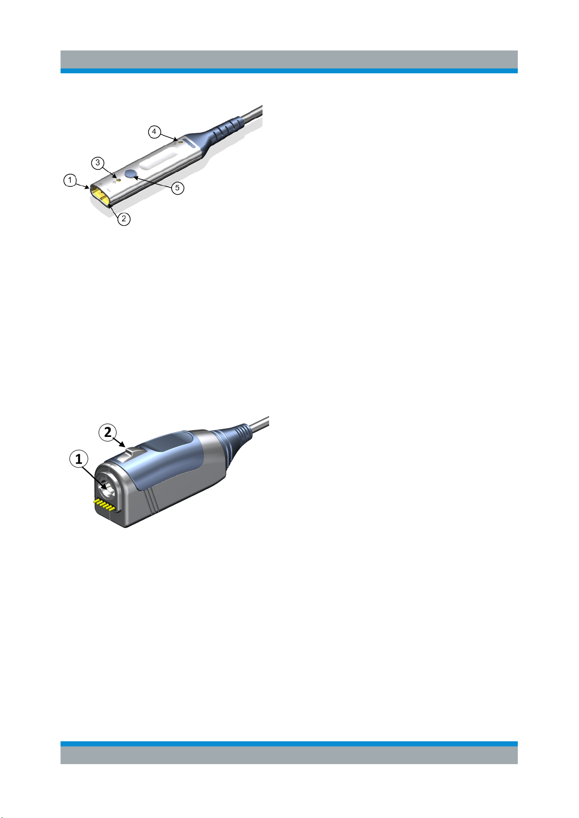
1.3 Description of the Probe...................................................................... 8
1.3.1 Probe Amplifier....................................................................................... 8
1.3.2 Probe Box............................................................................................... 9
1.3.3 Probe Tip Modules.................................................................................. 9
1.3.4 Accessories and Items..........................................................................10
2 Putting into Operation.........................................................13
2.1 Connecting the Probe to the Oscilloscope...................................... 14
2.2 Identification of the Probe..................................................................15
2.3 MultiMode............................................................................................ 15
2.4 Dynamic Range and Operating Voltage Window............................. 17
2.5 Micro Button........................................................................................18
2.6 Offset Compensation..........................................................................18
2.6.1 Differential Offset.................................................................................. 20
2.6.2 Common Mode Offset...........................................................................20
2.6.3 Positive Input Single-Ended Offset....................................................... 21
2.6.4 Negative Input Single-Ended Offset......................................................22
2.7 R&S ProbeMeter..................................................................................23
3 Connecting the Probe to the DUT...................................... 24
3.1 R&S RT-ZMA10 Tip Cable Solder-In.................................................. 25

Contents
R&S®RT‑ZM
4User Manual 1419.3128.02 ─ 04
3.2 R&S RT-ZMA12 Tip Cable Square Pin...............................................27
3.3 R&S RT-ZMA14 Tip Cable Flex Connect........................................... 28
3.4 R&S RT-ZMA15 Tip Cable Quick Connect........................................ 29
3.5 R&S RT-ZMA30 Browser Module.......................................................30
3.6 R&S RT-ZMA40 SMA Module............................................................. 32
3.7 R&S RT-ZMA50 Extreme Temperature Kit........................................ 33
4 Maintenance and Service....................................................35
4.1 Cleaning...............................................................................................35
4.2 Contacting Customer Support...........................................................35
4.3 Returning for Servicing...................................................................... 36
4.4 Calibration Interval............................................................................. 37
4.5 Spare Parts ......................................................................................... 37

Product Description
R&S®RT‑ZM
5User Manual 1419.3128.02 ─ 04
1 Product Description
1.1 Key Features and Key Characteristics
The R&S RT-ZM is a modular probe consisting of a probe amplifier and various
probe tip modules for different applications.
The R&S RT-ZM probe family features the MultiMode function which allows you
to switch between single-ended, differential and common mode measurements
without reconnecting or re-soldering the probe.
With different tip modules and tip cables, the R&S RT-ZM probe can be connec-
ted to a wide variety of devices under test (DUT) and is suitable for various mea-
surement tasks.
Provided with special features such as the R&S ProbeMeter and the micro button,
the R&S RT-ZM is designed to meet tomorrow's challenges in probing.
The probe is equipped with theRohde & Schwarz probe interface. It can be con-
nected to any Rohde & Schwarz instrument that is compatible with this interface.
When connected to the front panel, the probe is controlled by the oscilloscope's
software. Supported oscilloscopes are listed in the data sheet.
1.1.1 Key Characteristics
The key characteristics of the probe are the following:
MultiMode feature for differential, common mode and single-ended measurements
Two different probe gain settings with 10:1 and 2:1 attenuation to achieve low system noise
Bandwidth DC to 1.5 GHz (R&S RT-ZM15)
DC to 3 GHz (R&S RT-ZM30)
DC to 6 GHz (R&S RT-ZM60)
DC to 9 GHz (R&S RT-ZM90)
DC to 13 GHz (R&S RT-ZM130)
DC to 16 GHz (R&S RT-ZM160)
Dynamic range ±2.5 V (10:1 attenuation)
±0.5 V (2:1 attenuation)
Key Features and Key Characteristics

Product Description
R&S®RT‑ZM
6User Manual 1419.3128.02 ─ 04
Operating voltage window
(each pin to GND)
±7.0 V with ±16 V offset capability, DC to 100 kHz
±5.0 V with ±16 V offset capability, > 100 kHz
Maximum non-destructive input voltage ±30 V
Input resistance Differential: 400 kΩ
Single-ended: 200 kΩ
R&S ProbeMeter, measurement error <0.2 %
R&S ProbeMeter, dynamic range ±7 V
Offset capability ±16 V for compensating single-ended, differential and
common mode DC offsets
Low zero and gain errors throughout the entire temperature range for all measurement modes
Micro button
Rohde & Schwarz probe interface
1.1.2 Key Features
Micro button
The micro button at the probe head can remotely control different functions on the
base unit. The assigned function is configured via the base unit.
For details, see Chapter 2.5, "Micro Button", on page 18.
R&S ProbeMeter
The R&S ProbeMeter measures the DC voltage of the input signal directly at the
probe tip. It provides a continuous high-precision DC voltage measurement that is
independent of the settings of the oscilloscope and runs in parallel to the time
domain measurement. If activated on the base unit, the measured value is dis-
played on the screen of the Rohde & Schwarz oscilloscope.
The R&S ProbeMeter simultaneously measures both differential and common
mode DC voltages.
For details, see Chapter 2.7, "R&S ProbeMeter", on page 23.
Probe DC correction
The probe amplifier includes an integrated data memory with individually deter-
mined DC correction parameters (e.g. gain, offset). These correction parameters
are read out and processed by the Rohde & Schwarz oscilloscope. As a result,
Key Features and Key Characteristics

Product Description
R&S®RT‑ZM
7User Manual 1419.3128.02 ─ 04
the probe offers a very high degree of DC accuracy so that additional calibration
procedures are not required.
Probe frequency correction
The R&S RT-ZM probe amplifier includes an integrated data memory with individ-
ually measured S-parameters. These correction parameters are read out and pro-
cessed by the Rohde & Schwarz oscilloscope. This leads to a more accurate
probe frequency response and an enhanced measurement accuracy.
1.2 Unpacking
The carrying case contains the following items:
●R&S RT-ZM modular probe
●Carrying case
●Accessory boxes
●User manual
●R&S RT-ZM data sheet
●Calibration certificate
●Documentation of calibration values (if
ordered)
●Foam inlay for tip cables
If R&S RT-ZMA tip modules were ordered, they come in a separate packaging
and can be inserted into the foam inlay.
1.2.1 Inspecting the Contents
●Inspect the package for damage.
Keep the package and the cushioning material until the contents have been
checked for completeness and the device has been tested.
If the packaging material shows any signs of stress, notify the carrier and your
Rohde & Schwarz service center. Keep the package and cushioning material
for inspection.
●Inspect the probe.
Unpacking

Product Description
R&S®RT‑ZM
8User Manual 1419.3128.02 ─ 04
If there is any damage or defect, or if the R&S RT-ZM modular probe does not
operate properly, notify your Rohde & Schwarz service center.
●Inspect the accessories.
If the contents are incomplete or damaged, notify your Rohde & Schwarz ser-
vice center.
1.3 Description of the Probe
The probe consists of the active probe amplifier, the probe box for connection to
the oscilloscope, the probe cable and various probe tip modules.
Figure 1-1: R&S
RT-ZM probe consisting of probe amplifier and probe box
1.3.1 Probe Amplifier
The probe amplifier is designed for easy handling and high performance mea-
surements. The R&S RT-ZM probe amplifier is designed for use with the R&S RT-
ZMA probe tip modules.
See also: Chapter 3, "Connecting the Probe to the DUT", on page 24.
Description of the Probe

Product Description
R&S®RT‑ZM
9User Manual 1419.3128.02 ─ 04
(1) Positive coaxial input
(2) Negative coaxial input
(3) Ground socket
(4) Termination voltage socket
(5) Micro button
Signal and Termination voltage sockets are
compatible with 0.64 mm (25 mil) square pins
and 0.6 mm to 0.8 mm (24 mil to 35mil) round
pins.
1.3.2 Probe Box
The probe box connects the probe and the oscilloscope via the Rohde & Schwarz
probe interface. The Rohde & Schwarz probe interface contains a male precision
7 mm (276 mil) BNC connector and six pogo pin connectors. This interface pro-
vides the required supply voltage and is also used to transmit analog signals and
digital data simultaneously. All the analog voltages required by the probe are gen-
erated in the probe box. This approach ensures that it will be possible to operate
future probes on any base unit that features a Rohde & Schwarz probe interface.
(1) Rohde & Schwarz probe interface with
7 mm (276 mil) coaxial connector and 6 pogo
pins
(2) Release knob
1.3.3 Probe Tip Modules
To use the probe for measurements, select the appropriate probe tip module and
connect it to the probe amplifier.
Figure 1-2 shows all probe tip modules are available for the R&S RT-ZM probe.
The usage of probe tip modules is described in Chapter 3, "Connecting the Probe
to the DUT", on page 24.
If you need more probe tip modules, you can order them at Rohde & Schwarz.
The order numbers are provided in the data sheet.
Description of the Probe

Product Description
R&S®RT‑ZM
10User Manual 1419.3128.02 ─ 04
Figure 1-2: R&S
RT-ZM probing system compatibility chart
1.3.4 Accessories and Items
1.3.4.1 Accessories Supplied
Table 1-1 shows the accessories that are supplied with the R&S RT-ZM modular
probe.
Table 1-1: Accessories supplied
Item Quantity Description
1 Lead, 15 cm / 5.9 in
1 Solder wire 0.1mm, Ag plated, 10 m
Description of the Probe

Product Description
R&S®RT‑ZM
11User Manual 1419.3128.02 ─ 04
Item Quantity Description
1 Solder wire 0.2mm, Ag plated, 10 m
1 Solder wire, lead free, 5 m
7 Adhesive pads
20 Solder in resistor (270 Ω) for R&S RT-ZMA15
20 Solder lead for R&S RT-ZMA12/15
For a list of spare parts, see Chapter 4.5, "Spare Parts ", on page 37.
1.3.4.2 Optional Accessories
If the delivered accessories do not meet individual customer requirements,
Rohde & Schwarz offers different accessory sets for sale. The order numbers are
provided in the data sheet.
Table 1-2: Optional accessories
Accessory set Items Quantity
R&S RT-ZA4 mini clips Mini clip 10
R&S RT-ZA5 micro clips Micro clip 4
Description of the Probe

Product Description
R&S®RT‑ZM
12User Manual 1419.3128.02 ─ 04
Accessory set Items Quantity
R&S RT-ZA6 lead set Lead, 6 cm / 2.4 in
Lead, 15 cm / 5.9 in
5
5
R&S RT-ZA9 probe box to
N/USB adapter
The adapter connects the R&S RT-ZM modular
probe to any other oscilloscope or any other
measurement instrument (e.g. a network or
spectrum analyzer).
Using the USB interface of the adapter, the
probe can be powered and controlled from any
conventional PC. However, full software func-
tionality is only provided by the supported oscil-
loscopes (see data sheet).
1
1.3.4.3 Service Accessories
To order accessories for servicing the probe, contact your Rohde & Schwarz ser-
vice center. The following accessories are available:
Table 1-3: Service accessories
Item Description
R&S RT-ZK3 The service kit is used to calibrate the probe, to do perform-
ance tests, and for servicing. The service kit includes all
adapters and accessories to connect the probe to the
required measuring instruments.
R&S RT-ZM Service Manual The service manual contains a detailed description of the
performance test to verify the specifications, and other
important service procedures.
Description of the Probe

Putting into Operation
R&S®RT‑ZM
13User Manual 1419.3128.02 ─ 04
2 Putting into Operation
The probe is designed for usage with oscilloscopes that have a Rohde & Schwarz
probe interface. Supported Rohde & Schwarz oscilloscopes are listed in the pro-
be's data sheet.
Read and observe the printed "Basic Safety Instructions" that are delivered with
the probe. Also, read and observe the safety instructions of the oscilloscope the
probe is connected to.
Maximum non-destructive input voltage
The maximum non-destructive input voltage is ±30 V. A higher input voltage
can destroy the probe.
Risk of device damage
The R&S RT-ZM can withstand a moderate amount of physical and electri-
cal stress. To avoid damage, treat the probe with care:
●Do not exceed the specified voltage limits.
●Connect the R&S RT-ZM only to an instrument with Rohde & Schwarz
probe interface. Never connect it to a usual BNC jack. Although the
7 mm coaxial connector looks like a standard BNC connector, it is con-
structed differently and does not fit to the standard BNC jack. The inter-
face of the R&S RT-ZM can withstand a higher frequency limit.
●Handle the probe by the probe tip module or probe box.
●Handle the probe by the probe head or probe box. Avoid excessive
strain on the probe cable, and kinking.
●Prevent the probe from receiving mechanical shock.
●Do not spill liquids on the probe.
●Store the probe in a shock-resistant case, e.g. in the foam-lined ship-
ping case.

Putting into Operation
R&S®RT‑ZM
14User Manual 1419.3128.02 ─ 04
During usage, the probe slightly heats up. Warming is normal behavior and not a
sign of malfunction.
2.1 Connecting the Probe to the Oscilloscope
1. If your DUT is floating and not grounded, connect the DUT ground to the oscil-
loscope ground before connecting any probe tip module to your DUT.
2. Connect the probe box (1) to the Rohde & Schwarz probe interface of the
oscilloscope (2).
The probe snaps in when connected properly to the port.
Figure 2-1: Connecting the probe to the Rohde
&
Schwarz oscilloscope
► To disconnect the probe:
a) Press and hold the release button (3).
b) Pull the probe box away from the oscilloscope.
Connecting the Probe to the Oscilloscope

Putting into Operation
R&S®RT‑ZM
15User Manual 1419.3128.02 ─ 04
2.2 Identification of the Probe
When the probe is connected to the oscilloscope, the oscilloscope recognizes the
probe and reads out the probe-specific parameters.
The complete probe information is shown in the probe settings dialog. For more
information, refer to the user manual of your oscilloscope.
2.3 MultiMode
The R&S RT-ZM probe family features the MultiMode function which allows you
to switch between single-ended, differential and common mode measurements
without reconnecting or resoldering the probe.
Four different input voltages can be measured with the MultiMode feature:
●P-Mode: (pos.) Single-ended input voltage (Vp)
Voltage between the positive input terminal and ground
●N-Mode: (neg.) Single-ended input voltage (Vn)
Voltage between the negative input terminal and ground
●DM-Mode: Differential mode input voltage (Vdm)
Voltage between the positive and negative input terminal
●CM-Mode: Common mode input voltage (Vcm)
Mean voltage between the positive and negative input terminal vs. ground
In the N-Mode, the signal at negative input terminal is not inverted.
MultiMode

Putting into Operation
R&S®RT‑ZM
16User Manual 1419.3128.02 ─ 04
Figure 2-2: Input voltage at probe tip
The R&S RT-ZM probes have three input terminals: the positive signal input (+),
the negative signal input (-), and ground.
Figure 2-3: Displayed voltage on oscilloscope screen
The setting of the probe mode is part of the probe settings of the channel to which
the probe is connected. You can also configure the micro button at the probe
amplifier to select the "Probe Mode". For more details, see the oscilloscope's user
manual.
The MultiMode feature is not supported by R&S RT-ZMA30 browser module
because there is no ground connection.
MultiMode

Putting into Operation
R&S®RT‑ZM
17User Manual 1419.3128.02 ─ 04
2.4 Dynamic Range and Operating Voltage Window
Two separate specifications are necessary to characterize the permissible input
voltage range of a R&S RT-ZM MultiMode probe.
Measurement mode Single-Ended P, Single-Ended N, or Common Mode
Dynamic Range ±2.50 V at 10:1 attenuation
±0.50 V at 2:1 attenuation
The dynamic range for single-ended (P-Mode, N-Mode) or common mode (CM-
Mode) measurements designates the maximum voltage (Vp, Vn) that can occur
between each of the two input terminals (Vp, Vn) and ground at the probe tip.
Differential measurement mode
Dynamic Range ±2.50 V at 10:1 attenuation
±0.50 V at 2:1 attenuation
Operating voltage window
(each pin to ground)
±7.0 VDC to 100 kHz
±5.0 V > 100 kHz at 10:1 attenuation
±1.0 V > 100 kHz at 2:1 attenuation
●The dynamic range for differential measurement (DM-Mode) designates the
maximum differential voltage Vdm that can occur between the positive and
negative signal terminal at the probe tip.
●At the same time, the two voltage values at each of the two signal terminals Vp
and Vn referenced to the common ground must not exceed a specific limit
value. This limitation is referred to as the operating voltage window (some
manufacturers also use the less precise term "common mode range" for the
same parameter).
●If one of these ranges is exceeded, an unwanted signal clipping can occur.
When measuring differential signals, frequently change to common mode
measurement to check for unallowed common mode signals.
●The attenuation is automatically selected by the oscilloscope's "V/div" setting
Dynamic Range and Operating Voltage Window

Putting into Operation
R&S®RT‑ZM
18User Manual 1419.3128.02 ─ 04
Figure 2-4: Operating voltage window for differential measurement mode DM at 10:1
attenuation for all offset settings at 0
V
2.5 Micro Button
The micro button provides easy and quick access to important functions of the
Rohde & Schwarz oscilloscope. After a function has been assigned, pressing the
micro button remotely controls this specific function on the base unit. For exam-
ple, "Run continuous" or "Run single" are often assigned to the micro button.
The configuration of the micro button is part of the probe settings of the channel
to which the probe is connected. For more details, see the oscilloscope's user
manual.
2.6 Offset Compensation
The R&S RT-ZM probe features the most comprehensive offset compensation
function. The compensation of DC components directly at the probe tip even in
front of the active probe amplifier is possible with an extremely wide compensa-
tion range of ±16 V.
The offset compensation feature is available for every MultiMode setting:
Offset Compensation

Putting into Operation
R&S®RT‑ZM
19User Manual 1419.3128.02 ─ 04
MultiMode
setting
Offset compensation Offset com-
pensation
range
Application
DM-Mode Differential DC voltage ±16 V Probing single-ended signals with the
R&S RT-ZMA30 browser module, e.g.
power rails with high DC component
and small AC signal.
CM-Mode Common mode DC
voltage
±16 V Measurements of signals with high
common mode levels, e.g. current mea-
surements with a shunt resistor.
P-Mode DC voltage at positive
input terminal
±24 V Measurement of single-ended AC sig-
nals with high superimposed DC com-
ponent at the positive input terminal.
Note: The maximum voltage difference
between the positive and negative input
terminals is 16 V.
N-Mode DC voltage at nega-
tive input terminal
±24 V Measurement of single ended AC sig-
nals with high superimposed DC com-
ponent at the negative input terminal.
Note: The maximum voltage difference
between the positive and negative input
terminals is 16 V.
You can set the offset compensation at the oscilloscope in various ways:
●Use the vertical [Position] knob. Before adjusting the offset, make sure that
the function of the knob is set to "Offset".
●Use the probe settings menu of the channel to which the probe is connected.
●Use the micro button to compensate the DC component of the measurement
signal, which is very helpful during measurements of input signals with differ-
ent DC offsets. Therefore, assign "Set offset to mean" to the micro button
function.
Setting an offset compensation voltage and then switching the probe measure-
ment mode does not affect the offset settings.
For example, you can measure a differential signal superimposed with a high DC
common mode component. First switch to CM-mode and compensate the com-
mon mode offset using the vertical [Position] knob until the measurement trace is
in the center of the oscilloscope screen. Then switch back to DM-mode to mea-
sure the differential signal.
For more details on setting the offset compensation voltage, refer to the user
manual of your Rohde & Schwarz oscilloscope.
Offset Compensation

Putting into Operation
R&S®RT‑ZM
20User Manual 1419.3128.02 ─ 04
2.6.1 Differential Offset
The differential offset function can compensate a DC voltage applied between the
positive (Vp) and the negative (Vn) input terminal at the probe tip. Setting a differ-
ential offset compensation in DM measurement mode is directly visible on the
oscilloscope screen as a voltage offset of the measured waveform.
Figure 2-5: Differential offset compensation for a single-ended measurement (negative
input connected to ground) using an R&S RT
‑
ZM15/30/60/90/130/160
2.6.2 Common Mode Offset
The common mode offset function can compensate a DC voltage applied to both
input terminals at the probe tip (referenced to ground). Setting a common mode
offset compensation in CM measurement mode is directly visible on the oscillo-
scope screen as a voltage offset of the measured waveform.
Offset Compensation
This manual suits for next models
5
Table of contents
Other Rohde & Schwarz Analytical Instrument manuals

Rohde & Schwarz
Rohde & Schwarz SMM-K507 User manual

Rohde & Schwarz
Rohde & Schwarz SMW-K40 User manual

Rohde & Schwarz
Rohde & Schwarz ZNH Series User manual

Rohde & Schwarz
Rohde & Schwarz DDF205 User manual

Rohde & Schwarz
Rohde & Schwarz UMS100 User guide

Rohde & Schwarz
Rohde & Schwarz Hameg HZO51 User manual
Popular Analytical Instrument manuals by other brands

CUES
CUES Solid FX instruction sheet

First Light
First Light C-RED One user manual

Underground Magnetics
Underground Magnetics Mag 6 manual

Gnom Rov
Gnom Rov GNOM PRO Operator's manual

STEPCRAFT
STEPCRAFT Touch-Probe Operating and safety instructions

Responsive Respiratory
Responsive Respiratory Respond O2 Operation manual