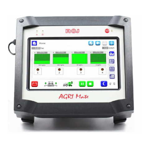
ROJ PCS 200 User manual

PCS 200
Installation
Operation
Maintenance
ORIGINAL INSTRUCTIONS

PCS 200
–
Rev. 3.0
–
October 2019
Copyright - ROJ - All rights reserved.
This manual is meant for the PCS 200 it users.
ROJ reserves the right to change at any time the contents of this manual, without notice.
For any technical or commercial problem, please contact your local ROJ dealer or call directly the ROJ customer
service center. We will be glad to meet your needs.
Thank you for your trust and we wish you all the best in your work.
The PCS 200 is a patented equipment which employs exclusive and high-tech solutions.

PCS 200
INSTALLATION, OPERATION AND
MAINTENANCE MANUAL
Edition: October 2019
Revision: 3.0
Direction and Plant: ROJ
ia ercellone 11
13900 Biella (BI)
Tel. +39 015 84 80 111
Fax +39 015 84 80 209
E-mail: [email protected]
www.roj.it


Table of contents
PCS 200 Kit
- i -
TABLE OF CONTENTS
PREFACE .......................................................................................................................................................................... iii
Safety ............................................................................................................................................................................ iv
CE Marking identification ............................................................................................................................................... iv
Compliance with the European irectives and Regulations…………………………………………………………………..v
Warranty and Responsibility of the Manufacturer .......................................................................................................... vi
Other Warranty terms .................................................................................................................................................... vi
1. GENERAL INFORMATION ......................................................................................................................................... 1.1
1.1 INTRO UCTION ............................................................................................................................................. 1.1
1.1.1 The ideal solution to control and optimize the seeding process ..................................................................... 1.1
1.1.2 Purposes of this manual ................................................................................................................................. 1.1
1.1.3 How to use this Manual ................................................................................................................................... 1.1
1.1.4 Symbols used in this Manual ........................................................................................................................... 1.2
1.1.5 Environment protection ................................................................................................................................... 1.2
1.2 GENERAL INFORMATION AN PERFORMANCES ..................................................................................... 1.3
1.2.1 Introduction ..................................................................................................................................................... 1.3
1.2.2 Functional blocks ............................................................................................................................................ 1.3
1.2.3 Machines on which the integration of the mentioned partly completed machinery is foreseen ....................... 1.4
1.2.4 Acronyms used ............................................................................................................................................... 1.4
1.3 COMPONENTS OF THE PCS 200 KIT .......................................................................................................... 1.5
1.4 GENERAL INFORMATION ABOUT SAFETY ................................................................................................. 1.7
1.4.1 esign criteria ................................................................................................................................................. 1.7
1.4.2 Safety evices and Solutions .......................................................................................................................... 1.8
1.4.3 Warning about residual risks ........................................................................................................................... 1.9
1.4.4 Warnings and Behaviour rules for the Operator .............................................................................................. 1.9
1.4.5 Noise levels ................................................................................................ 1.10
1.4.6 Proper and improper use ............................................................................................................................. 1.10
1.4.7 Reliability of the safety-related control systems ........................................................................................... 1.10
2. INSTALLATION ........................................................................................................................................................... 2.1
2.1 M 0 e M 2 (M ) GEARE MOTORS FEATURES .................................................................................. 2.1
2.2 MOTORS (M ) INSTALLATION
…..........................................................…………………………………………………
2.1
2.2.1 General principles ........................................................................................................................................... 2.1
2.3 M 0
………………………………………………………………………………...............……………………………………
. 2.1
2.3.1 Outlet shaft torque and speed ......................................................................................................................... 2.2
2.3.2 Outlet shaft dimensions ................................................................................................................................... 2.2
2.3.3 Fixing flange features ...................................................................................................................................... 2.2
2.2.2 Tilting limits ..................................................................................................................................................... 2.2
2.2.3 Transport cap .................................................................................................................................................. 2.3
2.2.4 Fastening ........................................................................................................................................................ 2.3
2.4 M 2
…………………………………………………………………………………………...............…………………………
..2.4
2.4.1 Outlet shaft torque, speed and axial/radial loads
………………………………………………........................………
...2.4
2.4.2 Overall dimensions of the geared motor and dimensions of the outlet shaft
………………………………….........
.2.4
2.4.3 Fixing flange features and geared motor fastening
……………..............................……………………………………
.2.5
2.5 ALTERNATOR ............................................................................................................................................... 2.6
2.5.1 Pulleys and rotation direction .......................................................................................................................... 2.6
2.5.2 Absorbed mechanical power and radial loads ................................................................................................. 2.7

Table of contents
- ii - PCS 200 Kit
2.6 BATTERY ........................................................................................................................................................ 2.8
2.7 SPEE SENSOR ............................................................................................................................................ 2.8
2.7.1 Single cogwheel sensor .................................................................................................................................. 2.8
2.7.2 Wheel sensor check ........................................................................................................................................ 2.9
2.8 MACHINE POSITION SENSOR ................................................................................................................... 2.10
2.8.1 Position sensor check ................................................................................................................................... 2.11
2.9 ECU POSITIONING ...................................................................................................................................... 2.11
2.10 S B POSITIONING…………………………………………………………………………………………………...2.12
2.11 WIRING IAGRAM……………………………………………………………………………………………………2.13
2.11.1 Main components……………………………………………………………………………………………………..2.14
2.11.2 ECU connection……………………………………………………………………………………………………….2.15
2.11.3 S B and power supply cables connection .................................................................................................... 2.16
2.11.4 M connection .............................................................................................................................................. 2.17
2.11.5 Safety switch ................................................................................................................................................. 2.20
3. USER MANUAL ........................................................................................................................................................... 3.1
3.1 MACHINE START-UP ..................................................................................................................................... 3.1
3.2 GRAPHIC ORGANIZATION ............................................................................................................................ 3.2
3.3 ACCESS LEVELS ........................................................................................................................................... 3.3
3.4 MOTORS A RESSING ................................................................................................................................ 3.4
3.4.1 Machine configuration ..................................................................................................................................... 3.5
3.4.2 Addressing ...................................................................................................................................................... 3.6
3.5 MACHINE CONFIGURATION ......................................................................................................................... 3.9
3.6 SEE ING SETTINGS .................................................................................................................................. 3.14
3.7 HOME ......................................................................................................................................................... 3.29
3.7.1 Rows exclusion ........................................................................................................................................... 3.31
3.7.2 Summary information about the seeding job……………………………………………………………………….3.32
3.7.3 Synoptic Tab ............................................................................................................................................... 3.33
3.7.4 Seeding job…………………………………………………………………………………………………………….3.37
3.8 ALARMS ..................................................................................................................................................... 3.38
3.9 SOFTWARE UP ATE AN PROTOCOL CHANGE .................................................................................. 3.45
3.10 STATISTICS ................................................................................................................................................. 3.52
3.11 TERMINAL .................................................................................................................................................... 3.57
3.12 TEST
……………………………………………………………………………………………………………………...............
.3.60
. MAINTENANCE AND TROUBLESHOOTING ............................................................................................................ .1
4.1 GENERAL INFORMATION ABOUT MAINTENANCE .................................................................................... 4.1
4.2 OR INARY PREVENTIVE MAINTENANCE TASKS TO BE CARRIE OUT BY THE OPERATOR…………4.1
4.3 MAINTENANCE/REPAIR TASKS RESTRICTE TO SPECIALIZE PERSONNEL ...................................... 4.2
4.4 SPARE PARTS ............................................................................................................................................... 4.3
4.5 PROCE URE FOR THE M REPLACEMENT OR EXCHANGE………………………………………………...4.5
UPDATES INDEX
9
/
18
/
2014
1
st
Edition
3
/
29
/
2016
2
nd
Edition
10
/
10
/
2019
3
rd
Edition

Preface
PCS 200 Kit - iii -
FOREWORD
All machines
(1)
and equipments designed and manufactured by ROJ are supplied
with the relative user
’
s manuals in compliance with the Essential Safety Requirement
(ESR) 1.7.4 - Instructions
–
Annex I of the Machinery irective 2006/42/EC.
Since the Machinery irective requirements, first of all the ESR in Annex I are
legally binding obligations, ROJ put a special emphasis on all ESR 1.7.4 clauses
during the drafting phase of these manual, in particular:
1. The ROJ user and maintenance manuals are supplied in the language of the
machine destination country, within the European Union and, when necessary,
an
“
Original language
”
copy of the manual is also provided.
2. The ROJ manuals always include a
“
proforma
”
copy of the EC eclaration of
Conformity or a
“
proforma
”
copy of the eclaration of Incorporation of the
“
Partly
completed machinery
”
for the relevant machine. These are just set out by way of
indication, and they shall not be considered as replacing the original eclaration
of Conformity Incorporation subscribed by the supplier, and delivered separately
to the Customer.
3. The ROJ Use and Maintenance manuals contain the information deemed as
important and necessary by the Manufacturer in order to:
Correctly understand the functioning principles of the machine.
Carry out all the handling/mounting, installation/power sources cabling, in
Sa e conditions, keeping into account the possible dangers related to the
above activities and giving directions, prescriptions and suggestions arising
from a careful risk assessment by the Manufacturer according to the
principles of the EN 12100:2010 Harmonized Standard and the ISO/TR
14121-2 Risk Assessment Guide.
Properly use the machine (safety devices, emergency devices, operating
procedures etc.) in Sa e conditions, drawing the operator
’
s attention on
the possible
“
Residual risks
”
, i.e. the still remaining risks despite all the
safety measures taken after the risk assessment, as previously mentioned.
Carry out the ordinary/preventive maintenance of the machine
(1)
in Sa e
conditions, also drawing the maintenance operators attention on the
possible Residual risks.
4. The ROJ Use and Maintenance Manuals do not only describe the intended use
of the machine
(1)
, but they also give information about the improper uses which
can reasonably be foreseen, based on the Manufacturer
’
s experience.

Preface
- iv - PCS 200 Kit
SAFETY
In relation to the risk analysis and assessment activities carried out in accordance
with the principles of the EN 12100: 2010 Harmonized Standard (as described in
par.3 above), ROJ has selected the various components of the control and safety
systems in a way as to ensure a reliability level suitable to the actual severity of the
hazard. To this purpose we have followed the requirements of the EN 13849-
1:2008/AC:2009 Harmonized Standard. Where the severity of the hazard is high (3
or 4 according to the classification of EN 12100:2010 Standard), the
countermeasures adopted are carefully evaluated in order to guarantee the
necessary safety margins, through redundancy or oversizing principles.
ROJ machines
(1)
comply with the Immunity and Electromagnetic Radiation Limits
defined by the EN ISO 14982: 2009 Harmonized Standard for Industrial
Environments. .
The ROJ User and Maintenance Manuals contain the updated list of the harmonized
standards applied during the design stage to guarantee the compliance with the
Essential Safety Requirement Listed on Annex I of 2006/42/EC irective, while the
design and implementation details are described on the Technical File kept by the
manufacturer according to the prescriptions of the Machinery irective 2006/42/EC.
(1) The term "Machine" as used in this manual generally refers to the definition given in the
Machine Directive, 2006 42 EC and therefore includes both the complete machinery
capable of performing a well-defined function and the "partly completed machinery", i.e.
driving systems or devices which cannot in themselves perform a specific function as
they are intended to be incorporated into a complete Machine.
CE Marking identi ication
The ROJ PCS xxx kits are CE marked on the back of the graphic display.

Preface
PCS 200 Kit - v -
Compliance with the European Directives and Regulations
Below is and extract of the Declaration o Incorporation, drawn up in accordance
with the requirements of Annex II B to 2006/42/EC irective, by which ROJ declares
that the following
“
partly completed machinery
”
:
Type: PCS 200 (PCS 100, PCS 150)
Footnote 1
Manufacturing year: See official Declaration of Incorporation
Serial number: See official Declaration of Incorporation
Target use: Servo power supply for seeders
cannot be commissioned unless the compliance of the machinery for agriculture on
which it has to be incorporated with the requirements of the 2006/42 /EC irective -
Annex II A - relating to the machine safety is ensured by the Manufacturer of the
agricultural machinery or the system integrator and that for its design and
manufacturing the principles and concepts introduced by the applicable paragraphs
of the following Harmonized Standards were adopted:
•EN ISO 12100:2010
•EN ISO13849-1:2008/AC:2009 • EN ISO13849-2:2012
•EN ISO 4254-1:2013 • EN 14018:2010
•EN ISO 14982: 2009
The equipment complies with the requirements of the 2014/30/EU irective
Note 2
relating to Electromagnetic Compatibility.
The person authorized to draw up the Technical ocumentation is:
Ing. Luca Bagatin (luca.bagati[email protected])
ROJ
complied with the following EHSRs (Essential health and safety requirements)
Annex 1 of the Machinery irective 2006/42/CE:
1.1.1
–
1.1.2
–
1.1.3
–
1.1.6
–
1.2.1
–
1.2.2
–
1.2.3
–
1.2.4
–
1.2.6
–
1.3.2
–
1.3.7
–
1.3.8
–
1.5.5
–
1.5.6
–
1.5.11
–
1.6.1
–
1.6.3
–
1.6.4
–
1.7.1
–
1.7.2
–
1.7.3
–
1.7.4
The compliance with applicable EHSRs not included in the above list, shall be
provided by the agricultural machine manufacturer or by the system integrator.
ROJ commits itself to send all relevant information about the PCS 200 partly
completed machinery via email or FTP, upon reasonable request made by the
relevant national authorities.
☞
The above indications are merely indicative and shall not be considered as
replacing the real Conformity Declaration signed and released by the
Manufacturer.
Note 1: The PCS 100 and PCS 150 kits are a subset of the PCS 200 kit
Note 2: The previous directive 2004 108 EC is repealed as from 04 20 2016

Preface
- vi - PCS 200 Kit
Warranty and Responsibility o the Manu acturer
The PCS 200 system described in this manual has been designed to be incorporated
into agricultural machinery (typically Seeders) and is therefore intended to operate
exclusively in combination with the above mentioned machines.
The various system components can be installed on the seeder by:
the seeder manufacturer
ROJ specialized and authorized personnel
The testing and commissioning of the system has to be performed in any case by
specialized personnel.
ROJ declines any responsibility in case of improper installation of the system not
following the instructions given in this manual or if the system is commissioned
without an authorization given by ROJ.
The end user must ensure that the equipment is used in accordance with the laws
and regulations in force in the country of installation, in particular as far as the
workers safety is concerned, and more generally in relation to the health, safety and
accident prevention requirements.
Any complaint must be promptly notified upon detection of any defect attributable to
the PCS 200 system components.
In the event that after an accurate assessment the complaint is deemed admissible,
ROJ may, at its sole discretion, replace or repair the defective components.
Other warranty terms
ROJ guarantees the quality and reliability of the equipment that has been designed
and manufactured to provide optimal performance.
The warranty does not cover any damages or indirect costs due to machine
downtime, or irregular operation caused by improper use of the equipment or of
single ROJ devices.
It is the responsibility of the end user to periodically perform cleaning and ordinary
preventive maintenance activities, aimed at keeping the equipment operation within
the expected performance range.
Any failure or improper equipment connection will void the warranty.
The warranty does not apply in case of floods, fire, electrostatic/inductive discharges
or in case of discharges caused by lightning or other phenomena external to the ROJ
equipment.
The warranty does not cover any damages to operators or other equipment/devices
connected to the ROJ equipment.
The customer is fully responsible for the proper use and maintenance of the
equipment, according to the instructions provided in this user manual.
This warranty does not cover parts subject to normal wear.
Any other orm o warranty is excluded.

General Information
PCS 200 Kit - 1.1 -
1 - GENERAL INFORMATION
1.1 INTRODUCTION
1.1.1 The ideal solution to control and o timize the seeding rocess
The PCS 200 kit has been designed for the installation on seeders in order to control
and optimize the entire seeding process.
Thanks to the excl sive flexibility and config rability the PCS 200 kit represents the
best sol tion for pne matic and precision seeders.
1.1.2 Pur oses of this manual
This man al aims to provide the PCS 200 Kit sers with the essential information on:
•
How to install and properly connect the system components safely.
•
How to config re the system and to set p the vario s operating parameters
according to the ser
’
s req irements.
•
How to carry o t the preventive maintenance nder safe conditions.
1.1.3 How to Use this Manual
The man al is divided into fo r sections:
Section 1
–
shows the str ct re and the components of the system and provides
notes and safety warnings, in addition to the technical data of the
nits that are incl ded in the kit.
Section 2
–
describes the operations and proced res req ired for a correct
installation and commissioning of the system.
Section 3
–
describes the machine operator’s interface, the config ration modes,
the parameters setting and the information for a correct interpretation
of alarm messages and fa lts.
Section 4
–
incl des information and warnings sef l to carry o t a correct
maintenance of the system.

General information
- 1.2 - PCS 200 Kit
1.1.4 Symbols used in this Manual
☞
This symbol highlights the notes, warnings, and points on which the reader's
attention is to be drawn.
This symbol indicates a particularly delicate situation that could affect the
safety or proper functioning of the system.
This symbol indicates the obligation to dispose of a material having an impact on
the environment in accordance with the local regulations.
This symbol indicates the tasks that can be performed through a simple but
essential visual inspection.
1.1.5 Environment rotection
Handling of electrical or electronic equi ment at the end of the life cycle
(A licable to all countries of the Euro ean Union and to those countries
where a se arate collection of waste is in force).
This symbol on the prod ct or its packaging indicates that the prod ct sho ld not be
treated as a normal ho sehold waste, b t m st be handed over to an appropriate
collection point for the recycling of electrical and electronic eq ipment. By ens ring
that this prod ct is properly disposed of, yo will help prevent potentially negative
conseq ences for the environment and h man health which co ld otherwise be
ca sed by inappropriate waste handling the same. Proper recycling of the materials
will help to protect nat ral reso rces. For more details abo t the recycling of this
prod ct, yo may contact yo r m nicipal technical office, yo r local waste disposal
service or the local dealer.
Always recycle used batteries into special containers. DIS OSE OF BATTERIES
IN AN ENVIRONMENT-FRIENDLY WAY

General Information
PCS 200 Kit - 1.3 -
1.2 GENERAL INFORMATION AND PERFORMANCES
1.2.1 Introduction
The PCS 200 System has been designed to be applied on pne matic and precision
seeders (falling within the scope of the EN 14018 norm) in order to replace the
mechanical transmission that drives the rotation of the seeding discs and the fertilizer
distrib tors with electrical engines, operated by their relative control system.
This replacement provides a higher machine flexibility and offers new capabilities
which cannot be obtained with the mechanical transmission.
The basic f nctions of the system can be s mmarized as follows:
•Seeding disc s eed control to deposit the seeds at a prescribed distance,
regardless of the advance speed of the tractor.
•Control of the fertilizer and micro-granular distributor s eed to distrib te a
predefined mass per hectare of sown field
•Monitoring of the seeding activity (seed sensor) in order to ens re a q ality
job.
1.2.2 Functional blocks (Ref. Fig. 1-1)
The system consists of the following f nctional blocks:
•ECU
:
Electronic control nit that manages the vario s on-board sensors of the
machine (speed sensor, proximity switch, etc.) and transfers to MDs both the
basic settings and the real-time information needed for sowing and fertilizing.
•MD
:
Motor integrated drive, sed to move the seeding disc or to rotate the
distrib tor of fertilizer and microgran lar fertilizer.
oAn MD is associated to each seeding element, in order that the discs
speeds are f lly independent.
oOne (or more) MDs for the distrib tors of fertilizer
oOne (or more) MDs for the distrib tors of microgran lar fertilizer
•HMI
:
Graphics console allowing the ser to set p and read the data related to
the seeding activity, access diagnostic f nctions, and so on.
•SDB 12+12
:
12V DC power s pply nit with individ al f ses ( p to 24 motors).
•SDB 3+3
:
12V DC power s pply nit with individ al f ses or f ses in pairs ( p to
6 motors).
•Alternator connected via a speed m ltiplier to the PTO (power take-off) and a
battery on board of the seeder, sed to power p the motors in an independent
way with respect to the tractor battery.
•Seed sensor: commercially available device consisting of an optical barrier
capable of detecting the falling seeds.
•Machine osition sensor to determine whether the seeder is lifted
(transport/manoe vring position) or lowered (seeding position).
•S eed sensor: radar or wheel speed sensor with commercially available
proximity switch which generates an incremental position (or speed) reference of
the tractor.
•Cabling for the connection of the different devices

General information
- 1.4 - PCS 200 Kit
1.2.3 Machines on which the integration of the mentioned artly
com leted machinery is foreseen
•Pne matic and precision seeders for tractors NOT eq ipped with ISOBUS
connection.
•Pne matic and precision seeders for tractors eq ipped with ISOBUS connection.
☞
The current version of the system is based on a proprietary architecture and DOES
NOT include the ISOBUS connection (foreseen for the coming versions).
1.2.4 Acronyms used
EHSR Essential Health and Safety Req irement of Annex I of Machinery
Directive
PL Performance Level (level of reliability of the safety f nctions) according to
EN 13849-1
AD Analog/Digital Converter
CAN Controller Area Network (BUS)
ECU Electronic control nit
ISOBUS Comm nication standard for tractors and machinery for agric lt re and
forestry ISO-11783
MD Motor with integrated drive
PTO Power take-off
SDB S b distrib tion board
HMI H man-Machine Interface console

General Information
PCS 200 Kit - 1.5 -
1.3 COMPONENTS OF THE PCS FS KIT
Figure 1-1 Main com onents of the PCS 200 kit
TECHNICAL DATA
1 MD Geared motors
Rated voltage
:
12
VDC
;
Rated c rrent
:
4
,
2
A
;
Rated power
:
80
W
Rated speed: 3000 rpm
2 ECU
Electronic Control
Unit
Processor
:
80
Mhz
;
Flash memory
2
.
5
Mb
;
RAM
:
128
Kb
;
NVRAM
:
8
Kb
;
CAN B s lines: 3; IP69K protection
3 HMI Gra hic dis lay
7
”
TFT color display
;
Resol tion
:
800
x
400
,
18
bpp
Resistive to chscreen
4 SDB
Sub distribution
board Power s b distrib tion board, with f ses
5
ALT
Alternator
Not incl ded in the kit
.
6
BAT
Battery
Not incl ded in the kit
.

General information
- 1.6 - PCS 200 Kit
MD Geared motor for the
seeding elements and
the distributors of
fertilizer/granular
fertilizer
ECU Electronic Control Unit
HMI Gra hic dis lay
SDB Sub distribution board

General Information
PCS 200 Kit - 1.7 -
1.4 GENERAL SAFETY INFORMATION
1.4.1 Design criteria
The principles introd ced by the relevant paragraphs of the following Harmonized
Standards have been adopted in the design and man fact ring of the PCS 200
eq ipment:
EN ISO 12100: 2010 Safety of machinery. General principles for design.
Risk assessment and risk red ction.
EN ISO13849-1:2015 Safety of machinery. Safety-related parts of control
systems. Part 1: General principles for design.
EN ISO13849-2:2012 Safety of machinery. Safety-related parts of control
systems. Part 2: Validation.
EN ISO 4254-1:2015 Agric lt ral machinery. Safety. Part 1: General
req irements
EN 14018:2010 Agric lt ral and forestry machinery. Seeders.
Safety
EN ISO 14982: 2009 Agric lt ral and forestry machinery -
Electromagnetic compatibility - Test methods and
acceptance criteria
The compliance with the applicable paragraphs of the above listed standards allowed
s to eliminate or red ce risks in the best possible way, d ring normal operation and
d ring maintenance and/or adj stment tasks, for the entire life cycle of the machine.
All components have been caref lly selected among those available on the market,
and the materials sed in man fact ring the system do not pose any risk to people
’
s
health and physical integrity.
In addition to this, warning and safety meas res have been implemented on the PCS
200 system, in order to red ce the risks that cannot be completely eliminated (see
paragraph
“
Warning About Residual Risks
”
).
In partic lar, the Essential Health and Safety Req irements of Annex I to Directive
2006/42/EC listed in the Incorporation Declaration have been f lfilled. The
compliance with the non-listed req irements m st be granted by the system
integrator and will be verified d ring the commissioning of the PCS 200 system.

General information
- 1.8 - PCS 200 Kit
1.4.2 Safety Devices and Solutions
All moving parts of the geared motors are adeq ately protected to prevent
mechanical dangers and the electrical parts of the act ator are fitted into enclos res
with a minim m IP65 protection.
On the g ards of the seeding elements, the installation of a safety device
(electromechanical micro-switch or electromagnetic sensor) is foreseen which
prevents the geared motor start- p nder open g ards conditions.
This safety meas re is not foreseen for the distrib tors of fertilizer/microgran lar
fertilizer, since the open g ard condition does not pose any risk for the operator.
The components of the integrated drive inside the gea
red
motor can only be
accessed using suitable tools and exclusively by skilled and authorized staff,
when the machine is stopped and disconnected from any power sources.
Any attempt to remove or by pass the safety measures installed, thus
reducing the overall safety level, IS FORBIDDEN.
The user is completely liable for any damage to objects or persons arising
from the non observance of the recommendations herein given.

General Information
PCS 200 Kit - 1.9 -
1.4.3 Warning for residual risks
Despite all the sec rity meas res taken and listed in the previo s paragraph, there
co ld be some resid al risks d ring the installation, the se and the maintenance
operations d e to:
the presence of electricity even when the agric lt ral machine is stopped
the presence of potential high temperat res in the geared motors gro ps
In these phases it is therefore necessary to se the tmost care when working in
order to avoid any dangero s sit ations.
The presence of these resid al risks is indicated by special warning labels attached
to the enclos res of the geared motor b ilt-in drives.
It indicates the need to pay d e attention in order to avoid the risk of b rns.
1.4.4 Warnings and Behaviour rules for the O erator
To avoid any risk condition for the operator and any damages to the eq ipment, it is
recommended to strictly follow the warnings and behavio r r les herein listed.
☞
ROJ will assume no liability for any damages to people and/or properties arising from
the non-observance of these warnings.
Operators shall be properly trained to make best se of the eq ipment so to avoid
risks, and m st have read and nderstood the instr ctions and warnings given in
this man al.
All personnel in charge for the installation and maintenance of the machine m st
read this man al before performing any electrical or mechanical operations.
All personnel operating on the system m st wear appropriate clothing, avoiding or
paying d e attention in case of:
−loose clothing
−necklaces, bracelets and rings
−wide sleeves
−long hair
−dangling ties or scarves
Before sing the machine eq ipped with the PCS 200 System, make s re that
any dangero s safety conditions have been properly eliminated, that all g ards or
other protections are properly installed and that all safety devices are efficient
.
Do not start the machine in case of fa lts.
DO NOT attempt to remove or by
pass any the safety measures
:
doing so will
reduce the safety level of the system.
DO NOT perform any type of work with machine powered up.

General information
- 1.10 - PCS 200 Kit
At the end of every maintenance work, ensure that none of the used tool has
remained in proximity of the geared motors.
☞
Before restarting the machine, always restore and check the safety devices and
check that they work properly, in case they have been de-activated.
After any operation on the equipment all materi
als having an
impact on the
environment (such as, for example, electrical cables, components, etc.) must
be properly disposed of in accordance with the applicable regulations.
1.4.5 Indications about the noise levels
The PCS 200 system has been designed and man fact red in a way as to minimize
the noise level emitted d ring its normal operation.
In any case, since the only so rces of potential noise generated by the PCS 200
system (geared motors) are of negligible magnit de (<70 dBA) relative to the noise
prod ced by the agric lt ral machine as a whole, it is the responsibility of the
machine man fact rer and/or the end ser to determine the A-weighted so nd
press re level generated by the whole machine.
1.4.6 Pro er and im ro er use
The PCS 200 system has been designed to be incorporated into seeders.
The se of the PCS 200 for different p rposes may res lt in damage to persons or
the eq ipment itself and is therefore considered as an Im ro er Use for which the
Man fact rer will not be held responsible.
1.4.7 Reliability of the safety-related control systems
In this eq ipment the safety-related control systems have been designed in
accordance with the principles of harmonized standard EN ISO 13849-
1:2008/AC:2009. The following table shows the Category and implemented
Performance Level (PL) val es (as compared to the Required erformance Level
( Lr) resulting from the risk assessment).
The PL has been calc lated sing the "SISTEMA" (IFA) software.
Safety function Category PL PLr
Inhibition of dangero s movements in case of
metering nit g ard open
1 c c
The calc lation of the PL val es and the
“
SISTEMA
”
relevant report can be fo nd
in the Technical Doc mentation kept by the man fact rer.
Table of contents
Other ROJ Control System manuals
Popular Control System manuals by other brands

Uponor
Uponor Smatrix Move PRO Installation and operation manual

Savari
Savari StreetWAVE SW-1000 installation guide

Vertiv
Vertiv Liebert Mini-Mate MT048 Installer/user guide

VAT
VAT Series 651 Installation, operating, & maintenance instructions

Norac
Norac UC4 Total Control installation manual

Beckett
Beckett GeniSys 7505A Description / Applications

Solar
Solar SR530C8Q operating instructions

Recalart Electronic
Recalart Electronic MultiFun instruction manual

Pentair Pool Products
Pentair Pool Products 460TC Operation and maintenance manual

micro-trak
micro-trak MT-3405 M Reference manual

Lamtec
Lamtec CMS manual

American DJ
American DJ DMX OPERATOR User instructions