manuals.online logo
Brands
  1. Home
  2. •
  3. Brands
  4. •
  5. Roland
  6. •
  7. Synthesizer
  8. •
  9. Roland JUNO-60 User manual

Roland JUNO-60 User manual

^Roland®
JUND-BD
Owner's Manual
JUNO-60
Operation Manual f^Roland
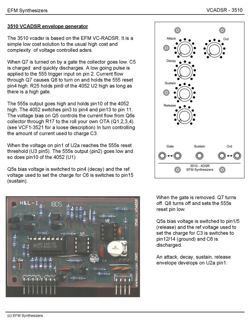
The Roland
voice fully
synthesizer.
Juno-60 is 61 key, 6
programmable polyphonic
•The Juno-60 includes memory capacity
to retain up to 56 different synthesizer
patches. (8 patches x7banks)
•Any program in memory can be tempo-
rarily edited during live performance,
•The Juno-60 features battery back up
system to retain the programs even when
switched off.
•The Tape Memory interface allows any
patch programs to be saved into an ordi-
nary tape recorder for storage and later
retrieval.
•If connecting the Pedal Switch to the
PATCH SHIFT jack, you can call the 8
patch programs stored in the same bank
one after another, simply by pressing the
pedal.
•The digitally controlled oscillator (DCO)
guarantees an extremely stable pitch.
•This is the complete 6voice polyphonic
synthesizer provided with 6VCF's, 6
VCA'sand6 ENVs.
•Wide variations of the Arpeggio Patterns
are available by changing the MODE and
RANGE switches.
•The Chorus effect produces rich and ex-
pansive sounds.
•Transposition to any key is possible by
the Transpose function.
•The Juno-60 can be driven by the MC-A
micro-composer by using its PCB con-
nector.
•It is necessary for you to understand the
functions of the controls and selectors of
the Juno-60 perfectly to fufly enjoy the
advantages of the unit. Some setting
examples are shown in this manual to
make it easier for you to master how to
operate the Juno-60, but you are the one
who creates the sounds. Please find out
your own setting and new ways of play-
ing.
<Important
)
•Please do not turn the Power switch on
immediately after turning it off; wait for
afew seconds.
Contents
Basic Connections 5
Functions 6
I. Memory Functions 6
Memory 6
Tape Interface 9
II. Functions for Sound Creating ... 12
DCO 12
HPF 14
VCF 14
VCA 16
ENV 16
LFO 17
I. Functions for Playing 18
Keyboard 18
Controllers 18
Arpeggio 19
Hold 20
Key Transpose 20
Remote Controls 21
IV. Effects 22
Chorus 22
Other Effects (Optional) 22
'Arpeggio Sample 23
1Sample Sounds 24
1Sound Synthesis Memo 29
Specifications 32
Options 33
Basic
Connections
nac www wm mdu. *c* mows
MD ^O
"Refer to P.8 ,P. 11<
Refer to P. 21 Refer to P. 9Refer to
P.21
PEDAL SWITCH
DP-2
Refer to P. 21
TUNE adjust knob (±14 note)
STEREO HEADPHONES
RH-10
•Adjust the volume with the
Volume control knob on
theJuno-60.
FOOT VOLUME
FV-200
Refer to P.21
M3
i,.
KEYBOARD AMP M/H
AUDIO AMP H
RECORDING UNIT H
P.A. MIXER L/M/H
GUITAR AMP L/M
etc.
I.Memory Functions 6
The Juno-60 includes enough memory capaci-
ty to retain up to 56 different patch programs
which you can change from one to another
during five performance just by flick of a
button.
Also, you can edit any patch program in use
by moving the controls. It also features
battery back-up circuit to retain the programs
even when switched off.
-MEMORY
WCH 'MNK-
i«h tm a*
TAPE
SAVE WEWFV LOAD
in
firm
j* 4 • *ta
EEEXEO
©BANK buttons
®PATCH NUMBER buttons
©Program Number Display window
©MANUAL button
(D WRITE button
<Tape lnterface>
©SAVE button &indicator
®VERIFY button &indicator
(D LOAD button &indicator
(a) Selecting
You can select apatch from memory by using
aBANK button ©and aPATCH NUMBER
button (3). In this case, you may push either
the BANK button or PATCH NUMBER
button first. Also, you can change only BANK
NUMBER or PATCH NUMBER. If you wish
to choose Bank (§) or ©, hold the Bank
button (E) down, and press ©or (2).
The selected Program number is shown in
the Program Number Display window (3).
All 56 patches are user programmable, but
are pre-programed to provide you with
examples and programs ready to be used.
(Refer to P. 24)
Example
•23 (Bank: 2, Patch: 3) •71 (Bank: 7, Patch: 1}
Hold [j] down, then press j"2~l
1«l Iffl I4•
D®ZDD
minicm
i
mi tm i« •
cam®
afrmim
i
E3 "7 /
iI
(b) Editing
You can edit any patch program in use as you
play. If you move adesired control even
slightly, its setting position of that patch pro-
gram will be deleted and ready to be manually
controlled. As soon as you start editing, the
two dots in the Program Number Display
window will iight, showing that the Juno-60
is in Edit mode.
This Editing function may be used as are-
time performance control since it does net
automatically rewrite the existing prograr%
unless the appropriate operation for rewrit-
ing is done. {Refer to P. 6} Therefore, 1
selecting the same patch program later, yea
will hear the original tone color unchanged.
E3
o
m°= •*•*-**—
V
*
ill fi-nnr. in
WSM
-Tv-,jfea'Wcf It=£<—0—
f
cfl faffcf 'fejJ5=fl=f
;
E^=> "^p^pJ Sp•£ ===:
t-
=t III CDZ
9E
*Adjust the desired controls.
23. The points will light.
*Editing does not affect the original patch program.
(c) Writing
You can write anew patch or an Edit (b) into
memory. The settings of the knobs (covered
red) and the position of the OCTAVE
TRANSPOSE switch are memorized as a
patch program. (Refer to the diagram below).
The old patch program previously stored m
automatically deleted when you have com-
pleted writing anew patch.
b: I6616k»|Ii c-iif feom MIS'E MM£« flMI cfc
*=nj=#;—i~
-—--c
Operation
1. Press the MANUAL button and set the
controls as you like. Otherwise, select a
patch program by BANK and PATCH
NUMBER buttons and edit its tone color.
2. Set the MEMORY PROTECT switch on
the rear pane! to OFF.
3. Press the WRITE button©.
4. While holding the WRITE button down,
press aBANK and aPATCH NUMBER
buttons.
Now you have correctly written apatch
program into memory.
5. Set the MEMORY PROTECT switch to
ON.
*When writing an Edit, press the same
BANK and PATCH NUMBER buttons, and
the original patch program wiii be replaced
with the Edit. If you press adifferent
BANK and PATCH NUMBER buttons,
both the initial patch and the editted patch
will be retained.
8
(Sound Synthesizing)
4
tic
4
TWTCH
Pr
warn mm HITCH
D+D.D
ON Off O*
The Juno-60 features battery back-up sys-
tem to retain the programs even when
switched off. The batteries should be
replaced with anew set in every five years.
In this case, please have your local Roland
dealer replace thebatteries.
(The first replacement might be required
before five years.)
(d) Copy function
This copy function allows the user to copy
any patch program and arrange the program
numbers. There may be some patch programs
which are more often used than others. If
these patches are collected in the same bank,
it will be easier to decide where to write anew
patch, which after all save agreat deal of work
and time.
*This function is particularly useful when
the Patch Shift function (Refer to P. 21 )is
being used.
Copying apatch from 23 to 17.
^3
nBCEECE
V
Burn
ixddbdd®
Hold this button down.
<Tape lnterface> 9
The Juno-60 features the Tape Interface sys-
tem which allows rts patch programs to be
saved into an ordinary tape recorder. There-
fore, countless tone colors can be ready to be
used.
Connections
SAVE
TAPE
VERIFY, LOAD
TAPE —
SAVE LOAD
LINE IN
MIC IN
i
f"
LINE OUT
\/
J
EAR >—
MONITOR ooBB
Mil
TAPE RECORDER TAPE RECORDER
Operations
•Saving (the patch program into atape recorder)
1. Set the tape recorder to REC (recording
mode).
REC PLAY
REC
2. Press the SAVE button® of the Juno-60.
SAVE
D
The SAVE indicator will light up and the
program number shown in the Display
window will go out. Also, the Pilot tone
will be sent from the SAVE jack.
3. If your tape recorder features the recording
volume adjust knob, adjust it so that the
Pilot tone registers near dB.
ovu
In 4or 5seconds the Juno-60 produces a
Modulated tone, i.e. saving into atape
recorder begins. {Be sure to complete ad-
justing the recording level before the
Modulated tone is heard.)
If the SAVE indicator goes out and the
Program Number Display window shows
double dash (—)(Manual mode), saving
is completed. (All this takes approx. 50
sec.)
10
4. Stop the tape recorder.
If you wish to stop saving in the middle,
press the MANUAL button ©
MAMJAi.
D
STOP
Verifying
1. Set the tape so that it will be played back
from the very beginning of the recorded
Data (where you hear aPilot tone).
*If you use a tape recorder with the play
back volume, set it to about amedium
level.
2. Set the tape recorder to PLAY (playing
mode) and press the VERIFY button© of
the Juno-60.
If you wish to stop verifying in the mid-
dle, press the MANUAL button ©of the
Juno-60.
MANUAL
3. Stop the tape recorder.
PLAY VERIFY
D
The VERIFY indicator lights up and the
Program Number Display window will go
out, i.e. the recorded Data will be sent
back and its accuracy will be checked.
Press the VERIFY button before the
Modulated tone is heard.
STOP
If there is an error in your recorded Data,
the Program Number Display window will
show Er (Error).
•If the VERIFY indicator goes out and the
Program Number Display window shows
the double dashes (—), verifying is com-
pleted. (All this takes approx. 50 sec) Er
11
*If there is an error ..
.
Repeat the Verify procedure taking care of
the following points.
(1} Be sure to press the VERIFY button
while the Pilot tone is heard.
(2) Be sure to adjust the play back level of
the tape recorder.
(3) Check if connections are made correctly.
If there was an error in the very beginning of
the Verify procedure, particularly take care of
(1). If the Verify procedure did not complete
even after 1minute, (2), (3) are particularly
required.
*If the above procedures were all correctly
done, it is likely that there is something
wrong with the tape.
•If the error (Er) is again indicated ..
.
Carefully repeat the Save procedure.
*If the error is indicated again and again no
matter how many times you try ..
.
•Replace with anew tape.
•Clean and demagnetize the head of the
tape.
•Use adifferent tape recorder and repeat
the same procedure again.
*Preserving the Data Tape ..
.
Please do not keep the Data recorded tape in
aplace of high temperature or humidity or
near astrong magnetic unit such as aspeaker
or an amplifier.
Loading (Sending the recorded Data back to the Juno450)
1. Set the tape so that "rt will be played back
from the very beginning of the Data (where
you hear aPilot tone).
2. Set the MEMORY PROTECT switch on
the rear panel of the Juno-60 to OF F.
ON OFF ON
3. Set the tape recorder to PLAY (play
mode), then press the LOAD button (8) of
the Juno-60.
*If you wish to stop Loading in the middle,
press the MANUAL button®.
4. When the Loading is completed, set the
MEMORY PROTECT switch to ON and
stop the tape recorder.
ON OFF ON STOP
PLAY LOAD
D
The LOAD indicator will light up and the
Program Number Display window becomes
blank, showing that loading the Data has
started.
Be sure to press the LOAD button before
the Modulated tone is heard.
*If there is an error ..
.
Carefully repeat the Load procedure.
Be sure to set the play back level of the tape
recorder to an appropriate level and press the
LOAD button at the right moment.
If the LOAD indicator goes out and the
Program Number Display window shows
double dashes (—), the Loading is com-
pleted.
II .Functions for Sound Creating
DCO DCO is the digitally controlled oscillator that
(D totally Control Oidllatar} controls the pitch and creates three types of
waveforms which are the sound source of
the synthesizer. Compared to VCO {Voltage
Controlled Oscillator}, DCO has superior
stability. The operations and functions of
12
the DCO are virtually the same as those of the
VCO. ADCO does not, however, provide
portament function, because of its digitally
controlled system.
nu
!8rD[
nj xi ru .WAVEFORMS
You can select the output waveform of
the DCO. Each switch can be individually
turned on and off and can be used with
other switches.
©PWM Mode switch
When it is set to MAN, pulse width can be
fixed. When it is set to LFO or ENV, pulse
width is controlled by* the corresponding
signal from the LFO or the Envelope Gene-
rator.
(3) PWM •Pulse Width Modulation knob
When PWM Mode switch @is set to MAN,
this knob controls the pulse width, and con-
trols the intensity of the modulation when ft
is set to LFO or ENV.
SUB OSC •Sub Oscillator Level knob
It controls the volume of the SUB OSC.
(5) LFO •LFO Modulation knob
It adjusts the depth of the vibrato effect
when the LFO is controlling the pitch of the
DCO.
©NOISE •NOISE level knob
It controls the volume of the NOISE.
<Pulse Wave>
When the top and bottom portions of the
square wave are unequal, the result is what is
called apulse wave. The harmonic content of
the pulse wave will depend greatly on the
width of the pulses. It is possible to modulate,
or change the pulse width by means of the
LFO or the envelope generator.
13
Waveform
Setting
o
181
Waveform
n\t
Saw Tooth
mir
Square
JUU
Pulse
Description
The sawtooth wave contains
afundamental sine wave and
its integral harmonic sine
waves at afixed ratio. The
level of each harmonic is as
shown on the right. When
fundamental content is 1,
the content of nth harmonic
isl/n.
The square wave contains a
fundamental sine wave and
its odd numbered harmonics
at afixed ratio. The level of
each harmonic is the same as
sawtooth wave: the content
of nth harmonic is 1/h;
except that there are no even
numbered harmonics.
With pulse wave, the har-
monic content greatly varies
depending on the pulse
width. It is characterized by
alack of the nth harmonic
series when the pulse width
is 1/n. The example on the
left lacks 3rd, 6th, and 9th
harmonics because the pulse
width is 1/3 (33%).
Harmonic Content
£-j TTTT-r-t
F2345678
JQ nn
F 3 5 7
PULSE WIDTH
at 33% (1/3)
mn-,
F 2 4 5 78
Square wave one octave lower than the DCO's (||_|
)
Pulse Width Manual PWM
PWM MODE SWITCH ©MAN
PULSE WIDTH Determine the Pulse width.
50S5 FLTLTb
PWM by LFO
PULSE MODE SWITCH ©+LFO
PULSE WIDTH MODULATION (3) >
Adjusts the intensity of the modu-
lation.
LFO
SIGNAL
OUTPUT
WAVE-
FORM nnnnnnn
PWM by ENV
PWM MODE SWITCH (2) +ENV
PULSE WIDTH MODULATION ®-+
Adjusts the intensity of the modu-
lation.
ENV
SIGNAL
OUTPUT
WAVE-
FORM
=ii§=
nnnnnnn 101
^2
HPF
(HJflh P«b Firtar)
This filter lets the high frequency harmonics
pass and cuts off the low frequency harmo-
nics. As this ftiter is not voltage controlled.
Cutoff Point is changed by only moving the
knob.
14
©FREQ •Cutoff Frequency knob
This knob sets the Cutoff point of the HPF.
In its lowest position, the DCO output passes
the filter unchanged. As you raise the knob,
Cutoff point will be boosted and only the
higher harmonics are passed.
VCF
(Vottape Controlled Filter)
This filter changes the tone color by cutting
off or emphasizing harmonics. This filter lets
the low frequency harmonics pass and cuts off
the high frequency harmonics, and is con-
trolled by avoltage.
(2) FREQ •Cutoff Frequency knob
This knob is to change the Cutoff Point of the
VCF. As you lower the knob, the frequency
in the high pitch range will be cut off, and the
sound will fade out when the waveform be-
comes nearest to a Sine Wave.
»n^=? +RefertoP.15
(3) RES «Resonance knob
This control emphasizes the Cutoff Point set
by Cutoff Frequency knob 2.As you raise
the knob, certain harmonics are emphasized
and the created sound will become more
unusual more electronic in nature. If you alter
the Cutoff Frequency knob while the Reso-
nance knob is set to ahigh level, you can
create atype of sound that is attainable only
from asynthesizer, if you raise the Resonance
knob up to the maximum, the VCF will start
Self Oscillation.
(§) ENV •Envelope Modulation knob
When the Cutoff Point of the VCF is being
modulated by the output of the Envelope
Generator, this knob is used to adjust the
intensity of the modulation. You can change
the Cutoff Point of the VCF in each note with
the ADSR pattern previously set. So the
tone color of one note can be changed quite
drastically.
(5) Polarity switch
This is the selector switch for the polarity
of the Envelope. When it is set at reverse
polarity, the ADSR pattern will be reversed
and the tone color alteration will be the other
way round.
*This often means the Cutoff Frequency of
the VCF (HPF) will need to be set higher.
©LFO •LFO Modulation knob
When the Cutoff Point of the VCF is being
modulated by the output CV of the LFO,
this knob adjusts the depth of the growl or
wan effects.
®KYBD •Key follow knob
When the Cutoff Point is being controlled
by the KYBD-CV (Keyboard control voltage),
this knob adjusts the level of the KYBD-CV.
It prevents any inconsistency in the harmonic
content caused by pitch alteration. Conse-
quently this knob is usually set to the maxi-
mum on such along keyboard, but can be set
to your taste.
NOTE
*The Self-oscillation of the VCF does not
gurantee an accurate pitch. Therefore, you
cannot expect acorrect scale when playing
the keyboard.
*If using the VCF Self-oscillation as asound
source, its pitch may turn out unstable.
In such acase, move the position of the
FREQ knob until you get astable pitch.
(If you store it into memory and use it
later, its pitch will be stable.)
Cutoff Frequency
cz
cz
cz
15
Frequency (Hz)
Resonance
Frequency (Hz)
ENV Modulation
Positive Polarity "*"
Voltage (V)
yNegative Polarity
Voltage (V)
NOTE
When modulating the VCF using the Enve-
lope, set the knob (5) to afairly low level in
case of positive porality, and set it to a fairly
high ievef in case of negative. Otherwise there
will be little effect.
VCA
(Voltage Controlled Amplifier)
ENV
(Envelope Generator)
This is to control the volume {amplitude) of
the sound, and is normally controlled by the
output voltage from the Envelope Generator.
©Control Signal Selector switch
This switch enables you to select whether to
control the VCA by the signal from the Enve-
lope Generator or by the Gate signal.
This generates the Control Voltage applied to
the VCF and the VCA, thereby controlling
the volume and the tone color of each note.
This output voltage is generated whenever you
press akey.
16
VCA level knob
This adjust the depth of the ENV modulation,
(the amount of the ENV signal)
*This knob can be used to match the ampli-
tudes (the volume sounds to your ears) of
all the patch programs. This makes the live
performance much more comfortable as
there will be no volume difference realized
between two different patches. While writ-
ing apatch into memory, adjust its level
with this knob.
*When this knob is set too high, asound
distortion might occur, but this is not be-
cause of the trouble of the Juno-60.
©@
(D A(Attack Time) knob
This sets the time required for the voltage
to reach its maximum from the moment the
key is pressed down.
®D(Decay Time) knob
This determines the time required for the
voltage to drop from the maximum to the
sustain level. When the sustain level is high,
the Envelope curve does not change by
adjusting the Decay Time.
IENV OUTPUT
(ADSR)
(§) S(Sustain Level) knob
This knob determines the Sustain Level to
which the voltage falls at the end of the Decay
Time.
(6) R(Release Time) knob
This sets the time needed for the voltage to
reach zero.
KYBD
GATE
OFF
17
The variation of each knob.
Attack Time
Setting of ADSR and Envelope Curve.
V
Time (sec)
Decay Time and Release Time
A
55
Time (sec)-L
Sustain Level
I^
I
Voltage
*in the figure shown above, the positions of
the knobs are not meant to be exactly correct,
so the knob position does not necessarily cor-
respond with the time and the voltage.
••When ail of the ADSR sliders are set to
zero, the waveform will be an extremely
short Pulse wave, and only ashort "click"
ts heard. Please be careful.
LFO
(Low Frequency Oscillator)
This oscillator generates only low frequency
signal. It controls the VCO and the VCF to
produce vibrato and growl effects.
peuar TWO
MTX vm. MODE
©®
©RATE knob
This adjusts the rate of LFO.
®TRIG MODE •TRIGGER MODE switch
You can select whether to operate the LFO
manually or automatically.
®DELAY TIME knob
This sets the time needed for the LFO to start
to function. The function varies depending
on the position of the TRIGGER MODE
switch®.
^""^-^TRIG MODE
DELAY TIME^^^^
AUTO
Or Or
MANUAL
em
—
a
J*
m
ii
^o
LFO always functions. The LFO works while the
LFO TRIGGER button is
being pressed ,and stops when
the button is released.
KJ
Tlm.
=Other than
The LFO does not start to
function until the Delay Time
set with the DELAY TIME
has passed. (*}
While the TRIGGER button
is being pressed, the LFO
amplitude becomes larger.
When the delay time set pre-
viously has passed, it becomes
norma! amplitude.
This Delay function works only in non-
legato manner. So the Delay Time affects
only the first key in alegato section.
HI .Functions for Playing
KEYBOARD The Roland Juno-60 has 5octaves and 61
keys, but can be played as a7octave key-
board (as shown below} by using the TRANS-
POSE switch. When the TRANSPOSE switch
is set to Normal, the third Cfrom the bottom
18
corresponds to the Middle Cof apiano key-
board. So, if you wish to use the Juno-60
with the other keyboards, this knowledge
will help you to align the Middle Cof the
two keyboards.
llfflfflPHMlW
Piano
Keyboard
The Keyboard of
the Juno-60
CONTROLLERS
©-
TKAttSKltf
©VOLUME knob
®OCTAVE TRANSPOSE switch
By setting this switch to Hor L, you can
transpose up or down by one octave. How
this switch is set can be written into memory.
©LFO TRIG button
The LFO Modulation can be turned on and
off with this button, if the LFO TRIGGER
MODE switch is at (MANUAL) position.
(Refer to P. 17}
m
n
-©
©Bend sens knobs
ADCO
When the pitch of the DCO is being controlled
with the ©BENDER, this knob adjusts the
variable range of the pitch.
AVCF
When the Cutoff Point of the VCF is being
controlled with the BENDER, this knob
adjusts the variable range of the tone altera-
tion.
®BENDER lever

Other manuals for JUNO-60

3

Other Roland Synthesizer manuals

Roland Orchestra M-OC1 User manual

Roland

Roland Orchestra M-OC1 User manual

Roland GR-33 User manual

Roland

Roland GR-33 User manual

Roland MKS-50 User manual

Roland

Roland MKS-50 User manual

Roland SH-101 User manual

Roland

Roland SH-101 User manual

Roland JX-3P User manual

Roland

Roland JX-3P User manual

Roland Gaia SH-01 User manual

Roland

Roland Gaia SH-01 User manual

Roland vk09 User manual

Roland

Roland vk09 User manual

Roland GR-700 User manual

Roland

Roland GR-700 User manual

Roland Groovebox MC-505 User manual

Roland

Roland Groovebox MC-505 User manual

Roland GAIA 2 User manual

Roland

Roland GAIA 2 User manual

Roland JX-1 User manual

Roland

Roland JX-1 User manual

Roland GW-7 User manual

Roland

Roland GW-7 User manual

Roland E-10 User manual

Roland

Roland E-10 User manual

Roland Piano Plus HP-30 User manual

Roland

Roland Piano Plus HP-30 User manual

Roland JX-10 User manual

Roland

Roland JX-10 User manual

Roland SPV-355 User manual

Roland

Roland SPV-355 User manual

Roland RS-50 User manual

Roland

Roland RS-50 User manual

Roland JX-8P User manual

Roland

Roland JX-8P User manual

Roland SYSTEM-100M 165 Operating and maintenance manual

Roland

Roland SYSTEM-100M 165 Operating and maintenance manual

Roland SH-101 User manual

Roland

Roland SH-101 User manual

Roland RS-50 Technical manual

Roland

Roland RS-50 Technical manual

Roland E-38 User manual

Roland

Roland E-38 User manual

Roland AX-Synth User manual

Roland

Roland AX-Synth User manual

Roland SH-09 Operating and maintenance manual

Roland

Roland SH-09 Operating and maintenance manual

Popular Synthesizer manuals by other brands

Flame Tame Machine manual

Flame

Flame Tame Machine manual

Shock Electronix Modatron Modulator Build guide

Shock Electronix

Shock Electronix Modatron Modulator Build guide

Mungo Enterprises State Zero Reference manual

Mungo Enterprises

Mungo Enterprises State Zero Reference manual

Behringer Victor quick start guide

Behringer

Behringer Victor quick start guide

Pittsburgh Modular Foundation 3.1 Manual and patch guide

Pittsburgh Modular

Pittsburgh Modular Foundation 3.1 Manual and patch guide

Oberheim OB 12 operating manual

Oberheim

Oberheim OB 12 operating manual

Giga-tronics Series 12000A Operation manual

Giga-tronics

Giga-tronics Series 12000A Operation manual

SPITFIRE AUDIO BT PHOBOS user manual

SPITFIRE AUDIO

SPITFIRE AUDIO BT PHOBOS user manual

Wurlitzer 200 Service manual

Wurlitzer

Wurlitzer 200 Service manual

Tubbutec 6equencer user manual

Tubbutec

Tubbutec 6equencer user manual

Modor NF-1 user manual

Modor

Modor NF-1 user manual

Elby Designs ASM321 Construction guide

Elby Designs

Elby Designs ASM321 Construction guide

Korg MONOPOLY POLYSIX MS-20 Owner's manual supplement

Korg

Korg MONOPOLY POLYSIX MS-20 Owner's manual supplement

Yamaha PSR-S550 owner's manual

Yamaha

Yamaha PSR-S550 owner's manual

Trax RetroWave R-1 owner's manual

Trax

Trax RetroWave R-1 owner's manual

Korg X3 Service manual

Korg

Korg X3 Service manual

Novation Bass Station II user guide

Novation

Novation Bass Station II user guide

Yamaha DX1 owner's manual

Yamaha

Yamaha DX1 owner's manual

manuals.online logo
manuals.online logoBrands
  • About & Mission
  • Contact us
  • Privacy Policy
  • Terms and Conditions

Copyright 2025 Manuals.Online. All Rights Reserved.