Roland R-09 Operating and maintenance manual

SERVICE NOTES
Issued by RJA
Copyright © 2006 ROLAND CORPORATION
All rights reserved. No part of this publication may be reproduced in any form without the written
permission of ROLAND CORPORATION.
Printed in Japan (0400) (SC-KWS)17058420E0
Apr. 2006 R-09
Table of Contents
Specifications .....................................................................2
Location of Controls .........................................................4
Location of Controls Parts List........................................5
Exploded View ..................................................................6
Exploded View Parts List.................................................7
Disassembly Procedure ....................................................8
Parts List ...........................................................................10
Checking the Version Number......................................12
Factory Reset Instructions..............................................12
System Software Updating Instructions ......................12
Test Mode.........................................................................14
Block Diagram .................................................................22
Circuit Board (TOP BOARD 1/2) .................................24
Circuit Board (TOP BOARD 2/2) .................................25
Circuit Board (CENTER BOARD 1/2) .........................26
Circuit Board (CENTER BOARD 2/2) .........................27
Circuit Diagram (TOP BOARD 1/4) ............................28
Circuit Diagram (TOP BOARD 2/4) ............................30
Circuit Diagram (TOP BOARD 3/4) ............................32
Circuit Diagram (TOP BOARD 4/4) ............................34
Circuit Diagram (CENTER BOARD 1/2) ....................36
Circuit Diagram (CENTER BOARD 2/2) ....................38
Circuit Diagram (BOTTOM BOARD) ..........................40
Messages...........................................................................40

2
Apr. 2006 R-09
Specifications
Recorder Part
●
Tracks
2 (stereo)
●
Signal Processing
AD/DA conversion: 24 bits, 44.1/48 kHz
●
Data Type
<For Recording> * Stereo only
Format MP3 (MPEG-1 audio layer 3)
Sampling Rate 44.1/48 kHz
Bit Rates 64/96/128/160/192/224/320 kbps
Format WAV
Sampling Rate 44.1/48 kHz
Bit Depth 16/24 bits
<For Playback>
Format MP3 (MPEG-1 audio layer 3)
Sampling Rate 32/44.1/48 kHz
Bit Rates 64/96/128/160/192/224/256/320 kbps or
VBR (Variable Bit Rate)
Format WAV
Sampling Rate 32/44.1/48 kHz
Bit Depth 16/24 bits
●
Memory Card
SD Memory Card (supports 64 MB--2 GB)
* Each recording time is approximate. The times may change depending on the
card specifications.
* In case that there are plural files, the sum of recording time would be shorter
than above.
Input/Output
●
Audio Inputs
Internal Stereo Microphone
Mic input (Stereo miniature phone type, plug-in powered mic)
Line input (Stereo miniature phone type)
* The Internal/External MIC and the LINE IN can’t be used at the same time;
only the LINE IN is effective.
●
Audio Outputs
Phones (Stereo miniature phone type)
Digital Out Connector (Optical miniature phone type)
* Phones and Digital Out use a common jack.
●
Nominal Input Level (Variable)
Mic Input: -36dBu (Default input level)
Line Input: 0dBu (Default input level)
●
Input Impedance
Mic input: 20 k ohms
Line input: 17 k ohms
●
Output Level
25 mW (In case 16 ohms load)
●
Recommended Load Impedance
16 ohms or greater
●
Frequency Response
20 Hz-22 kHz
●
USB Interface
Mini-B type
* support USB 2.0/1.1 mass storage device class
Effects
●
Playback Reverb
4 types (Hall 1, Hall 2, Room, Plate)
Recording Time unit: minutes
Settings 64MB 128MB 512MB 1GB 2GB
WAV (16 bits/44.1 kHz) 5 11 44 88 180
WAV (16 bits/48 kHz) 5 10 40 81 166
WAV (24 bits/44.1 kHz) 3 7 29 59 120
WAV (24 bits/48 kHz) 3 7 27 54 110
MP3 128 kbps 62 126 490 980 1,993
MP3 224 kbps 35 72 280 560 1,139
MP3 320 kbps 25 50 196 392 797

3
Apr. 2006 R-09
Others
●
Display
128 x 64 dot graphic display
●
Power Supply
AC Adaptor, Alkaline dry battery LR6 (AA) type x 2, or Nickel Hydrogen
battery (HR15/51) x 2
●
Current Draw
360 mA
●
Dimensions
62.6 (W) x 102 (D) x 29.1 (H) mm
2-1/2 (W) x 4-1/16 (D) x 1-3/16 (H) inches
●
Weight
145 g / 6 oz (including batteries and memory card.)
●
Accessories
Owner’s Manual English (#73233756)
AC Adaptor (#03679478)
AC Cord Set
For 117V U/CS: 120V 1.0M (NON POLAR) (#02562456)
For 230V E/EU: 230V 1.0M FOR PSB (#01903356)
EURO CONVERTER PLUG ECP01-5A (#00905234)
For 240V A: SC-078-NA05 240VA (#03785590)
SD Memory Card (64 M bytes) (#04232278)
USB cable (Mini-B type) (#03788289)
* 0 dBu = 0.775 V rms
* Expected AA alkaline life under continuous use:
Continuous playback: approximately 5.5 hours
Continuous recording: approximately 4 hours
(These figures will vary depending on the actual conditions of use.)
●
Options
OP-R09C: Cover Stand Set for R-09
fig.OP-R09C_80
OP-R09M: Mic Stand Adaptor for R-09
fig.OP-R09M1_80
CB-R09S: Carrying Case for R-09
fig.CB-R09S_80
CS-15: Stereo Microphone
fig.CS-15_80

4
Apr. 2006 R-09
Location of Controls
fig.panel-front_85
1
2
4
8
12
13
56 7
9
10
11
14
15
16
2
17
24
20
21
22
19
23
25
3
18
23

5
Apr. 2006 R-09
Location of Controls Parts List
No PART
CODE
PART NAME1 DESCRIPTION1 Q’TY
1 04230367 KEYTOP POWER 1
2 04230445 S-KEYTOP SX2H PM 1
3 04230512 SIDE PANEL L 1
4 04128501 DC JACK HEC3600-010510 1
5 04230467 MIC COVER L 1
6 04230456 MIC COVER A 2
7 04230478 MIC COVER R 1
8 04230389 DISPLAY COVER 1
9 04230567 TOP PANEL 1
10 04230556 TOP CASE 1
11 ******** LED (LED) TLSU1002A(TO2) 1
* This part is included in #73129145 TOP BD ASSY.
12 04230423 C-KEYTOP SX3H 1
13 04230434 KEYTOP KEY CURSOR 1
14 04233190 RUBBER SHEET 1
* If the feel of button operations near [ ] is poor, replace this part.
15 04230378 KEYTOP REC 1
16 03348078 3.5MM JACK W/OPTICAL GP1FD310TP0F 1
17 04233412 S-KNOB BLK/RED 1
18 04230523 SIDE PANEL R 1
19 04233245 FOOT 2
20 04230545 S-KNOB SLV 4
21 04230356 BOTTOM PANEL 1
22 04230334 BOTTOM CASE 1
23 40344167 SCREW 2X6 BINDING P-TITE FE BZC 3
24 04129312 3.5MM JACK LGY2209-0101FC 2
25 73238667 BATTERY CVR-TMNL PM ASSY 1

6
Apr. 2006 R-09
Exploded View
fig.bunkai-e
26
18
30
17
29
28
7
1
10
13
11
12
13 16
15
19
25
31
24
27
2
3
5
6
4
8
9
14 20
22
22
21
These are included in
#19 CENTER BOARD ASSY.
These are included in
#19 CENTER BOARD ASSY.

7
Apr. 2006 R-09
Exploded View Parts List
No PART CODE PART NAME DESCRIPTION1 Q’TY
1 04230567 TOP PANEL 1
2 04230389 DISPLAY COVER 1
3 04230556 TOP CASE 1
4 04230423 C-KEYTOP SX3H 1
5 04230434 KEYTOP KEY CURSOR 1
6 04233190 RUBBER SHEET 1
* If the feel of button operations near [ ] is poor, replace this part.
704230378 KEYTOP REC 1
10 73129145 TOP BD ASSY 1
* This unit includes the following parts.
8******** DISPLAY LCD E-55028WHJ-AAN 1
9 ******** DISPLAY HOLDER 1
11 04230512 SIDE PANEL L 1
12 04230367 KEYTOP POWER 1
13 04230445 S-KEYTOP SX2H PM 2
14 04230290 BATTERY HOLDER 1
15 04233412 S-KNOB BLK/RED 1
16 04230523 SIDE PANEL R 1
17 73238667 BATTERY CVR-TMNL PM ASSY 1
18 04230501 BATTERY COVER SHAFT 1
19 73233989 CENTER BOARD ASSY 1
20 04230467 MIC COVER L 1
21 04230478 MIC COVER R 1
22 04230456 MIC COVER A 2
24 73233990 BOTTOM BOARD ASSY 1
25 04236501 WIRING 20624 SFWR-P=0.5-K1-6-50 connects #24 Bottom BD to #19 Center BD 1
26 04230334 BOTTOM CASE 1
27 04233245 FOOT 2
28 04230356 BOTTOM PANEL 1
29 04230545 S-KNOB SLV 4
30 40344167 SCREW 2X6 BINDING P-TITE FE BZC 3
31 04450878 BOTTOM CUSHION 1
* This part has been added from serial number “A**3000.”

8
Apr. 2006 R-09
Disassembly Procedure
Detaching the BOTTOM PANEL
1.
The bottom panel is secured in place with double-sided tape at the
location shown by dotted lines in the figure. Peel off carefully in the
direction of the arrow.
* The bottom panel may deform or crack. In such cases, placing a part order for a
bottom panel is required.
fig.bottom-panel_85
Detaching the TOP CASE and
BOTTOM CASE
2.
Remove the screws at the three locations shown in the figure.
fig.top-case-screw_85
3.
Place so that the top panel is at the top, then lift up the top case to remove.
fig.top-case-remove_85
Detaching the TOP BOARD
4.
Because this is secured in place by a circuit board to circuit board
connector, grasp and remove the top board without applying twisting
force to the connector.
fig.top-board-remove_85
Detaching the CENTER BOARD
and BOTTOM BOARD
5.
Turn upside-down, use tweezers or the like to flip up the lock tabs at the
circled areas, then remove the BATTERY HOLDER while disengaging the
locks.
fig.battery-holder_85

9
Apr. 2006 R-09
6.
Flip up the tabs in the circled areas and remove the CENTER BOARD.
fig.center-board-remove_85
7.
For the BOTTOM BOARD as well, remove while flipping up the tabs
holding the BOTTOM BOARD in place.
fig.bottom-board-remove_85

10
Apr. 2006 R-09
Parts List
CASING
# 73238667 BATTERY CVR-TMNL PM ASSY 1
# 04230356 BOTTOM PANEL 1
# 04230512 SIDE PANEL L 1
# 04230523 SIDE PANEL R 1
# 04230567 TOP PANEL 1
# 04230501 BATTERY COVER SHAFT 1
# 04230389 DISPLAY COVER 1
# 04230456 MIC COVER A 2
# 04230467 MIC COVER L 1
# 04230478 MIC COVER R 1
# 04230334 BOTTOM CASE 1
# 04230556 TOP CASE 1
CHASSIS
#04230290 BATTERY HOLDER 1
KNOB, BUTTON
#04233412 S-KNOB BLK/RED 1
# 04230545 S-KNOB SLV 4
# 04230367 KEYTOP POWER 1
# 04230423 C-KEYTOP SX3H 1
# 04230434 KEYTOP KEY CURSOR 1
# 04230378 KEYTOP REC 1
# 04230445 S-KEYTOP SX2H PM 2
JACK, EXT TERMINAL
04128501 DC JACK HEC3600-010510 on CENTER BOARD 1
# 04129312 3.5MM JACK LGY2209-0101FC on CENTER BOARD 2
03348078 3.5MM JACK W/OPTICAL GP1FD310TP on CENTER BOARD 1
PWB ASSY
#73233990 BOTTOM BOARD ASSY 1
# 73129145 TOP BD ASSY 1
# 73233989 CENTER BOARD ASSY 1
* This unit includes the following parts.
04128501 DC JACK HEC3600-010510 1
# 04129312 3.5MM JACK LGY2209-0101FC 2
03348078 3.5MM JACK W/OPTICAL GP1FD310TP 1
# 04233189 TERMINAL COVER 1
# 04230301 BATTERY TERMINAL M 1
# 04230312 BATTERY TERMINAL P 1
WIRING, CABLE
# 04236501 WIRING 20624 SFWR-P=0.5-K1-6-50 connects Bottom BD to Center BD 1
SCREWS
40344167 SCREW 2X6 BINDING P-TITE FE BZC 3
PACKING
#04233901 PACKING PAD LOWER
# 04230278 PACKING PAD UPPER 1
# 04230267 PACKING CASE JAPANESE 1
# 04233345 PACKING CASE ENGLISH 1
MISCELLANEOUS
# 04233190 RUBBER SHEET 1
* If the feel of button operations near [ ] is poor, replace this part.
# 04233245 FOOT 2
# 04233189 TERMINAL COVER on CENTER BOARD 1
# 04230301 BATTERY TERMINAL M on CENTER BOARD 1
# 04230312 BATTERY TERMINAL P on CENTER BOARD 1
# 40674989 DOUBLE FACED TAPE #500 W5MM X L30MM -
# 04450878 BOTTOM CUSHION 1
* This part has been added from serial number “A**3000.”

11
Apr. 2006 R-09
ACCESSORIES (Standard)
03788289 USB CABLE MINI-B U4A5B-100S 1.0M 1
# 04232278 IC CARD RP-SD064BRL0 1
# 73129090 OWNER’S MANUAL JAPANESE 1
40232334 WARRANTY CARD MOCHIKOMI JAPAN ONLY 1
# 73233756 OWNER’S MANUAL ENGLISH 1
03679478 AC ADAPTOR PSB-6U (WITHOUT AC CORD) 1
01903334 AC CORD SET 100V 1.0M FOR PSB-1U For 100V 1
02562456 AC CORD SET 120V 1.0M (NON POLAR) For 117V U, 117V CS 1
01903356 AC CORD SET 230V 1.0M FOR PSB For 230V E, 230V EU 1
00905234 EURO CONVERTER PLUG ECP01-5A For 230V E, 230V EU 1
03785590 AC CORD SET SC-078-NA05 240VA For 240V A 1

12
Apr. 2006 R-09
Checking the Version
Number
1.
Turn off the power to the R-09.
2.
While holding down the [ ] button, turn on the power.
3.
A screen like the one shown below appears, enabling you to verify the
versions of the programs.
fig.version_90
Program
: Version of the main program
Booter
: Version of the bootup program
Updater
: Version of the updater program
4.
Press the [FINDER/MENU] button to return to the MENU screen.
Factory Reset Instructions
Factory Reset restores to their factory defaults any parameter values changed
via the setup menu, as well as the input and output level setting values.
1.
Turn on the power to the R-09.
2.
Press the [FINDER/MENU] button for a while until the MENU screen
appears.
3.
Move the cursor to “
8 Factory Reset
,” then press the [REC] button.
The Factory Reset screen appears.
fig.factory_90
4.
Press the [REC] button to execute the Factory Reset, or press the
[FINDER/MENU] button to cancel it.
5.
“
Are you sure ?
” is displayed. Select “
Yes
” to execute or “
No
” not to
execute, then press the [REC] button.
fig.factory-sure_90
When the Factory Reset finishes, the Menu screen automatically returns.
Note for User Data
Parameter values set via the Menu screen and input and output level setting
values are saved in memory when the power is switched off, but they cannot
be saved in a file or extracted as user data.
System Software Updating
Instructions
Copy the system-update files on the UPDATE CD-ROM to an SD card inserted
into the R-09, then update the system.
Items Required
• An SD card (blank)
• PC equiped with an USB connector
• The USB cable attached with R-09
• AC adaptor
• UPDATE CD-ROM (#17041866)
Creating an update SD card
To create an update-use SD card, you first format the SD card. Formatting is
performed on the R-09.
1.
Turn on the power to the RC-09.
2.
Press the [FINDER/MENU] button for a while until the MENU screen
appears.
3.
Move the cursor to “
7 SD Card
,” then press the [REC] button.
4. Move the cursor to “2 Format,” then press the [REC] button.
fig.sdmenu_90
5. “Are you sure ?” is displayed. Select “Yes” to execute formatting.
fig.sdformat_90
6. When formatting has finished, press the [FINDER/MENU] button
several times to return to the basic screen.
This completes formatting of the SD card. Next, copy the system-update file.

13
Apr. 2006 R-09
7. Connect the PC to the R-09 with the USB cable.
8. Display the SD card for the R-09 on the PC’s screen, then copy the system-
update file to the root directory of the SD card.
Four types of system-update files are available.
DMZ15.UPD: Update for all blocks
DMZ15_BOT.UPD: Update for the Boot block
DMZ15_UPD.UPD: Update for the Updater block
DMZ15_PRG.UPD: Update for the Main Program block
9. When copying is finished, refer to the R-09 Owner’s Manual and follow
the instructions in “Disconnecting the PC” (p. 59) to disconnect the R-09
from the PC.
10. Turn off the power to the R-09.
System Update Procedure
When performing a system update, be sure to use the AC adaptor. If this is
attempted using battery power, a low battery during the procedure may cause
the update to fail and cause the unit not to operate correctly.
Never disconnect the AC adaptor while the update is in progress. Doing so
may corrupt the system and cause the unit to fail to operate correctly.
1. Turn off the power to the R-09.
2. Using the update-use SD card created according to the procedure
described in the section of “Creating an update SD card,” insert the
update-use SD card into the card slot in the R-09.
3. While holding down the [REC] button, turn on the power.
When a valid update-use file is found on the SD card, the Program
Update screen like the one shown below appears.
* The screen that is displayed differs according to the type of update-use file.
DMZ15.UPD (update for all blocks)
fig.upd-all_90
DMZ15_BOT.UPD (update for the Boot block only)
fig.upd-boot_90
DMZ15_UPD.UPD (update for the Updater block only)
fig.upd-updr_90
DMZ15_PRG.UPD (update for the Main Program block only)
fig.upd-prg_90
If no SD card is inserted, a screen like the one below appears.
fig.nocard_90
If no valid update-use file exists on the SD card, a screen like the one below
appears.
fig.nofile_90

14
Apr. 2006 R-09
4. Pressing the [REC] button starts the update.
When the update starts, the PEAK LED and REC LED flash in
alternation and the contents of the flash ROM are erased.
fig.erase_90
Next, the update file is written.
fig.write_90
Be very sure never to disconnect the AC adaptor while the operation is in
progress. When the update finishes, a screen like the one shown below
appears.
fig.complete_90
5. Switch off the power to finish the system-update operation.
Corrective Action if the System
Update Fails
If a problem occurs during the update, the REC LED flashes and a message
appears on the screen.
fig.err1_90
<< Unsuccessful erasing of the flash ROM >>
fig.err2_90
<< Unsuccessful writing to the flash ROM >>
If one of these errors occurs, take corrective action as described below.
Of the four types of updates, if one of the errors just described occurs during
the procedure for DMZ15_PRG.UPD (updating the Main Program block), then
disconnect the AC adaptor and redo the update operation.
DMZ15.UPD (for updating all blocks)
DMZ15_BOT.UPD (for updating the Boot block)
DMZ15_UPD.UPD (for updating the Updater block)
If the error occurred during the procedure for one of these, disconnect the AC
adaptor and replace the TOP BOARD ASSY (#73129156).
Test Mode
Items Required
• An SD card (formatted on R-09)
• AC adaptor
• Headphones
• Plug-in power mic
• PC equiped with an USB connector
• Audio equipment or oscillator
• Digital optical cable (plug type: mini <-> square)
• Monitor speaker equiped with digital input (e.g. EDIROL MA-10D)
When executing Test mode, be sure to use the AC adaptor.
Entering Test Mode
1. Turn off the power to the R-09.
2. Set the switches on the back of the unit as shown in the figure below.
fig.test-sw-select
3. While holding down the [FINDER/MENU] button and the [REPEAT]
button at the same time, turn on the power.

15
Apr. 2006 R-09
Exiting Test Mode
1. While in Test mode, hold down the [FINDER/MENU] button and press
the [ ] button several times to move to “12. Factory Reset.”
The next screen appears.
fig.test12-1_90
2. Press the [REC] button to execute Factory Reset.
fig.test12-2_90
When processing finishes, the screen automatically changes. If an SD
card is inserted, a screen like the one shown below appears.
fig.test13-1_90
3. Eject the SD card, and when a screen like the one shown below appears,
switch off the power.
fig.test13-2_90
When the power is off and the screen has gone completely blank, disconnect
the AC adaptor.
Skipping test items
To move among the test items, use the [ ] and [ ] buttons. If you want
to proceed to the next without executing tests for any items, hold down the
[FINDER/MENU] button and use the [ ] and [ ] buttons to make the
selection.
Test Items
In Test mode, you perform testing for the following items.
1. Checking Version
2. Device Test
3. Analog (External Mic) Test
4. Analog (LINE) Test
5. Recording and Playing
6. Switch/LED Test
7. Display Test
8. USB Test
9. Digital Out Test
10. Analog (Internal Mic) Test
11. Noise Test
12. Factory Reset
1. Checking Version
Entering Test mode displays the version-confirmation screen.
fig.test01-1_90
Prog: Program version and relevant information
Boot: Bootup program version
Updt: Update program version
After verifying the version, use the [ ] button to advance to the next item.

16
Apr. 2006 R-09
2. Device Test
Entering this item automatically starts testing of each device.
fig.test02-1_90
Insert a formatted SD card into the card slot. On insertion, checking is
resumed, and operation automatically advances to the next item unless a
problem is found.
fig.test02-2_90
Test descriptions
Flash: This verifies the checksum of the flash-ROM program area.
SDRAM: This checks read/write access to the SDRAM.
RTC Clock: This checks whether the oscillator for the internal clock is
oscillating correctly.
M66592: This checks read/write access to the registers for the M66592
USB controller.
SD Card: This checks write to the SD card.
(After the check is completed, the content written to the SD
card by the test is erased.)
If a test fails, “NG” is displayed for the corresponding item.
fig.test02-3_90
3. Analog (External Mic) Test
This checks the throughput of input from the external microphone jack to
output.
Make the connection to the external microphone input jack (MIC).
Microphone input is impossible when nothing is connected or when the
connection is made to the line input jack (LINE IN). In such cases, a screen like
the one shown below is displayed.
fig.test03-1_90
<<Connect an external microphone. >>
fig.test03-2_90
<< Disconnect the device connected to the line input jack (LINE IN). >>
When the correct connection is made, a screen like the one shown below
appears.
fig.test03-3_90
Connect headphones and check the audio input from the microphone. After
verifying, use the [ ] button to advance to the next item.
At this time, input gain adjustment (the INPUT LEVEL button) and output
volume-level adjustment (the VOLUME button) do not function. If the volume
level of the sound heard through the headphones is too low, make sure the
MIC GAIN switch on the back of the unit is set to HIGH.

17
Apr. 2006 R-09
4. Analog (LINE) Test
This checks the throughput of input from the line input jack (LINE IN) to
output.
Entering this item displays a screen like the one shown below.
fig.test04-1_90
Connect the output from an audio device or an oscillator to the line input jack
(LINE IN). When the connection is made, a screen like the one shown below is
displayed.
fig.test04-2_90
Check the audio input with headphones. After verifying, use the [ ] button
to advance to the next item.
At this time, input gain adjustment (the INPUT LEVEL button) and output
volume-level adjustment (the VOLUME button) do not function. Adjust the
volume level of the audio device (or oscillator) so as not to damage your
hearing.
5. Recording and Playing
Entering this item displays a screen like the one shown below.
fig.test05-3_90
If an SD card is not inserted, or if the SD card is locked, a screen like the one
shown below appears.
fig.test05-1_90
<< No card is inserted. >>
fig.test05-2_90
<< The card is locked. Undo the lock switch on the SD card and reinsert
the card. >>
Next, carry out the test with the output of the audio device or oscillator
connected to the line input jack (LINE IN).
Pressing the [REC] button starts recording of the audio signal input from the
line input jack (LINE IN).
fig.test05-4_90
The audio signal is not output to the digital output connector (OPTICAL)
during recording, but this is not a malfunction.
After recording for approximately 3 seconds, playback starts automatically.
fig.test05-5_90
Make sure the recorded audio signal is played back.
If playback is correct, press the [ ] button to advance to the next item.

18
Apr. 2006 R-09
6. Switch/LED Test
Entering this item displays a screen like the one shown below.
fig.test06-1_90
Make sure the PEAK and REC LEDs are lighted.
Next, press all buttons and switches except [POWER] one at a time. Slide the
slider switches to both ON and OFF.
If the buttons and switches function correctly, their “ ” indicators on the
screen change to “ .”
* Pressing the [REPEAT] button makes the PEAK LED go dark, and pressing the
[REC] button makes the REC LED go dark.
fig.test06-2_90
After verification that all buttons and switches function correctly, operation
automatically advances to the next item.
7. Display Test
Entering this item displays a screen like the one shown below.
fig.test07-1_90
Press the [ ] button to start the test.
There are five test screens. Press the [ ] button to move to the next test
screen. To go back, press the [ ] button.
fig.test07-2_90
fig.test07-3_90
fig.test07-4_90
fig.test07-5_90
INPUT
LEVEL (+/-)
FINDER REPEAT
EXT MIC TYPE AGC
REVERB
REC
VOLUME (+/-)
MIC GAIN
HOLD
LOW CUT

19
Apr. 2006 R-09
At the final screen, testing of contrast adjustment is performed.
fig.test07-6_90
Use the [ ] button and the [ ] button to check whether the contrast
changes. Also make sure that the values at the bottom of the screen change
from 1 to 10.
Use the [ ] button to advance to the next item.
If the contrast values 1 and 10 are not checked, moving to the next item is
impossible, even when the [ ] button is pressed.
8. USB Test
While a screen like the one shown below is displayed, connect the PC and the
R-09 using a USB cable.
fig.test08-1_90
When the connection is made, a screen like the one shown below appears.
fig.test08-2_90
If an SD card is not inserted, a screen like the one shown below appears. Insert
an SD card.
fig.test08-3_90
Make sure the R-09 is seen as a USB drive on the PC‘s screen.
After verifying, disconnect the USB cable. Operation automatically advances to
the next item.
Moving to a different test item is not possible while the USB connection is
made. To move, first end the USB connection.
9. Digital Out Test
This checks the throughput from the external microphone input jack (MIC) to
the digital output connector (OPTICAL).
Make the connection to the external microphone input jack (MIC).
Microphone input is impossible when nothing is connected or when
something is connected to the line input jack (LINE IN). In such cases, a screen
like the one shown below is displayed.
fig.test09-1_90
<< Connect an external microphone. >>
fig.test09-2_90
<< Disconnect the device connected to the line input jack (LINE IN). >>

20
Apr. 2006 R-09
When the correct connection is made, a screen like the one shown below
appears.
fig.test09-3_90
Connect the digital output connector (OPTICAL) to a device that has a digital
input and check the microphone input audio.
After finishing verification, use the [ ] button to advance to the next item.
At this time, input gain adjustment (the INPUT LEVEL button) and output
volume-level adjustment (the VOLUME button) do not function. If the volume
level of the sound heard from the connected device is too low, make sure the
MIC GAIN switch on the back of the unit is set to HIGH.
10. Analog (Internal Mic) Test
This performs testing of the internal microphone.
When something is connected to the external microphone input jack (MIC) or
the line input jack (LINE IN), use of the internal microphones becomes
impossible and a screen like the one shown below is displayed.
fig.test10-1_90
Disconnect the device connected to the external microphone input jack (MIC)
or line input jack (LINE IN).
When use of the internal microphones becomes possible, a screen like the one
shown below is displayed.
fig.test10-2_90
Input audio toward the left and right internal microphones and make sure
sound is heard from both the left channel and the right channel of the digital
output connector (OPTICAL). After finishing verification, use the [ ]
button to advance to the next item.
11. Noise Test
This performs testing for residual noise.
Entering this item displays a screen like the one shown below.
fig.test11-1_90
Use headphones to carry out checking to determine whether audible noise is
heard from the headphones jack.
After finishing verification, use the [ ] button to advance to the next item.
12. Factory Reset
This returns the settings to their factory defaults.
Entering this item displays a screen like the one shown below.
fig.test12-1_90
Pressing the [REC] button starts processing.
fig.test12-2_90
When processing finishes, operation automatically advances to the next item.
If an SD card is inserted, a screen like the one shown below appears.
fig.test13-1_90
Other manuals for R-09
2
Table of contents
Other Roland Voice Recorder manuals

Roland
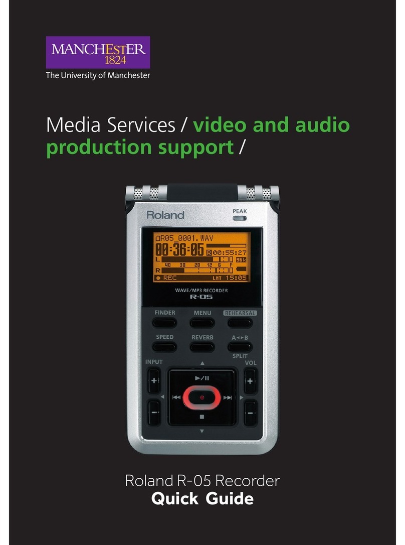
Roland Edirol R-05 User manual

Roland
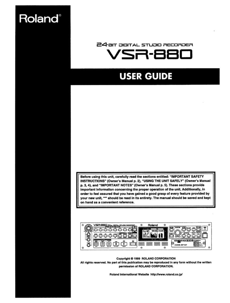
Roland VSR-880 User manual

Roland
Roland BR-900CD Troubleshooting guide

Roland
Roland BR-1200CD Operating and maintenance manual

Roland
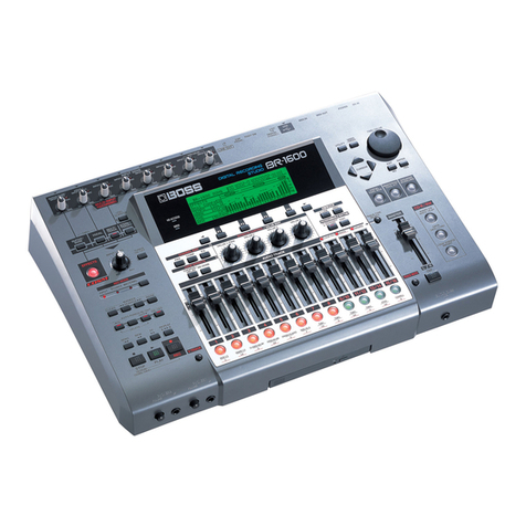
Roland BR-1600CD Operating and maintenance manual

Roland
Roland R-09 User manual

Roland
Roland BOSS BR-600 Manual

Roland
Roland R-4 PRO - ANNEXE 109 Technical manual

Roland
Roland BR-800 User manual

Roland
Roland Edirol R-1 Service manual