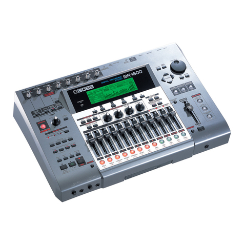
Roland BR-1200CD Operating and maintenance manual

SERVICE NOTES
Issued by RJA
Copyright © 2005 ROLAND CORPORATION
All rights reserved. No part of this publication may be reproduced in any form without the written permission
of ROLAND CORPORATION.
Printed in Japan (0500) (NB)17058313E0
Feb. 2005 BR-1200CD
TABLE OF CONTENTS
CAUTIONARY NOTES ...................................................2
SPECIFICATIONS.............................................................2
LOCATION OF CONTROLS ..........................................4
LOCATION OF CONTROLS PARTS LIST ...................5
EXPLODED VIEW ............................................................6
EXPLODED VIEW PARTS LIST .....................................7
WIRING FORMING .........................................................8
PARTS LIST......................................................................10
CHECKING THE VERSION NUMBER.......................15
USERS DATA SAVE AND LOAD................................15
TEST MODE.....................................................................17
INITIALIZING ALL BR-1200CD SETTINGS (INITIALIZE)
....20
SYSTEM SOFTWARE UPDATING INSTRUCTIONS
....23
BLOCK DIAGRAM.........................................................24
CIRCUIT BOARD (MAIN BOARD).............................26
CIRCUIT DIAGRAM (MAIN BOARD POWER) .......28
CIRCUIT DIAGRAM (MAIN BOARD ANALOG) ....30
CIRCUIT DIAGRAM (MAIN BOARD PHANTOM)
....30
CIRCUIT DIAGRAM (MAIN BOARD CPU)..............32
CIRCUIT DIAGRAM (MAIN BOARD DSP)...............34
CIRCUIT DIAGRAM (MAIN BOARD DIGITAL OUT)
...36
CIRCUIT DIAGRAM (MAIN BOARD USB)...............36
CIRCUIT BOARD (ANALOG BOARD) ......................37
CIRCUIT DIAGRAM (ANALOG BOARD).................38
CIRCUIT BOARD (SW SHEET) ....................................40
CIRCUIT DIAGRAM (SW SHEET,SW BOARD)........42
CIRCUIT DIAGRAM (SW SHEET,GUITAR INPUT BOARD)
....44
CIRCUIT DIAGRAM (SW SHEET,+5V POWER BOARD)
...45
CIRCUIT BOARD (CD CN BOARD) ...........................46
CIRCUIT DIAGRAM (CD CN BOAR).........................46
ERROR MESSAGES ........................................................47

2
Feb. 2005 BR-1200CD
CAUTIONARY NOTES
User data status
User data status after each of the following processes is described below.
Whenever carrying out procedures that involve deleting or erasing user data,
always be sure to back up the user data to some form of external media (refer
to Saving and Loading Data).
* Executing Test Mode during Factory Reset deletes the user data.
PARTS LIST
Due to one or more of the following reasons, parts with parts code ********
cannot be supplied as service parts.
• Part supplied only as a component in a complete assembly
• Copyright does not permit the part to be supplied
• Part is sold commercially
CIRCUIT BOARD
NIU meant that “NOT IN USE “ there don’t set any contents in the Circuit
Diagram.
There has silk-screen only in the Circuit Board.
SPECIFICATIONS
BR-1200CD: Digital Recording Studio
Tracks
Track: 12 V-Track: 192 (16 V-Tracks per each Track)
Up to 2 tracks can be recorded simultaneously, and up to 12 tracks can be
played back simultaneously.
Maximum Useful Capacity/Recording Time
Internal Hard Disk:
40 G bytes (recording time; 120 hours) (conversion in one track)
* The recording time is approximate. Times may be slightly shorter depending on
the number of songs and size of imported loop phrase that were created.
* The recording time is the total for all the tracks that are used. If each of the
twelve tracks contain an equal amount of data, the length of the resulting song
will be approximately 1/12 of the above.
Signal Processing
AD Conversion: 24 bit, AF Method (Guitar/Bass)
24 bit,
∆∑
Modulation (VOCAL)
24 bit,
∆∑
Modulation (SIMUL)
24 bit,
∆∑
Modulation (LINE)
DA Conversion: 24 bit,
∆∑
Modulation
Internal Processing: 24 bit (digital mixer section)
Recording Data: 16 bit linear
Sample Rate
44.1 kHz
Frequency Response
20 Hz-20 kHz (+1/-3 dB)
Total Distortion
0.05% or less
(INPUT SENS: CENTER, 1 kHz at nominal output level)
Nominal Input Level (Variable)
GUITAR/BASS jack: -20 dBu
MIC 1, 2 jacks (TRS balanced/XLR): -40 dBu
LINE IN jacks: -10 dBu
Input Impedance
GUITAR/BASS jack: 1 M ohms
MIC 1, 2 jacks: 12.5 k ohms (HOT-COLD)
(TRS balanced/XLR) 6.5 k ohms (HOT-GND, COLD-GND)
LINE IN jack: 22 k ohms
Nominal Output Level
LINE OUT jacks: -10 dBu
Output Impedance
LINE OUT jack: 2 k ohms
PHONES jack: 100 ohms
Recommended Load Impedance
LINE OUT jack: 20 k ohms or greater
PHONES jack: 8-50 ohms
Residual Noise Level
LINE OUT jack: -87 dBu or less
(INPUT SELECT:GUITAR/BASS, input terminated with 1 k ohms, INPUT
SENS: CENTER, IHF-A, typ.)
Process User Data
Checking Version number Preserved
Factory Reset Deleted
System Update Preserved
Test Mode Preserved

3
Feb. 2005 BR-1200CD
Interface
DIGITAL OUT: S/PDIF 16-24 bit (optical type)
USB connector (B type)
Display
64 x 40 mm (Backlit LCD)
Connectors
MIDI IN connector
MIDI OUT connector
USB connector
DIGITAL OUT connector (optical type)
FOOT SW jack (1/4 inch phone type)
EXP PEDAL jack (Stereo 1/4 inch phone type)
LINE OUT jacks (RCA Phono type)
LINE IN jacks (RCA Phono type)
MIC 1, 2 jacks (TRS balanced/XLR)
PHONES jack (Stereo 1/4 inch phone type)
GUITAR/BASS jack (1/4 inch phone type)
Power Supply
DC 12 V; Supply AC Adaptor (Roland PSB-3U)
Power Consumption
3.0 A
Dimensions
478 (W) x 297 (D) x 95 (H) mm
18-7/8 (W) x 11-3/4 (D) x 3-3/4 (H) inches
Weight
4.1 kg / 9 lbs 1 oz (Excluding AC Adaptor)
Accessories
AC Adaptor: PSB-3U (#02900423)
AC Cord : 120V (#00894378)
: 230V (#00894389)
: 240VE (#00907001)
Owner’s Manual :English (#72902990)
:Japanese (#72898789)
Roland Service (information sheet) (#********)
CD-ROM “DISCRETE DRUMS” (#03891601)
Options
Expression Pedal: EV-5 (Roland)
Foot Volume/Expression: FV-300L
Foot Switch: FS-5U
Pedal Switch: DP-2 (Roland)
* 0 dBu = 0.775 Vrms
* In the interest of product improvement, the specifications and/or appearance of
this unit are subject to change without prior notice.

4
Feb. 2005 BR-1200CD
LOCATION OF CONTROLS
fig.panel
d
17
d b b
2342218
d
3
33 1
24
25 26 27
a
c b
28 29 30 31 e e
33
32 32
4
1
8
1188212019
4
6
2
1
7
12
3
12
17
14
12
15
3
3
3
1
5
10
15
13
12
1
17
16

5
Feb. 2005 BR-1200CD
LOCATION OF CONTROLS PARTS LIST
[PART]
[SCREW]
NO PART CODE CATEGORY PART NAME DESCRIPTION Q’TY
1 00900145 KNOB,BUTTON D S-KEYTOP SD1H BLK 1
01904112 DIODE LED(RED) SLR-342VCT32 N.P.Q RANK 1
01340290 SWITCH TACT SWITCH EVQ11A H=5.0 1
2 00900156 KNOB,BUTTON D S-KEYTOP SD2H BLK 2
01904112 DIODE LED(RED) SLR-342VCT32 N.P.Q RANK 2
01340290 SWITCH TACT SWITCH EVQ11A H=5.0 2
3 00900189 KNOB,BUTTON D S-KEYTOP SX1H BLK 1
01340290 SWITCH TACT SWITCH EVQ11A H=5.0 1
4 00900190 KNOB,BUTTON D S-KEYTOP SX2H BLK 2
01340290 SWITCH TACT SWITCH EVQ11A H=5.0 2
5 00904245 KNOB,BUTTON D S-KEYTOP SX3H BLK 3
01340290 SWITCH TACT SWITCH EVQ11A H=5.0 3
6 00904256 KNOB,BUTTON D S-KEYTOP SX4H BLK 4
01340290 SWITCH TACT SWITCH EVQ11A H=5.0 4
7 01234090 KNOB,BUTTON D T-KEYTOP MX4B BLK 1
01340290 SWITCH TACT SWITCH EVQ11A H=5.0 1
8 01670512 KNOB,BUTTON F C-KEYTOP SX1H BLK 1
01340290 SWITCH TACT SWITCH EVQ11A H=5.0 1
9 22485303 KNOB,BUTTON D R-KNOB(ALPHA-DIAL) L BLK 248-303 1
01905467 ENCODER ROTARY ENCODER EVE GC1 F20 24B 1
10 01783945 KNOB,BUTTON N S-KEYTOP MD3H 1
01904112 DIODE LED(RED) SLR-342VCT32 N.P.Q RANK 1
15029348 DIODE LED (GREEN) SLR-342MCT32 1
01340290 SWITCH TACT SWITCH EVQ11A H=5.0 3
11 01783923 KNOB,BUTTON N S-KEYTOP MD1H 1
01340290 SWITCH TACT SWITCH EVQ11A H=5.0 1
12 02013090 KNOB,BUTTON F C-KEYTOP MX1H CLR 1
03786756 DIODE LED SML76755WN-TP15 1
01340290 SWITCH TACT SWITCH EVQ11A H=5.0 1
13 01902289 KNOB,BUTTON U S-KNOB M BLK LCG 1
01677312 POTENTIOMETER 45M/M SLIDE POTENTIOMERTER EWAP1AC10 B54 (50KB/MS) 1
14 01891801 KNOB,BUTTON U R-KNOB S1 LCG BLK 1
03783023 POTENTIOMETER 9M/M ROTARY POTENTIOMETER EVUJFUFK315D 100KRD 1
15 02457512 KNOB,BUTTON J R-KNOB SFA BLK/LCG 1
02896712 POTENTIOMETER 9M/M ROTARY POTENTIOMETER EVUF2KFK4B54 50KB 1
16 03125589 KNOB,BUTTON M R-KNOB MF-ELA BLK/LCG 1
03789645 POTENTIOMETER POTENTIOMETER EVUF2KFK3B54 1
17 00785856 DIODE LED SLR-342VR3F 1
18 03785190 CASING DISPLAY COVER 1
02565034 DISPLAY UNIT LCD F-51320GNY-LY-AA 1
15029347 DIODE LED (RED) SLR-342VC3F 1
15039237 DIODE LED(GREEN) SLR-342MC3F 1
19 01340412 KNOB,BUTTON P R-KNOB SF-A BLK/LCG 1
02900467 POTENTIOMETER 9M/M ROTARY POTENTIOMETER EVJC25FB6A54 50KAX2 1
20 00569278 JACK,EXT TERMINAL 6.5MM JACK LGR4609-7100 1
21 13449252 JACK,EXT TERMINAL 6.5MM JACK YKB21-5006 (STEREO W/SW) 1
22 03785201 MISCELLANEOUS PANEL SHEET 1
23 03785156 CASING TOP CASE 1
24 22360712 MISCELLANEOUS CORD HOOK 236-712 1
25 02900312 JACK,EXT TERMINAL DC JACK HEC0470-01-640 1
26 32490595 KNOB,BUTTON P S-KEY MX BLK 1
03891678 SWITCH PUSH SWITCH SPUP190300 1
27 02781189 JACK,EXT TERMINAL USB CONNECTOR YKF45-0021 1
28 13429825 JACK,EXT TERMINAL MIDI CONNECTOR YKF51-5054 2PZ 1
29 03454101 JACK,EXT TERMINAL IC (OPTICAL) GP1FA313TZ 1
30 00569278 JACK,EXT TERMINAL 6.5MM JACK LGR4609-7100 1
31 03453290 JACK,EXT TERMINAL RCA(PIN) YKC21-3488N 1
32 00569278 JACK,EXT TERMINAL 6.5MM JACK LGR4609-7100 1
33 03459223 JACK,EXT TERMINAL XLR CONNECTOR JY-5033A 1
NO PART CODE PART NAME DESCRIPTION Q’TY
a 40127689 SCREW 3X10 BZC BIDING TAPTITE S BZC 1
b 40012534 SCREW 3X6 BZC BIDING TAPTITE S BZC 3
c 40011378 SCREW 4X8 BZC BIDING TAPTITE S BZC 1
d 40011312 SCREW 3X8 BZC BIDING TAPTITE P BZC 5
e 40233012 SCREW 2.6X8 BZC BIDING TAPTITE P BZC 4
6
Feb. 2005 BR-1200CD
EXPLODED VIEW
fig.explo-A
Fig.1
Fig.3 Fig.4
Fig.2
5
67
89
11
12
10
10
27 28
29
30
F
C
F
20
20 20
20 21
22
A
B
C
C
D
D
H
EA
25 26
23
24
13
C
14 15
16
G
I
G
BJ
17
Please refer to Fig.2
Please refer to Fig.3
Please refer to Fig.4
Please refer to Fig.5

7
Feb. 2005 BR-1200CD
fig.explo-C
EXPLODED VIEW PARTS LIST
[PARTS] [SCREW]
Fig.5 Fig.6
1
2
3
4
1
11
18 G
19
Please refer
to Fig.6
No Part Code Part Name Description
1 02013090 F C-KEYTOP MX1H CLR
2 01783945 N S-KEYTOP MD3H
3 01783923 N S-KEYTOP MD1H
4,13,16 72898834 SW SHEET ASSY
NOTE: ‘SW SHEET ASSY’ includes the following parts.
4 ******** SW BOARD ASSY
13 ******** 5V POWER BOARD ASSY
16 ******** GUITAR BOARD ASSY
5 01891801 U R-KNOB S1 LCG BLK
6 22485303 D R-KNOB(ALPHA-DIAL) L BLK 248-303
7 03785190 DISPLAY COVER
8 03125589 M R-KNOB MF-ELA BLK/LCG
9 32490595 P S-KEY MX BLK
10 01902289 U S-KNOB M BLK LCG
11 03785201 PANEL SHEET
12 01340412 P R-KNOB SF-A BLK/LCG
14 72898812 MAIN BOARD ASSY
15 72899078 ANALOG BOARD ASSY
17 02565034 LCD F-51320GNY-LY-AA
18 03785178 CHASSIS
19 03785156 TOP CASE
20 22355334 FOOT MKS 235-334
21 03785189 BOTTOM COVER
22 72899267 CD CN PCB ASSY
23 03786823 CDRW HOLDER
24 03785701 DVD DRIVE UNIT UJDA760RL-A
25 22360712 CORD HOOK 236-712
26 32490595 P S-KEY MX BLK
27 03459645 HDD COLLAR COLLAR
28 03896301 HDD INSULATOR
29 03789445 HARD DISK ST340014A
30 03345945 HDD HOLDER
No Part Code Part Name Description
A 40012534 SCREW 3X6
BINDING TAPTITE S FE BZC
B40011312 SCREW 3X8
BINDING TAPTITE P BZC
C40012512 SCREW 3X6
BINDING TAPTITE S ZC
D40455867 SCREW M2X2.5 PAN MACHNE W/SW
E 40011378 SCREW M4X8
BINDING TAPTITE S FE BZC
F40563112 SCREW 6-32X1/2 UNIFY
G 40011278 SCREW 3X8
BINDING TAPTITE P FE ZC
H 40127689 SCREW M3X10
BINDING TAPTIGHT S TYPE FE BZC
I40457245
PLAIN WASHER 3X12X1
ZC
J 40233012 SCREW M2.6X8
BINDING TAPTITE P BZC

8
Feb. 2005 BR-1200CD
WIRING FORMING
fig.BR1200-TOP
fig.A
fig.BR1200-HDD
1.
5V POWER (5V POWER WIRING #03785389) ···Please lay it down low to
Chassis side.
2.
HDD IDE (WIRING HDD IDE #02904623) ···Move up to the BOTTOM
direction. Please note the connector doesn’t come off.
3.
HDD POWER (WIRING HDD POWER #03893789) ···Don’t expand and
reform operation internally.
fig.B
fig.BR1200-CD
4.
VR/LED BAN CARD (BNCD-P=1.25-K-34-130 #03789856) ···Don’t hit the
CD holder and fold up from connect side.
5.
CD IDE (WIRING HDD IDE #02904623) ···Fold up into board internal
side.
fig.C
fig.BR1200-ANALOG
6.
SW BAN CARD (BNCD-P=1.25-K-20-110 #03789901) ···Top of knob, don’t
lay it down to ANALOG BOARD side.
7.
GAIN/PEAK LED BAN CARD (BNCD-P=1.25-K-12-200 #03343256) ···As
same the procedure 6.
fig.D
fig.BR1200-GUITAR
8.
GUITAR CABLE (JWFV 5X175-P2.0 #02568523) ···Fit with the Chassis and
put on Filament tape #3883(#40122645) from top side.
9.
PHONES CABLE (JWFV 6X175-P2.0 #03789912) ···Fit with the Chassis
and put on Filament tape #3883(#40122645) from top side.
A
F
B
C
E
D
1
2
3
45
7
6
89

9
Feb. 2005 BR-1200CD
fig.E
fig.BR1200-NOISE
10.
Noise measure ···
The analog GND synchronizer is short-circuited in the AWG24 line.
Depends on the analog board revision since serial No. ZT34785, and the
measures do not exist.
fig.F
fig.BR1200-CU
11.
EMI measure ···
Put on the 3M bronze tape #2245(#40346367) as same the picture.
10
11

10
Feb. 2005 BR-1200CD
PARTS LIST
fig.part1e
CASING
#03785156 TOP CASE 1
# 03785189 BOTTOM COVER 1
# 03785190 DISPLAY COVER 1
CHASSIS
#03785178 CHASSIS 1
03345945 HDD HOLDER 1
# 03786823 CDRW HOLDER on CD-R 1
KNOB, BUTTON
02013090 F C-KEYTOP MX1H CLR 17
00900145 D S-KEYTOP SD1H BLK 7
00900156 D S-KEYTOP SD2H BLK 1
00900189 D S-KEYTOP SX1H BLK 10
00900190 D S-KEYTOP SX2H BLK 3
00904245 D S-KEYTOP SX3H BLK 1
00904256 D S-KEYTOP SX4H BLK 1
01234090 D T-KEYTOP MX4B BLK 1
01670512 F C-KEYTOP SX1H BLK 3
01783923 N S-KEYTOP MD1H 1
01783945 N S-KEYTOP MD3H 1
32490595 P S-KEY MX BLK 1
02457512 J R-KNOB SFA BLK/LCG 1
03125589 M R-KNOB MF-ELA BLK/LCG 3
01340412 P R-KNOB SF-A BLK/LCG 1
01891801 U R-KNOB S1 LCG BLK 2
22485303 D R-KNOB(ALPHA-DIAL) L BLK 248-303 1
01902289 U S-KNOB M BLK LCG 11
SWITCH
#03891678 PUSH SWITCH SPUP190300 SW1on MAIN 1
01340290 TACT SWITCH EVQ11A H=5.0 SW58,SW59,SW60,SW6,SW7,SW8,SW9,SW10,SW
11,SW12,SW13,SW14,SW15,SW16,SW17,SW18,S
W19,SW20,SW21,SW22,SW23,SW24,SW25,SW26,
SW27,SW28,SW29,SW30,SW31,SW32,SW34,SW3
5,SW36,SW37,SW38,SW39,SW40,SW41,SW42,SW
43,SW44,SW45,SW46,SW47,SW48,SW49,SW50,S
W51,SW52,SW53,SW54,SW55,SW56,SW57,SW58,
SW59,SW60,SW61on SW
60
JACK, EXT TERMINAL
03454101 IC (OPTICAL) GP1FA313TZ CN10 on MAIN 1
13429825 MIDI CONNECTOR YKF51-5054 2PZ JK1 on MAIN 1
02781189 USB CONNECTOR YKF45-0021 JK4 on MAIN 1
00569278 6.5MM JACK LGR4609-7100 JK2,JK3 on MAIN, JK2 on GUITAR
2+1
02900312 DC JACK HEC0470-01-640 JK5 on MAIN 1
13449252 6.5MM JACK YKB21-5006 (STEREO W/SW) JK1 on GUITAR 1
03459223 XLR CONNECTOR JY-5033A JK4,JK2 on ANALOG 2
03453290 RCA(PIN) YKC21-3488N JK5,JK7 on ANALOG 2
13449258 6.5MM JACK HLJ4306-01-3080 JK6,JK3 on ANALOG 2
DISPLAY UNIT
02565034 F-51320GNY-LY-AA LCD 1
NOTE: Replacement F-51320GNY-LY-AA should be made on a unit base.
DISK DRIVE UNIT
#03789445 ST340014A HARD DISK on HARD 1
NOTE: Replacement ST340014A should be made on a unit base.
03785701 UJDA760RL-A DVD DRIVE UNIT on CD-R 1
NOTE: Replacement UJDA760RL-A should be made on a unit base.
SAFETY PRECAUTIONS:
The parts marked have
safety-related characteristics. Use
only listed parts for replacement.
NOTE: The parts marked # are new. (initial parts)
Due to one or more of the following reasons,
parts with parts code ******** cannot be supplied as service parts.
• Part supplied only as a component in a complete assembly
• Copyright does not permit the part to be supplied
• Part is sold commercially
The description "Q'TY" means a necessary number of the parts per one product.

11
Feb. 2005 BR-1200CD
PCB ASSY
#72898812 MAIN BOARD ASSY 1
NOTE: ‘MAIN BOARD ASSY’ includes the following parts.
# 03893790 LEAF on MAIN 1
# 72898823 SW SHEET ASSY 1
NOTE: ‘SW SHEET ASSY’ includes the following parts.
# ******** SW BOARD ASSY 1
NOTE: ‘BR-1200CD SW BOARD ASSY’ includes the following parts.
12169406 LED SPACER LDS-100Y 10MM on SW 11
# ******** 5V POWER BOARD ASSY 1
NOTE: ‘BR-1200CD 5V POWER BOARD ASSY’ includes the following parts.
# 03785389 5V POWER WIRING on 5V 1
# ******** GUITAR BOARD ASSY 1
NOTE: ‘BR-1200CD GUITAR BOARD ASSY’ includes the following parts.
02568523 RIBBON CABLE JWFV 5 X 175 - P2.0 on GUITAR 1
# 03789912 RIBBON CABLE JWFV 6 X 175 - P2.0 on GUITAR 1
# 03786812 JACK HOLDER PHONES BOARD on GUITAR 1
# 72899078 ANALOG BOARD ASSY 1
# 72899267 CD CN PCB ASSY on CD-R 1
IC
#03786789 UPD703106AGJ-095-UEN IC (CPU) IC5 on MAIN 1
02900978 M66291GP IC (USB CONTROLLER) IC23 on MAIN 1
02231767 RA0A-101 (TC223C080AF-101) IC (DSP) IC20,IC19 on MAIN 2
02896745 S1L50753F27B000 IC (I/F) IC13 on MAIN 1
03670112 M11L16161SA-45T (0.18U) IC (DRAM) IC22 on MAIN 1
03341590 TC58FVM5B2ATG65BAH IC (FLASH MEMORY) IC2 on MAIN 1
03459123 M12L128168AP1L IC (SDRAM) IC7 on MAIN 1
02451434 AK4552VT IC (AD/DA) IC32 on MAIN 1
01672634 TC74HC4052AFT(EL) IC (COMS) IC9,IC6 on MAIN 2
02458045 SN74LV157APWR IC (CMOS) IC18,IC21 on MAIN 2
02675689 HD74LV245ATELL IC (CMOS) IC4,IC8,IC11 on MAIN 3
01783523 TC74VHCT245AFT(EL) IC (CMOS) IC15 on MAIN 1
# 03785601 SN74LV04APWR IC (CMOS) IC1 on MAIN 1
# 03785612 SN74AHC1G08DCR IC (CMOS) IC10 on MAIN 1
00346445 NJM2100M(TE3) IC (BIPOLAR OP AMP) IC30 on MAIN 1
01014634 TA7809F(TE16L) IC (REGULATOR) IC27 on MAIN 1
01458445 UPC29M33T-T1 IC (REGULATOR) IC25 on MAIN 1
01678512 UPC2933T-T2 IC (REGULATOR) IC26 on MAIN 1
01899790 UPC29L33T-E2 IC (REGULATOR) IC26 on MAIN 1
02563467 NJM2374AM-TE1 IC (SWITCHING REGULATOR) IC34 on MAIN 1
03784256 CS8406-CZ ZR IC (DIF/TRANSMITTER) IC17 on MAIN 1
02903745 S-80930CNMC-G80 IC (RESET) IC12 on MAIN 1
15289124 PC-400T IC (PHOTO COUPLER) IC3 on MAIN 1
02678945 BU2090 IC IC4,IC5,IC6,IC7 on SW 4
03560856 PQ1CG3032FZ IC (REGULATOR) IC1 on 5V 1
15189188 M5238AL IC (JFET OP AMP) IC2 on GUITAR 1
02346123 NJM4556AD IC (OP AMP) IC3 on GUITAR 1
15189261 M5218AFP-600E IC (BIPOLAR OP AMP) IC2,IC3,IC4,IC6 on ANALOG 4
TRANSISTOR
15309104 2SA1586-GR(TE85R) TRANSISTOR Chip on MAIN 1
03344078 2SC4738-GR(TE85R) TRANSISTOR Chip on MAIN
1+1
02900301 TPC8303(TE12L) TRANSISTOR Chip on MAIN 1
02780423 POWER MOSFET CPH6302-TL TRANSISTOR Chip on MAIN 1
00239812 DTC114EUT106 TRANSISTOR Chip on MAIN, ANALOG
3+7
02340645 RN1441-A(TE85L) TRANSISTOR Chip on MAIN, on ANALOG
1+2
#03564378 2SK879-GR(TE85L) TRANSISTOR Chip on MAIN 1
15129164 DTC114ESTP DIGITAL TRANSISTOR Q5 on SW 1
15129204 DTC343TS TP TRANSISTOR Q3,Q4 on GUITAR 2
15319107 2SC4116-GR(TE85R) TRANSISTOR Chip on ANALOG 8
15329103T0 2SK880-GR(TE85R) FET Chip on ANALOG 12
00239801 DTA114EU T-106 TRANSISTOR Chip on ANALOG 1
15329501 DTA143EK T146 TRANSISTOR Chip on ANALOG 1
DIODE
03453356 1SS362(TE85L) DIODE Chip on MAIN 2
03343090 1SS387(TPH3) SWITCHING DIODE Chip on MAIN 1
15339119T0 1SS352(TPH3) SWITCHING DIODE Chip on MAIN 1
01899723 MA111-(TX) SWITCHING DIODE Chip on MAIN, on ANALOG
1+1
02454856 RB081L-20 TE25 SCHOTTKY DIODE Chip on MAIN, on 5V
1+1

12
Feb. 2005 BR-1200CD
15019126 1SS133 T-77 SWITCHING DIODE D1,D2,D3,D4,D5,D6,D7,D8,D9,D10,D11,D12,D13
,D14,D15,D16,D17,D18,D19,D20,D21,D22,D23,D2
4,D25,D26,D27,D28,D29,D30,D31,D32,D33,D34,D
35,D36,D37,D38,D39,D40,D41,D42,D43,D44,D45,
D46,D47,D48,D49,D50,D51,D52,D53,D54,D55,D5
6,D57,D63,D64on SW,D62 on GUITAR
59
+1
00785856 SLR-342VR3F LED LED1,LED2,LED19,LED20,LED1,LED2,LED19,L
ED20,LED21,LED29,LED30,LED31,LED32on SW
9
01904112 SLR-342VCT32 N.P.Q RANK LED(RED) LED13,LED15,LED16,LED17,LED18,LED22,LED
23,LED24,LED25,LED26,LED33,LED34,LED35,L
ED36,LED37,LED38,LED39on SW
17
15029347 SLR-342VC3F LED (RED) LED28 on SW 1
15029348 SLR-342MCT32 LED (GREEN) LED14 on SW 1
15039237 SLR-342MC3F LED(GREEN) LED27 on SW 1
# 03786756 SML76755WN-TP15 LED LED3,LED4,LED5,LED6,LED7,LED8,LED9,LED1
0,LED11,LED12 on SW
10
02783023 RB500V-40 DIODE Chip on ANALOG 12
01897189 MA147-(TX) ARRAY DIODE Chip on ANALOG 6
RESISTOR
02673401 RR0816P-102-D MTL.FILM RESISTOR Chip on MAIN 1
00567378 RPC05T 473 J MTL.FILM RESISTOR Chip on MAIN, on ANALOG
4
+18
15399945 MCR100 101J RESISTOR Chip on MAIN 1
00567323 RPC05T 223 J MTL.FILM RESISTOR Chip on MAIN 1
00567289 RPC05T 103 J MTL.FILM RESISTOR Chip on MAIN, on ANALOG 23
+5
00567156 RPC05T 102 J MTL.FILM RESISTOR Chip on MAIN, on ANALOG
5 +8
00566967 RPC05T 470 J MTL.FILM RESISTOR Chip on MAIN, on ANALOG 14
+8
03453289 MCR25 JZH JL R51 MTL.FILM RESISTOR Chip on MAIN 1
# 03567712 RR0816P-303-D MTL.FILM RESISTOR Chip on MAIN, on ANALOG
2+4
01905001 RR0816P-103-D MTL.FILM RESISTOR Chip on MAIN 2
00566867 RPC05T 100 J MTL.FILM RESISTOR Chip on MAIN 2
00566912 RPC05T 220 J MTL.FILM RESISTOR Chip on MAIN 4
00566923 RPC05T 270 J MTL.FILM RESISTOR Chip on MAIN 2
00566934 RPC05T 330 J MTL.FILM RESISTOR Chip on MAIN 6
00567012 RPC05T 820 J MTL.FILM RESISTOR Chip on MAIN 2
00567023 RPC05T 101 J MTL.FILM RESISTOR Chip on MAIN, on ANALOG
2+2
00567034 RPC05T 121 J MTL.FILM RESISTOR Chip on MAIN 1
00567045 RPC05T 151 J MTL.FILM RESISTOR Chip on MAIN 1
00567178 RPC05T 152 J MTL.FILM RESISTOR Chip on MAIN 1
00567201 RPC05T 272 J MTL.FILM RESISTOR Chip on MAIN, on ANALOG
1+3
00567245 RPC05T 472 J MTL.FILM RESISTOR Chip on MAIN, on ANALOG
3+2
00567256 RPC05T 562 J MTL.FILM RESISTOR Chip on MAIN 1
01904978 RR0816P-202-D MTL.FILM RESISTOR Chip on MAIN 1
00567501 RPC05T 474 J MTL.FILM RESISTOR Chip on MAIN 1
00567556 RPC05T 105 J MTL.FILM RESISTOR Chip on MAIN, on ANALOG
2
+13
01454890 MCR50 JZH J 220 MTL.FILM RESISTOR Chip on MAIN 1
01566912 RR0816P-333-D MTL.FILM RESISTOR Chip on MAIN 1
00567412 RPC05T 104 J MTL.FILM RESISTOR Chip on MAIN, on ANALOG
16
+22
01905056 RR0816P-392-D MTL.FILM RESISTOR Chip on MAIN 1
01011856 RPC05T 0R0 J MTL.FILM RESISTOR Chip on MAIN, on ANALOG
35
+20
15409113 EXBV8V103JV RESISTOR ARRAY Chip on MAIN 4
00126112 EXBV8V101JV RESISTOR ARRAY Chip on MAIN 7
00344289 EXBV8V333JV RESISTOR ARRAY Chip on MAIN 2
00909590 EXBV8V330JV RESISTOR ARRAY Chip on MAIN 4
01011845 EXBV8V0R000V RESISTOR ARRAY Chip on MAIN 3
01013578 EXBV8V470JV RESISTOR ARRAY Chip on MAIN 20
01457145 EXBE10C103J RESISTOR ARRAY Chip on MAIN 7
13749777T0 SR25TRE 151 J CARBON RESISTOR R122,R124,R126,R128,R130,R132,R134,R136,R138,
R140,R142,R155on SW
12
13749781T0 SR25TRE 221 J CARBON RESISTOR
R121,R123,R125,R127,R129,R131,R133,R135,R137,
R139,R141,R143,R144,R145,R146,R147,R148,R149,
R150,R151,R152,R153,R154,R157,R158,R159,R160,
R161,R162,R163,R164,R165,R166,R167,R171on SW
35
13749845T0 SR25TRE 104 J 1/4W CARBON RESISTOR
R156,R168 on SW,R103,R112,R118,R119on GUITAR
2+4
03560878 MRS25CTR 3001 F MTL.FILM RESISTOR R1 on 5V 1
13799754T0 MR16 TR KF 1K METAL FILM RESISTOR R3 on 5V 1
13749765T0 SR25TRE 470 J CARBON RESISTOR R116,R111 on GUITAR 2
13749773T0 SR25TRE 101 J CARBON RESISTOR R110,R115 on GUITAR 2
13749813T0 SR25TRE 472 J CARBON RESISTOR R108,R113,R117,R120 on GUITAR 4
13749821T0 SR25TRE 103 J CARBON RESISTOR R104 on GUITAR 1
13749829T0 SR25TRE 223 J CARBON RESISTOR R109,R114 on GUITAR 2
13749869T0 SR25TRE 105 J CARBON RESISTOR R105 on GUITAR 1
# 03346734 SR25TRE 0R0 J CARBON RESISTOR C3 on ANALOG 1
00567067 RPC05T 221 J MTL.FILM RESISTOR Chip on ANALOG 2
00567267 RPC05T 682 J MTL.FILM RESISTOR Chip on ANALOG 4
00567390 RPC05T 683 J MTL.FILM RESISTOR Chip on ANALOG 4
# 03459256 MCR50JZHJ682 MTL.FILM RESISTOR Chip on ANALOG 4
DIODE

13
Feb. 2005 BR-1200CD
02678545 RR0816P-153-D MTL.FILM RESISTOR Chip on ANALOG 6
POTENTIOMETER
03783023 EVUJFUFK315D 100KRD 9M/M ROTARY POTENTIOMETER VR1,VR2 on SW 2
# 03789645 EVUF2KFK3B54 POTENTIOMETER VR3,VR4,VR5 on SW 3
02896712 EVUF2KFK4B54 50KB 9M/M ROTARY POTENTIOMETER VR6 on SW 1
01677312 EWAP1AC10 B54 (50KB/MS) 45M/M SLIDE POTENTIOMERTER VR7,VR8,VR9,VR10,VR11,VR12,VR13,VR14,
VR15,VR16,VR17on SW
11
02900467 EVJC25FB6A54 50KAX2 9M/M ROTARY POTENTIOMETER VR18 on GUITAR 1
CAPACITOR
02129534 ECJ1VB1H102K CERAMIC CAPACITOR Chip on MAIN 1
01674167 ECUV1H100DCV CERAMIC CAPACITOR Chip on MAIN 3
01674401 ECUV1H331JCV CERAMIC CAPACITOR Chip on MAIN 1
00567978 GRM39F104Z25PT CERAMIC CAPACITOR Chip on MAIN, on ANALOG 95
+5
00567945 GRM39B103K50PT CERAMIC CAPACITOR Chip on MAIN 39
01674712 ECJ1VF1A105Z CERAMIC CAPACITOR Chip on MAIN 51
01674212 ECJ1VC1H220J CERAMIC CAPACITOR Chip on MAIN 2
01674423 ECUV1H471JCV CERAMIC CAPACITOR Chip on MAIN 2
01674556 ECJ1VB1H472K CERAMIC CAPACITOR Chip on MAIN 2
01674689 ECJ1VF1H473Z CERAMIC CAPACITOR Chip on MAIN, on ANALOG
1
+12
01674190 ECJ1VC1H150J CERAMIC CAPACITOR Chip on MAIN 2
01675278 GRM39CH101J50PT CERAMIC CAPACITOR Chip on MAIN, on ANALOG 11
+2
03454889 EEE1HA010SR CHEMICAL CAPACITOR Chip on MAIN 1
03454901 EEE1HA101UP CHEMICAL CAPACITOR Chip on MAIN 1
# 03454923 EEE1HA330UP CHEMICAL CAPACITOR Chip on MAIN 1
03348445 EEE1CA471UP CHEMICAL CAPACITOR Chip on MAIN 3
03454823 EEE1CA470WR CHEMICAL CAPACITOR Chip on MAIN 3
03454789 EEE1CA220WR CHEMICAL CAPACITOR Chip on MAIN 1
02010812 ECA0JM472 CHEMICAL CAPACITOR Chip on MAIN 1
02900512 EEE1CA100SR CHEMICAL CAPACITOR Chip on MAIN 13
02345145 RV2-16V101M-R CHEMICAL CAPACITOR Chip on MAIN 13
13529132 RPE132-901F104Z50 CERAMIC CAPACITOR C1,C5,C29,C30,C31,C32,C33,C34,C101on SW, C8
on 5V,C12 on GUITAR
9+1
+1
13639698 ECEA0JKS101B (H=5MM) CHEMICAL CAPACITOR C2,C3 on SW 2
02784812 RE3-16V102M-T2 CHEMICAL CAPACITOR C6 on 5V 1
13649270 ECA1CM222B 2200UF/16V CAPACITOR C7 on 5V 1
03018545 RPE2C1H101J2M1A01A CERAMIC CAPACITOR C11,C20,C26 on GUITAR 3
03344323 RPE2C1H470J2M1Z01A CERAMIC CAPACITOR C17,C23 on GUITAR 2
01900834 RA2-16V101M-T2 CHEMICAL CAPACITOR C18,C24 on GUITAR, C10,C18,C26,C97,C98 on
ANALOG
2+5
13639549 ECA1CM470B CHEMICAL CAPACITOR C22,C16 on GUITAR, C15,C55 on ANALOG
2+2
02782901 RE3-50V010MB-T2 CHEMICAL CAPACITOR C10 on GUITAR, on ANALOG
1+2
02891767 RC2-16V100M-T2 CHEMICAL CAPACITOR C9,C14,C15,C19,C25,C28 on GUITAR, C27,C33,
C36,C37,C46,C47,C50,C60,C62,C63,C64,C77,C78,
C79,C90,C99,C102,C107,C108 on ANALOG
6
+19
02897901 RC3-25V4R7M-T2 CHEMICAL CAPACITOR C27 on GUITAR, on ANALOG
1+1
01674278 ECJ1VCH470J CERAMIC CAPACITOR Chip on ANALOG 4
01674312 ECUV1H820JCV CERAMIC CAPACITOR Chip on ANALOG 2
01674356 ECUV1H151JCV CERAMIC CAPACITOR Chip on ANALOG 2
01674389 ECJ1VC1H221J CERAMIC CAPACITOR Chip on ANALOG 6
01674489 ECJ1VB1H152K CERAMIC CAPACITOR Chip on ANALOG 4
01900845 RA2-50V470M-T2 CHEMICAL CAPACITOR C21,C23,C41,C42 on ANALOG 4
13639547M1 ECA1CM220B CHEMICAL CAPACITOR C94,C95 on ANALOG 2
13639606M0 ECEA1HM100B 10UF/50V CHEMICAL CAPACITOR C22 on ANALOG 1
INDUCTOR, COIL, FILTER
02451367 ZCYS51R5-M3PAT CHOKE COIL Chip on MAIN 1
02238234 TSL0709RA-151KR52 CHOKE COIL L37 on MAIN 1
00237212 SH-202 CHOKE COIL FL1 on MAIN 1
01565578 N1608Z601T01 FERRITE-BEAD Chip on MAIN, on ANALOG 15
+2
# 03895345 N1608ZA202T01 FERRITE-BEAD Chip on MAIN 1
12449268 BL02RN2-R62T2 FERRITE-BEAD L1,L2 on SW 2
# 03785690 ELC18B101L CHOKE L4 on 5V 1
# 03785634 TSL1315S-470K3R4-PF CHOKE L3 on 5V 1
CRYSTAL, RESONATOR
02673267 CX-49G 5MHZ CRYSTAL Chip on MAIN 1
02781412 CX-49G 6.000MHZ CRYSTAL Chip on MAIN 1
02672401 SG-8002JC 67.7376MHZ PC CRYSTAL Chip on MAIN 1
ENCODER
01905467 EVE GC1 F20 24B ROTARY ENCODER EN1 on SW 1
RESISTOR

14
Feb. 2005 BR-1200CD
CONNECTOR
02014445 20FE-BT-VK-N CONNECTOR CN7 on MAIN 1
02896934 52559-3092 CONNECTOR CN9 on MAIN 1
01908634 14FE-BT-VK-N CONNECTOR CN12 on MAIN, CN14 on ANALOG
1+1
02018990 34FE-BT-VK-N CONNECTOR CN4 on MAIN 1
13369570 B2B-PH-K-S (2P) CONNECTOR CN8 on MAIN 1
13369594 B4B-XH-A CONNECTOR CN8 on MAIN 1
03340278 B7B-PH-K-S(PB FREE) CONNECTOR CN11on MAIN 1
01909589 10FE-BT-VK-N CONNECTOR CN13 on MAIN, CN5 on ANALOG
1+1
02349545 P/N 75401-0X0-B CONNECTOR CN1,CN5 on MAIN, CN1on CD CN
2+1
02018712 20FE-ST-VK-N FOR WIRING CONNECTOR CN3 on SW 1
02564678 12FE-ST-VK-N CONNECTOR CN1 on SW 1
# 03785623 34FE-ST-VK-N CONNECTOR CN2 on SW 1
01909601 12FE-BT-VK-N CONNECTOR CN3 on ANALOG 1
13369600 52147-0510(5P) WIRE TRAP CN2 on ANALOG 1
13369601 52147-0610(6P) WIRE TRAP CN6 on ANALOG 1
03124967 KX14-50KL7.9H1 CONNECTOR CN2 on CD CN 1
WIRING, CABLE
# 03893789 WIRING HDD POWER 1
02896978 WIRING 2 LCD 1
02904623 WIRING HDD IDE 2
03343256 BAN CARD BNCD-P=1.25-K-12-200 1
# 03789856 BAN CARD BNCD-P=1.25-K-34-130 1
# 03789878 BAN CARD BNCD-P=1.25-K-10-50 1
# 03789901 BAN CARD BNCD-P=1.25-K-20-110 1
# 03789967 BAN CARD BNCD-P=1.25-K-14-50 1
SCREW
40233012 SCREW M2.6X8 BINDING TAPTITE P BZC 4
40011312 SCREW 3X8 BINDING TAPTITE P BZC 13
40011278 SCREW 3X8 BINDING TAPTITE P FE ZC 19
40127689 SCREW M3X10 BINDING TAPTIGHT S TYPE FE BZC 1
40012534 SCREW 3X6 BINDING TAPTITE S FE BZC 8
40012512 SCREW 3X6 BINDING TAPTITE S ZC 18
40011378 SCREW M4X8 BINDING TAPTITE S FE BZC 1
40457245 PLAIN WASHER 3X12X1 ZC 1
40455867 SCREW M2X2.5 PAN MACHNE W/SW on CD-R 4
40563112 SCREW 6-32X1/2 UNIFY on HARD 4
PACKING
# 03785267 PACKING CASE UPPER 1
# 03785245 ACCESORIE PAD 1
# 03785223 SIDE PAD L 1
# 03785234 ADAPTOR PAD 1
# 03785256 SIDE PAD R 1
# 03896290 PACKING CASE LOWER 1
# 03785412 OUTER PACKING CASE 1
MISCELLANEOUS
40346367 COPPER TAPE 3M #2245 12X20M 1
40122556 DOUBLE FACED ADHESHIVE TAPE #575X W30MM 30M 10P 30CM 1
40122645 NITTO FILAMENT TAPE #3883 W19MM 50M 60P (CM) 1
22360712 CORD HOOK 236-712 1
22355334 FOOT MKS 235-334 4
# 40569489 ADAPTOR LABEL 1
# 03785201 PANEL SHEET 1
01016223 FOOT 30X10X3 on CD-R 1
03459645 HDD COLLAR COLLAR on HARD 4
# 03896301 HDD INSULATOR on HARD 4
40341112 UV 50CC BOND (ARONTITE) on HARD 1
ACCESSORIES (STANDARD)
02900423 AC ADAPTOR PSB-3U DC 1
00894367 AC CORD SET 100V SP18A+IS14 VCTF2X0.75 1
00894378 AC CORD SET 120V SP301+IS14 SJT18/3 1
00894389 AC CORD SET 230V SP22+IS14 H05VV-F3G1.0 1
00907001 AC CORD SET 240VE KP-610 GTTBS-3 KS-31A 1
40232389 WARRANTY CARD FOR BOSS JAPAN ONLY 1
# 03891601 CD-ROM DISCRETE DRUM 1
# 72898789 OWNER’S MANUAL JAPANESE 1
# 72902990 OWNER’S MANUAL ENGLISH 1
40563756 LEAFLET HDD CAUTION (COPY) JAPANESE/ENGLISH 1
******** RUS REGISTRATION CARD 1
40343723 VINYL TIE 200M/M BLK 1

15
Feb. 2005 BR-1200CD
CHECKING THE VERSION
NUMBER
1. With the unit in normal operating mode, simultaneously press the
[ENTER/YES] and [EXIT/NO] buttons.
2. The version is indicated in the display.
3. Press [ENTER/YES] (or [EXIT/NO]) to return to the normal screen.
The version number can be checked in Test mode as well. For more detailed
information, check the Test mode categories.
USERS DATA SAVE AND
LOAD
Saving Data on the Hard Disk to
CD-R/RW Discs (User Backup)
The BR-1200CD allows you to back up the following types of user data to CD-
R/RW discs.
• Insert effect patches
• Mastering Tool Kit patches
• Speaker Modeling patches
• Vocal Tool Box patches
• Rhythm arrangements, drum patterns, bass patterns
• Loop Phrases
1. Insert an empty CD-R/RW disc into the BR-1200CD’s CD-R/RW drive.
The drive’s access indicator will begin to flash. Wait until this indicator
stops flashing and turns off before proceeding.
2. Press CD-R/RW [DATA SAVE/LOAD].
The Data CD screen will appear.
fig.05-520d
3. Move the cursor to BACKUP icon, and press [ENTER/YES].
Alternatively, you can press [F1] (BACKUP) if the BACKUP icon is
currently displayed.
The Backup Menu screen will appear.
fig.05-530d
4. Press [F2] (USER) or move the cursor to USER icon, and then press
[ENTER/YES].
The User Backup screen will appear.
fig.05-600d
5. Move the cursor to the type of data you want to back up and press [F1]
(SELECT).
The data will selected for backup.
fig.05-610d
A number of types of data can be selected in this way for backup, and an
asterisk (*) will be displayed for each selected type. To cancel a selection,
simply press [F1] once again.
Data that can be backed up:
Effects/Rhythm:
• Insert Effects User Patches
• Vocal Tool Box User Patches
• Mastering User Kit User Patches
• Speaker Modeling User Patches
• User Rhythm Arrangement
• User drum pattern
• User bass pattern
The data described above will all be saved.
Loop Phrase:
User loop phrases will all be saved.
If you would like to back up all such data on the hard disk in a single
operation, press [F2] (ALL). All data types will be selected for backup.
To cancel this selection, press [F2] once again. This deselects all data
types.
6. When you have selected all of the data you want to back up, press [F3]
(GO).
The message “Write Speed?” will appear.
fig.05-560d
7. Use the TIME/VALUE dial to set the write speed.
8. Press [ENTER/YES].
If you want to cancel the backup, press [EXIT/NO].
The message “Write Sure?” will appear.
fig.05-570d
9. Press [ENTER/YES] once again.
The BR-1200CD will begin writing data to the CD-R/RW disc. When the
message “Complete!” appears, it indicates that the backup has been
successfully completed.
• The range of available write speeds can sometimes be limited by the type
of media being used. In such a case, the BR-1200CD will allow you to
select only the supported speeds.
• If an error occurs, try changing the write speed and then carry out the
writing process over again.
• The actual time required to complete writing to a disc will be longer than
the time calculated from the write speed. The data is converted into CD
format during the writing process, and this accounts for the extra time
requirement.

16
Feb. 2005 BR-1200CD
Reading backup user data back
into the hard disk (User Recover)
1. Insert a CD-R/RW disc containing backup user data into the BR-
1200CD’s CD-R/RW drive.
The drive’s access indicator will begin to flash. Wait until this indicator
stops flashing and turns off before proceeding.
2. Press CD-R/RW [DATA SAVE/LOAD].
The Data CD Menu screen will appear.
fig.05-520d
3. Move the cursor to RECOVER icon, and press [ENTER/YES].
Alternatively, you can press [F2] (RECOVER) if the RECOVER icon is
currently displayed.
The Recover screen will appear.
fig.05-580d
4. Press [F2] (USER).
fig.05-640d
5. Use the TIME/VALUE dial to select the data you want to recover.
If you select the data that has no backup data, “*EMPTY” will be
displayed.
Data that can be recovered:
ALL
All of the user data on the CD-R/RW disc
EFFECTS
All insert effects patches from the user bank will be recovered.
MASTERING TOOL KIT
The Mastering Tool Kit’s user bank will be recovered.
SPEAKER MODELING
The Speaker Modeling user bank will be recovered.
VOCAL TOOL BOX
The Vocal Tool Box’s user bank will be recovered.
RHYTHM
User rhythm arrangements, user drum patterns, user bass patterns, and user
loop phrases will all be recovered.
ARRANGEMENT
Only user rhythm arrangements will be recovered.
DRUM&BASS PATTERN
Only user drum patterns and user bass patterns will be recovered.
LOOP PHRASE ALL
User loop phrases from banks A through H will be recovered.
LOOP PHRASE A-H
Only user loop phrases from the selected bank will be recovered.
If you select “LOOP PHRASE A-H,” a recovery destination will appear at the
bottom of the display. If you want to change this setting, move the cursor to
“Destination” and then select a new recovery destination using the TIME/
VALUE dial.
6. When you have selected all of the data you want to recover, press [F3]
(GO).
The BR-1200CD will start the recovery process. When the message
“Complete!” appears, it indicates that the recovery has been completed
successfully.
If the hard disk contains any data of the same type as that being recovered, it
will be completely overwritten in the recovery process. As it will not be
possible to restore this data, care should be taken to ensure that important data
is not accidentally overwritten in this way.
Saving the Entire Contents of the
Hard Disk to a CD-R/RW Disc
(HDD Backup)
The BR-1200CD allows you to back up all of the data on the internal hard disk onto
CD-R/RW discs, regardless of the type of data or the song in which it is used. Data
that’s been backed up this way can later be recovered whenever needed.
Note, however, that this type of backup is limited to the data contained in the
currently selected drive or partition. If you would also like to back up data
from another drive or partition, you will need to change the current drive first.
Note also that recovered data will be stored on the currently selected drive.
1. Insert an empty CD-R/RW disc into the BR-1200CD’s CD-R/RW drive.
The drive’s access indicator will begin to flash. Wait until this indicator
stops flashing and turns off before proceeding.
2. Press CD-R/RW [DATA SAVE/LOAD].
The Data CD Menu screen will appear.
fig.05-520d
3. Move the cursor to BACKUP icon, and press [ENTER/YES].
Alternatively, you can press [F1] (BACKUP) if the BACKUP icon is
currently displayed.
The Backup Menu screen will appear.
fig.05-530d
4. Press [F3] (HDD).
The message “HDD Backup OK?” will appear.
fig.05-660d
5. Press [ENTER/YES].
The message “Write Speed?” will appear.
fig.05-560d
6. Use the TIME/VALUE dial to set the write speed.
7. Press [ENTER/YES].
If you want to cancel the backup, press [EXIT/NO].
The message “Write Sure?” will appear.
fig.05-570d

17
Feb. 2005 BR-1200CD
8. Press [ENTER/YES] once again.
The BR-1200CD will begin writing data to the CD-R/RW disc. When the
message “Complete!” appears, it indicates that the backup has been
successfully completed.
• The range of available write speeds can sometimes be limited by the type
of media being used. In such a case, the BR-1200CD will allow you to
select only the supported speeds.
• If an error occurs, try changing the write speed and then carry out the
writing process over again.
• The actual time required to complete writing to a disc will be longer than
the time calculated from the write speed. The data is converted into CD
format during the writing process, and this accounts for the extra time
requirement.
Reading backed-up hard disk
contents back into the hard disk
(HDD Recover)
1. Insert a CD-R/RW disc containing an HDD backup into the BR-1200CD’s
CD-R/RW drive.
The drive’s access indicator will begin to flash. Wait until this indicator
stops flashing and turns off before proceeding.
2. Press CD-R/RW [DATA SAVE/LOAD].
The Data CD Menu screen will appear.
fig.05-520d
3. Move the cursor to RECOVER icon, and press [ENTER/YES].
Alternatively, you can press [F2] (RECOVER) if the RECOVER icon is
currently displayed.
The Recover screen will appear.
fig.05-580d
4. Press [F3] (HDD).
The message “HDD Recover OK?” will appear.
fig.05-690d
5. Press [ENTER/YES].
The hard disk will be initialized and then the recovery process will begin.
When the message “Complete!” appears, it indicates that the recovery
has been completed successfully.
When HDD Recover is carried out, all data and songs that you have stored on
the hard disk will be overwritten with the contents of the CD-R/RW and
erased. As it will not be possible to restore data or songs erased in this way,
extra care should be taken.
TEST MODE
Required Equipment
• Oscillator
• Mixer or other device capable of balanced output (for input of signals to
XLR jacks)
• Oscilloscope
• EV-5 expression pedal
• FS-5U foot switch
• MIDI Cable
• Tester
• Noise meter
• Blank CD-RW disc (You can use one hundred times)
• Device equipped with DIGITAL IN (optical) connector
• Computer equipped with USB port (OS: Windows XP)
• Necessary cables for connections
• Stereo headphones
Initial Device Settings
INPUT SENS MAX
INPUT LEVEL MAX
VALUE 1-3 MAX
AUDIO TRACK 1-12 MAX
MASTER MAX
PHONES VOLUME CENTER
FOOT SW (FS-5U) Set the polarity switch to the jack side.
EXP PEDAL (EV-5) Set the MIN. VR to “0.”
Entering Test Mode
Simultaneously hold down the [TRACK1] and [UNDO/REDO] switches and
press the [POWER] switch.
Continue to hold down the [TRACK1] and [UNDO/REDO] switches until the
Test mode screen is displayed.
Switching Test Categories
Hold down the [STOP] button in press the following buttons to force a switch
to other test categories.
CURSOR [->]: Advance to the next category
CURSOR [<-]: Return to the previous category
To Exit Test Mode
Turn off the power to the unit.
Test items
Test mode covers the following items.
1. DEVICE
2. SW & LED
3. FOOT SW
4. EXP PEDAL
5. ENCODER & LCD
6. KNOB/FADER
7. MIDI
8. MUTE
9. GUITAR/MIC1 A/B
10. AF-AD

18
Feb. 2005 BR-1200CD
11. MIC1 PHANTOM
12. GUITAR/MIC1 AUDIO
13. MIC2 A/B
14. MIC2 PHANTOM
15. MIC2 AUDIO
16. SUB MIX
17. SUB MIX AUDIO
18. POWER OFF
19. LINE AUDIO
20. USB
21. HARD DISK
22. CD-RW DRIVE
23. POWER OFF
Test Categories
1. DEVICE
1. The CPU mask ROM version number and FLASH ROM version number
are indicated in the display.
The following tests are performed automatically.
• FLASH MEMORY CHECK
• DRAM CHECK
• ESP CHECK
• GATE ARRAY CHECK
• DIF (DIGITAL OUT) CHECK
During the check, the name of the respective device appears in the display.
If an error is detected, the name of the device in which the error occurred is
indicated in the display.
If there is no error, “Device OK!” appears in the display.
2. Press the CURSOR [->] button to advance to the next test.
2.SW & LED
SW TEST
1. Press the buttons as directed in the instructions appearing in the LCD (->
SWITCH & LED test sequence).
Each time a button is pressed, the next button to be pressed is indicated in the
LCD screen.
If a button other than the one indicated is pressed, the message “*Wrong
Switch*” is displayed.
If the button has a corresponding LED, confirm that the LED goes off when the
button is pressed.
LINE -> LINE goes off
VOCAL -> VOCAL goes off
GUITAR -> GUITAR goes off
EFFECTS -> EFFECTS goes off
TUNER
REC MODE
MARKER
MARK
MARKER SEARCH >> -> REC MODE MASTERING goes off
MARKER SEARCH << -> REC MODE BOUNCE goes off
MARKER CLEAR -> REC MODE INPUT goes off
PUNCH IN -> PUNCH IN goes off
PUNCH DELETE
PUNCH OUT -> PUNCH OUT goes off
PUNCH ON/OFF -> PUNCH ON/OFF goes off
REPEAT -> REPEAT goes off
FF
REW
ZERO
STOP -> STOP goes off
PLAY -> PLAY goes off
REC -> REC goes off
V-TRACK
TRACK1 -> TRACK1 goes off
TRACK2 -> TRACK2 goes off
TRACK3 -> TRACK3 goes off
TRACK4 -> TRACK4 goes off
TRACK5 -> TRACK5 goes off
TRACK6 -> TRACK6 goes off
TRACK7 -> TRACK7 goes off
TRACK8 -> TRACK8 goes off
TRACK9/10 -> TRACK9/10 goes off
TRACK11/12 -> TRACK11/12 goes off
REVERB
CHO/DELAY
PAN
COMP -> COMP goes off
EQ
F1
F2
F3
PATTERN/ARRANGE -> PATTERN goes off->ARRANGE goes off
EDIT
EZ COMPOSE -> EZ COMPOSE goes off
UTILITY
UNDO/REDO
CURSOR UP
CURSOR LEFT
CURSOR DOWN
CURSOR RIGHT
EXIT
ENTER
SPEAKER MODELING -> SPEAKER MODELING goes off
MASTERING TOOL KIT -> MASTERING TOOL KIT goes off
VOCAL TOOL BOX -> VOCAL TOOL BOX goes off
TRACK TYPE ->
BASS goes off ->DRUM/LOOP PHRASE goes off
AUDIO CD WRITE/PLAY -> AUDIO CD WRITE/PLAY goes off
DATA SAVE/LOAD -> DATA SAVE/LOAD goes off
LOOP PHRASE IMPORT -> LOOP PHRASE IMPORT goes off
TAP
TRACK MUTE
Lastly, when the [TRACK MUTE] button is pressed, the procedure
automatically advances to the next test.
LED TEST
1. Confirm that the TRACK LEDs are lit (red).
2. Press the CURSOR [->] button to advance to the next check.
3. Confirm that the TRACK LEDs are lit up (green).
4. Press the CURSOR [->] button to advance to the next check.
3.FOOT SW
1. Press the foot switch.
The procedure automatically advances to the next test when the foot
switch is pressed.
4.EXP PEDAL
1. Press the expression pedal fully forward.
2. Confirm that “127 OK” appears in the display.
3. Confirm that the displayed value changes from “000” to “127” as the
expression pedal is adjusted.
4. With the expression pedal fully forward, disconnect the expression pedal
plug and confirm that “127” appears in the display.
5. Press the CURSOR [->] button to advance to the next check.

19
Feb. 2005 BR-1200CD
5.ENCODER & LCD
1. Rotate the ENCODER to the right (clockwise) and confirm that the LCD
becomes darker.
2. Rotate the ENCODER to the left (counterclockwise) and confirm that the
LCD becomes lighter.
3. Adjust so that the black portions are crisply defined, and that no black
bleeds into the background portion.
4. Press the [ENTER/YES] switch to store the standard reference contrast
setting.
“Complete!” appears in the display, and the procedure advances to the
next step.
6.KNOB/FADER
1. Following the directions in the LCD, adjust the knobs and faders from
MIN to MAX.
2. Each time a knob or fader is adjusted from MIN to MAX, the next knob or
fader to be adjusted is indicated in the LCD screen.
If a knob or fader other than the one indicated is adjusted, the message
“*Wrong Fader/Knob*” is displayed.
When finally the Master fader is adjusted, the procedure automatically
advances to the next step.
7.MIDI
1. Confirm that, with no MIDI cable connected, “--” is indicated in the
screen.
2. Connect the MIDI IN and MIDI OUT connectors with a MIDI cable.
Confirm that “**” appears in the display, followed by “OK.”
3. Press the CURSOR [->] button to advance to the next check.
8.MUTE
1. A signal (200 Hz sine wave) is output from the internal oscillator, and the
muting is repeatedly switched on and off at a fixed interval.
2. Connect an oscilloscope to LINE OUT L/R.
3. Connect a pair of stereo headphones to the PHONES jack.
4. Connect a device equipped with a DIGITAL IN connector to DIGITAL
OUT.
5. Check the waveform from LINE OUT L/R and the output form the stereo
headphones and DIGITAL OUT to confirm that the output appears and
disappears at the fixed interval.
6. Press the CURSOR [->] button to advance to the next check.
9. GUITAR/MIC1 A/B
1. Connect an oscilloscope to LINE OUT L/R.
2. Input a 200 Hz rectangular wave at 5 mVp-p to the MIC1 (XLR)
connector.
3. Confirm that the waveform from LINE OUT L/R alternately appears and
disappears at a fixed interval. Also confirm that there is no irregularity in
the waveform.
4. Input a 200 Hz rectangular wave signal at 60 mVp-p to the GUITAR/
BASS jack.
5. Confirm that the waveform from LINE OUT L/R alternately appears and
disappears at a fixed interval. Also confirm that there is no irregularity in
the waveform.
6. Press the CURSOR [->] button to advance to the next check.
10.AF-AD
1. Connect an oscilloscope to LINE OUT L/R.
2. Input a 200 Hz sine wave at 15 mVp-p to the GUITAR/BASS jack.
3. Turn down the MIC1 [INPUT SENS] knob until it is turned down
completely, and confirm that the left and right waveforms are of equal
amplitude when the distortion in the LINE OUT right channel is no
longer present.
4. Disconnect the GUITAR/BASS jack.
5. Press the CURSOR [->] button to advance to the next check.
11.MIC1 PHANTOM
1. Press the [ENTER] button to switch PHANTOM on and off.
2. With PHANTOM on, use a tester to measure the voltage between the
MIC1 (XLR) #1 pin (GND) and #2 pin (HOT) and between the # 1 pin and
the #3 pin (COLD), and confirm that the voltage is in a range from 45 V to
50 V.
3. Connect a phantom powered device (e.g., condenser mic) to MIC1, and
confirm that the input waveform is output from LINE OUT.
4. Press the CURSOR [->] switch to advance to the next test.
12. GUITAR/MIC1 AUDIO
1. Connect an oscilloscope to LINE OUT L/R.
2. Input a 200 Hz sine wave at 100 mVp-p to the GUITAR/BASS jack.
3. Rotate the MIC1 [INPUT SENS] knob from MAX to MIN to MAX again,
and confirm that the waveform from LINE OUT L/R changes smoothly.
4. Rotate the [INPUT SENS] knob to the 4 o’clock to 5 o’clock position and
confirm that the PEAK LED starts to light up.
5. Disconnect the GUITAR/BASS jack.
6. Input a 200 Hz sine wave signal at 15 mVp-p to the MIC1 (XLR)
connector.
7. Rotate the MIC1 [INPUT SENS] knob from MAX to MIN to MAX again,
and confirm that the change in the waveform from LINE OUT L/R is
smooth. Also confirm that no rasping or other noise appears in the
waveform.
8. Rotate the [INPUT SENS] knob to the 4 o’clock to 5 o’clock position and
confirm that the PEAK LED starts to light up.
9. Connect a short plug to the MIC1 (TRS) jack and confirm that the
waveform stops in the oscilloscope.
10. Disconnect the short plug from MIC1 (TRS).
11. Connect a short plug to the GUITAR/BASS jack and confirm that the
waveform stops in the oscilloscope.
12. Disconnect the MIC1 (XLR) connector.
13. Connect a noise meter to LINE OUT L/R.
14. Confirm that the residual noise in LINE OUT L/R is no more than -72
dBu (JIS-A) when the MIC1 [INPUT SENS] knob is set to MAX.
15. Disconnect the short plug from the GUITAR/BASS jack.
16. Confirm that the residual noise in LINE OUT L/R is no more than -76
dBu (JIS-A) when the MIC1 [INPUT SENS] knob is set to MAX.
17. Press the CURSOR [->] button to advance to the next check.
13.MIC2 A/B
1. Connect an oscilloscope to LINE OUT L/R.
2. Input a 200 Hz rectangular wave at 5 mVp-p to the MIC2 (XLR)
connector.
3. Confirm that the waveform from LINE OUT L/R alternately appears and
disappears at a fixed interval. Also confirm that there is no irregularity in
the waveform.
4. Press the CURSOR [->] button to advance to the next check.
14.MIC2 PHANTOM
1. Press the [ENTER] button to switch the phantom power on and off.
2. With PHANTOM on, use a tester to measure the voltage between the
MIC2 (XLR) #1 pin (GND) and #2 pin (HOT) and between the # 1 pin and
the #3 pin (COLD), and confirm that the voltage is in a range from 45 V to
50 V.
3. Connect a phantom powered device (e.g., condenser mic) to MIC2, and
confirm that the input waveform is output from LINE OUT.
4. Press the CURSOR [->] switch to advance to the next test.

20
Feb. 2005 BR-1200CD
15.MIC2 AUDIO
1. Connect an oscilloscope to LINE OUT L/R.
2. Input a 200 Hz sine wave at 15 mVp-p to the MIC2 (XLR) connector.
3. Rotate the MIC2 [INPUT SENS] knob from MAX to MIN to MAX again,
and confirm that the change in the waveform from LINE OUT L/R is
smooth. Also confirm that no rasping or other noise appears in the
waveform.
4. Rotate the [INPUT SENS] knob to the 4 o’clock to 5 o’clock position and
confirm that the PEAK LED starts to light up.
5. Connect a short plug to the MIC2 (TRS) jack and confirm that the
waveform stops in the oscilloscope.
6. Disconnect the short plug from MIC2 (TRS).
7. Disconnect the MIC2 (XLR) connector.
8. Connect a noise meter to LINE OUT L/R.
9. Confirm that the residual noise in LINE OUT L/R is no more than -76
dBu (JIS-A) when the MIC2 [INPUT SENS] knob is set to MAX.
10. Press the CURSOR [->] button to advance to the next check.
16.SUB MIX
1. Connect an oscilloscope to LINE OUT L/R.
2. Input a 200 Hz rectangular wave at 1 mVp-p to LINE IN L/R.
3. Confirm that the waveform from LINE OUT L/R alternately appears and
disappears at a fixed interval.
4. Press the CURSOR [->] button to advance to the next check.
17.SUB MIX AUDIO
1. Connect an oscilloscope to LINE OUT L/R.
2. Input a 200 Hz rectangular wave at 1 mVp-p to LINE IN L/R.
3. Confirm output of the waveform from LINE OUT L/R.
4. Press the CURSOR [->] button to advance to the next check.
18.LINE ON/OFF
1. Connect an oscilloscope to LINE OUT L/R.
2. Input a 200 Hz rectangular wave at 1 mVp-p to LINE IN L/R.
3. Confirm that the waveform from LINE OUT L/R alternately appears and
disappears at a fixed interval.
4. Press the CURSOR [->] button to advance to the next check.
19.LINE AUDIO
1. Connect an oscilloscope to LINE OUT L/R.
2. Input a 200 kHz rectangular wave at 1 mVp-p to LINE IN L/R.
3. Confirm output of the waveform from LINE OUT L/R.
4. Rotate the [PHONES VOLUME] knob from MAX to MIN to MAX again,
and confirm that the change in the waveform from the PHONES jack is
smooth.
5. Disconnect LINE IN L/R).
6. Connect a noise meter to LINE OUT L/R.
7. Confirm that the residual noise in LINE OUT L/R is no more than -85
dBu (JIS-A).
8. Press the CURSOR [->] button to advance to the next check.
20.USB
1. Use a USB cable to connect the unit’s USB connector to a computer’s USB
port.
2. Transmission is checked automatically
3. If no error occurs, “OK” is indicated, and the procedure automatically
advances to the next test.
21.HARD DISK
1. A check of the hard disk is run.
If no error occurs, “OK” is indicated, and the procedure automatically
advances to the next test.
22.CD-RW DRIVE
1. The CD-RW drive model name and firmware version are indicated.
The drive tray opens automatically; insert a blank CD-RW (CD-RW).
Write to the disc, and display the checksum.
If no error occurs, the CD-R/RW tray opens automatically, and the
procedure automatically advances to the next test.
23.POWER OFF
1. Input a 200 Hz sine wave so that the PEAK LED lights up.
2. Press the [POWER] switch, and confirm that the LCD display, LCD
backlighting, and go out the PEAK LED.
INITIALIZING ALL BR-1200CD
SETTINGS (INITIALIZE)
The Initialize function allows you to return all of the following BR-1200CD
parameters to their original settings.
Global Parameters
• Reference Pitch in Tuner parameters
• System parameters
• Sync parameters
• MIDI parameters
• Marker parameters
• Scene parameters
• Scrub and Preview parameters
Mixer Parameters
• Track Compressor, EQ, Pan
• Loop Effects
• Input Select
• Recording Mode
Effect Patch Data
• User patches from all insert effect banks
• Vocal Tool Box user patches
• Mastering Tool Kit user patches
• Speaker Modeling user patches
1. Press [UTILITY].
The Utility screen will appear.
fig.001-056d
2. Move the cursor to the INITIALIZE icon and press [ENTER/YES].
Icons representing the various things that can be initialized will appear.
fig.08-250d
Table of contents
Other Roland Voice Recorder manuals

Roland
Roland Edirol R-1 Manual

Roland
Roland R-09 Operating and maintenance manual

Roland
Roland BR-900CD User manual

Roland
Roland R-4 PRO - ANNEXE 109 Technical manual

Roland
Roland BR-800 User manual

Roland
Roland BR-900CD Troubleshooting guide

Roland
Roland Edirol R-1 Service manual

Roland
Roland MSQ-1QO User manual

Roland
Roland BR-1600CD Operating and maintenance manual

Roland
Roland Edirol R-05 User manual