Roller HKN/D 10 - 50 EC User manual

Montageanleitung
Mounting instructions
Gebläsekonvektoren
Fan coil units
HKN/D 10 –50 EC
HKN/D 200 –700 (EC)
HKN/D/I/L 800 –1400 (EC)

2
Einbauerklärung im Sinne der EG Maschinenrichtlinie 2006/42/EG, Anhang II B
Translation of declaration of incorporation as defined by the EC machinery Directive 2006/42/EC, Annex II B
Der Hersteller erklärt hiermit, dass die Bauart der
The manufacturer declares hereby that the construction of déclare que le modèle des
•Ventilator-Luftkühler/Forced convection unit air coolers
DHN, DLK/T, FHV/T, FHVI/T, FKN/T, HVS/T, HVIS/T, SV, UV/T, UWD, VW/VM/VD, RDVN, WPV
•Ventilatorbelüfteten Verflüssiger/Forced convection air cooled refrigerant condensers/
KVN
•Ventilator-Konvektoren zur Raumklimatisierung/ Fan coil units for room airconditioning/
HKN/S/D, HKNI/L, HKNDI/L
die grundlegenden Anforderungen der Maschinenrichtlinie 2006/42/EG erfüllen. Folgende Anforderungen nach
Anhang I der Richtlinie sind angewandt und eingehalten:
meet the basic requirements of the directive of machinery 2006/42/EG. The following requirements according to Annex I are applied and complied.
•General principe Nr.1.
•Nr. 1.3.4, 1.3.7.
Die Inbetriebnahme ist solange untersagt, bis festgestellt wurde, dass die Maschine, in die dieses
Maschinenteil eingebaut werden soll, gegebenenfalls den Bestimmungen der EG Maschinenrichtlinie
2006/42/EG entspricht.
The machine in which the part is incorporated mustn’t be put into service until the conformity of itself according to EC Machinery directive 2006/42/EC has been
declared.
Die verwendeten Einzelkomponenten sind konform mit den jeweiligen auf sie zutreffenden folgenden weiteren
EG-Richtlinien: 2006/95/EG (Niederspannung), 2004/108/EG (EMV) und 97/23/EG (Druckgeräte).
The incorporated component parts are in conformity with the following additional EC Directives: 2006/95/EC (Low Voltage), 2004/108/EC (EMC) and 97/23/EC
(Pressure Equipment).
•Die speziellen technischen Unterlagen nach Anhang VII Teil B wurden vorbereitet.
The special technical files according to annex VII section B have been prepared.
•Die Montageanleitung nach Anhang VI wurde verfasst.
The mounting instructions according to annex VI has been written.
•Montageanleitung und Einbauerklärung sind der unvollständigen Maschine beigelegt.
Mounting instructions and declaration of incorporation are attached to the machine.
Einzelstaatlichen Stellen werden auf begründeten Antrag, die speziellen Unterlagen zur unvollständigen
Maschine, innerhalb einer angemessenen Frist übermittelt. Die Dokumente werden auf dem Postweg
zugesandt.
The technical special files will be transmitted to officials by founded claim within in an adequate time. The documents will be sent by mail.
Dokumentationsverantwortlicher ist: Andreas Binder, Lindenstr. 27- 31, 70839 Gerlingen, Deutschland.
Responsible for documentation is: Andreas Binder, Lindenstr. 27- 31, 70839 Gerlingen, Germany.
1 Einbauerklärung
1 Declaration of incorporation
Walter Roller GmbH & Co.
Lindenstrasse 27- 31
70839 Gerlingen, Germany

3
Inhaltsverzeichnis
1Einbauerklärung 2
2Einleitung 3
3Sicherheitssymbole 4
4Sicherheitsvorschriften 4
5Typenschlüssel 5
6Varianten 5
7Bestimmungsgemäße Verwendung 6
8Lagerung 7
9Transport 7
10 Kondensatbildung an Gehäuseteilen 7
11 Materialien HKN 8
12 Grundgerät HKN 10- 50 EC 9
13 Grundgerät HKND 10- 50 EC 9
14 Grundgerät HKN 200- 700 (EC) 10
15 Grundgerät HKND 200- 700 (EC) 11
16 Grundgerät HKN/I/L 800- 1400 (EC) 12
17 Grundgerät HKNDI/L 800- 1400 (EC) 13
18 Montage Standgerät 14
19 Montage Deckengerät 15
20 Bohrskizze HKN/D 10- 50 EC 16
21 Bohrskizze HKN/D 200- 700 (EC) 16
22 Bohrskizze HKN/ I/ L 800- 1400 (EC) 17
23 Bohrskizze HKND/ I/ L 800- 1400 (EC) 17
24 Umbau Stand- zu Deckengerät (HKN 10- 50 EC) 18
25 Hydraulischer Anschluss Wärmetauscher Kältemittel 18
26 Hydraulischer Anschluss Wärmetauscher Wasser 19
27 Kondensatablauf 20
28 Kondensatpumpe 20
29 Anschlüsse Wärmeaustauscher HKN/D 10- 50 EC 21
30 Anschlüsse Wärmeaustauscher HKN/D 200- 700 (EC) 23
31 Anschlüsse Wärmeaustauscher HKN/D/I/L 800- 1400 (EC) 25
32 Elektroanschluss 27
33 Elektroanschluss Schaltkasten 27
34 Elektroanschluss EC- Ventilatoren 27
35 Platinen 28
36 Vereisungsschutzthermostat 28
37 Elektrische Zusatzheizung 28
38 Gehäuse 29
39 Gehäusemontage 30
40 Mischlufteinrichtung 31
41 Regelung, Ventile, Stellantriebe 31
42 Reinigung 32
43 Hygiene 33
44 Wartungsintervalle 33
45 Prüfung vor jeder Inbetriebnahme 33
46 Entsorgung 33
47 Ersatzteilliste 34
48 Fehlersuche 36
Index
1 Declaration of incorporation 2
2 Introduction 3
3 Safety symbols 4
4 Safety regulations 4
5Type code 5
6 Variants 5
7 Intended application 6
8 Storage 7
9 Shipping 7
10 Condensate formation at housing 7
11 Materials HKN 8
12 Basic unit HKN 10- 50 EC 9
13 Basic unit HKND 10- 50 EC 9
14 Basic unit HKN 200- 700 (EC) 10
15 Basic unit HKND 200- 700 (EC) 11
16 Basic unit HKN 800- 1400 (EC) 12
17 Basic unit HKND 800- 1400 (EC) 13
18 Installation of standing unit 14
19 Installation of ceiling unit 15
20 Drilling draft HKN/D 10- 50 EC 16
21 Drilling draft HKN/D 200- 700 (EC) 16
22 Drilling draft HKN/I /L 800- 1400 (EC) 16
23 Drilling draft HKN/D /I /L 800- 1400 (EC) 17
24 Retrofit floor to ceiling mounted unit (HKN 10- 50 EC) 18
25 Hydraulic connection heat exchanger refrigerant 18
26 Hydraulic connection heat exchanger water 19
27 Condensate drain 20
28 Condensate pump 20
29 Connections heat exchanger HKN/D 10- 50 EC 21
30 Connections heat exchanger HKN/D 200- 700 (EC) 23
31 Connections heat exchanger HKN/D/I/L 800- 1400 (EC) 25
32 Electric connection 27
33 Electric connection of control box 27
34 Electric connection EC fans 27
35 Circuit boards 28
36 Anti- icing thermostat 28
37 Electric booster heaters 28
38 Housing 29
39 Mounting of housing 30
40 Air shutter 31
41 Controller, valves, actuators 31
43 Cleaning 32
43 Hygiene 33
44 Service interval 33
45 Check- up before each start- up 33
46 Disposal 33
47 Spare parts 34
48 Trouble shooting 36
2 Einleitung
•Die deutsche Fassung der Montageanleitung ist das Original.
•Alle Sicherheitstexte und Hinweise sind kursiv gesetzt.
•Bewahren Sie diese Montageanleitung auf, sie ist Teil der
Dokumentation der Anlage.
•Die jeweils aktuelle Fassung dieser Montageanleitung kann auf
unserer Website http://www.walterroller.de heruntergeladen werden.
2 Introduction
•This mounting instruction is a translation of the german original
Montageanleitung.
•All safety information and advice is printed in italics.
•Keep these instructions; they are part of the plant.
•You can download the latest revision of these mounting
instructions on our website http://www.walterroller.com.

4
3 Sicherheitssymbole
Vorsicht!
Bei Nichteinhaltung der Vorschriften droht Verletzung und
Todesgefahr.
Vorsicht!
Bei Nichteinhaltung der Vorschriften droht durch
Hochspannung Verletzungs- oder Todesgefahr.
Achtung!
Gesetze und Vorschriften müssen eingehalten werden.
Achtung!
Es droht Verletzungsgefahr durch heiße Oberflächen.
Hinweis
auf sicherheitsgerechten Transport!
Hinweis
auf sicherheitsgerechte Wartung!
3 Safety signs
Caution!
Risk of injury or peril to life if instructions aren’t followed.
Caution!
Risk of injury or peril to life from high voltage if instructions
aren’t followed.
Attention!
Laws and regulations have to be obeyed.
Attenion!
Risk of injury due to hot surfaces.
Advice
for safe transport!
Advice
for safe servicing!
4 Sicherheitsvorschriften
1.Vorschriften
•Bei der Montage und Inbetriebnahme sind alle Sicherheits- und
Unfallverhütungsvorschriften sowie die Richtlinien und Normen im
Einbauland zu beachten.
2. Persönliche
Voraussetzungen
•Die Anlage darf nur von autorisiertem und qualifiziertem
Fachpersonal montiert und gewartet werden.
•Der Elektroanschluss darf nur von einer Elektrofachkraft gemäß
den elektro-technischen Regeln vorgenommen werden.
•Als qualifiziertes Fachpersonal gilt, wer mit dem beschriebenen
Produkt vertraut ist und auf Grund seiner fachlichen Ausbildung,
Kenntnisse und Erfahrungen sowie Kenntnis der einschlägigen
Bestimmungen, die ihm übertragenen Arbeiten beurteilen und
mögliche Gefahren erkennen kann.
3. Persönliche
Schutzausrüstung
•Die Schutzausrüstung bei Montage und Wartung muss den
sicherheitstechnischen Vorschriften entsprechen.
4. Unfallschutz
•Bei Montage, Wartung und Reparatur muss der Gefahrenbereich
für unbefugte Personen, insbesondere Kinder, weiträumig
abgesichert werden.
•Vor allen Arbeiten an der Anlage Strom abschalten und gegen
unbefugtes Einschalten sichern.
•Vorsicht an Wänden und Decken in denen Strom-, Gas- und
Wasserleitungen verlegt sein könnten.
5. Eigenmächtige Umbauten
•Umbauten und Veränderungen an der Anlage sind nicht gestattet.
6. Sicherheit
•Nach dem Einbau in die Kälteanlage müssen die vom Gerät
ausgehenden Sicherheitsrisiken nochmals bewertet werden.
Achtung!
Bei Nichteinhaltung der Vorschriften droht Gefahr
für Leib und Leben.
4 Safety regulations
1. Regulations
•During installation and start-up, all regulations for safety and
accident prevention as well as rules and standards of the individual
country have to be observed.
2. Personal
qualification
•The unit may only be mounted and serviced by authorized and
skilled personnel.
•The electrical connection may only be made by a licensed
electrician according to the electro technical regulations.
•Skilled personal is who is familiar with the described product and is
able to recognize possible dangers at the assigned tasks because of
his professional education, experience and knowledge of the
relevant regulations.
3. Personal protective
equipment
•The protective equipment for mounting and servicing has to comply
with the security regulations.
4. Accident prevention
•During mounting, servicing and repairing the danger area has to be
guarded safely from unauthorized persons, especially children.
•Prior to working on the unit, switch- off electricity and secure
against unauthorized connecting.
•Be careful with walls and ceilings which could possibly contain
electric wires or gas and water piping.
5. Unauthorized modification
•Modifications and alterations on the unit are not allowed.
6. Safety
•After the incorporation into the refrigeration plant the safety risks of
the unit have to be rerated.
Attention!
Not observing regulations means danger for life
and limb.

5
5 Typenschlüssel
HKN
D
I
L
10 –50
200 –700
800 –1400
EC
Klimagerät HKN (Wandgerät)
Deckenausführung
Industrie Ausführung (starke Ventilatoren)
Leise Ausführung (schwache Ventilatoren)
Kleine Baugröße
Mittlere Baugröße
Große Baugröße
EC Ventilatoren
Das Typenschild findet sich an der Innenseite des Gerätefußes.
5 Type code
HKN
D
I
L
10 –50
200 –700
800 –1400
EC
Fan coil HKN (Wall design)
Ceiling design
Industrial version (powerful fans)
Silent version (soft fans)
Small overall size
Middle overall size
Big overall size
EC fans
The type plate is placed on the inner side of the stand.
Abbildung 1: Grundgerät HKN 400 Variante 1 (mit Zusatzausstattung: Ventile, Außenlufteinrichtung und Schaltkasten)
6 Varianten
•Variante 1:
Zweikreiswärmeaustauscher: Kühlen mit Kaltwasser, Heizen mit
Warmwasser
•Variante 2:
Zweikreiswärmeaustauscher: Kühlen mit Kältemittel, Heizen mit
Warmwasser
•Variante 3 (ab HKN/D 200):
Einkreiswärmeaustauscher: Kühlen mit Kaltwasser, Heizen mit
Elektroheizung
•Variante 4 (ab HKN/D 200):
Einkreiswärmeaustauscher: Kühlen mit Kältemittel, Heizen mit
Elektroheizung
•Variante 5:
Einkreiswärmeaustauscher: Kühlen mit Kaltwasser oder Heizen mit
Warmwasser, Change over Betrieb möglich
•Variante 7:
Einkreiswärmeaustauscher: Kühlen mit Kältemittel
6 Variants
•Variant 1:
Dual- circuit heat exchanger: Cooling by cold water, heating by hot
water
•Variant 2:
Dual- circuit heat exchanger: Cooling by refrigerant, heating by hot
water
•Variant 3 (starting from HKN/D 200):
Single- circuit heat exchanger: Cooling by cold water, heating by
electric heater
•Variant 4 (starting from HKN/D 200):
Single- circuit heat exchanger: Cooling by refrigerant, heating by
electric heater
•Variant 5:
Single- circuit heat exchanger: Cooling by cold water, heating by
hot water, Change over operation possible
•Variant 7:
•Single- circuit heat exchanger: Cooling by refrigerant

6
7 Bestimmungsgemäße Verwendung
Einsatzbereich:
•Betrieb mit Umluft, Außenluft, Mischluft.
•Funktionen: Belüften, Heizen, Kühlen, Entfeuchten und Filtern der
Raumluft.
•Der Gebläsekonvektor darf nur in technisch einwandfreiem Zustand
der Kühl/- Heizanlage betrieben werden.
•Der Gebläsekonvektor darf nicht in der Nähe von brennbaren
Stoffen und Komponenten betrieben werden.
•Der Gebläsekonvektor darf nicht in explosiver Atmosphäre
betrieben werden.
•Der Gebläsekonvektor darf keine sicherheitsrelevanten Aufgaben
übernehmen.
•Der Luftein- und austritt des Gerätes darf nicht durch bauliche
Maßnahmen oder sonstige Abdeckungen verhindert werden.
•Max. Betriebsdruck, Betriebsspannung und Leistungsaufnahme
siehe Typenschild.
•Max. Ausblastemperatur 75 °C (Verbrennungsgefahr)!
•Folgende Luftverunreinigungen sind zu meiden:
➢Abrasive (abtragende) Partikel.
➢Stark korrosiv wirkende Verunreinigungen z.B. Salznebel.
➢Hohe Staubbelastung z.B. Absaugung von Sägespänen.
➢Brennbare Gase/ Partikel.
Heizen:
•Mit Warmwasser und Solen wahlweise mit Elektroheizung.
Mit elektrischer Heizung besteht Ventilatorstufenbegrenzung!
(Siehe Kapitel Elektrische Zusatzheizung)
Kühlen:
•Mit Kaltwasser und Kühlsolen oder Kältemittel.
•Die Anlage ist für alle Kältemittel der Sicherheitsgruppe A1 nach EN
378-1 geeignet. Diese Kältemittel sind in der Druckgeräterichtlinie der
Gruppe 2 zugeordnet.
•Zulässiger Betriebsdruck PS siehe Typenschild.
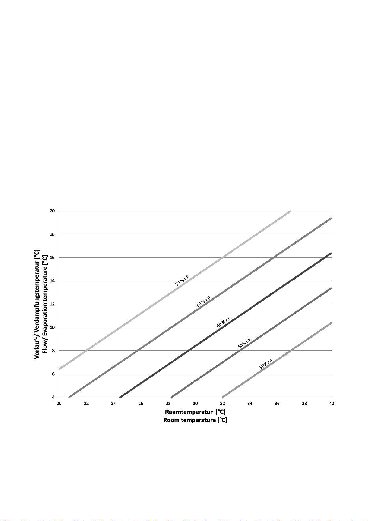
•Minimale Verdampfungstemperatur: 4 °C
Filtern:
•Von Raum- und Außenluft.
Zulässige Umgebungstemperaturen:
•3- 40 °C
Eigenschaften von Wasser/ wasserbasierten Solen:
pH- Wert: 6- 8
Sauerstoffgehalt: < 0,1 mg/l
Max. Wassertemperatur: 90 °C
Min. Wassertemperatur: 4 °C
Wasserhärte max. 14 °dH (2,5 mmol/l)
Maximal zulässige statische Pressung:
Folgende Werte sind maximal zulässig.
•HKN/D 10- 50 EC: 15 Pa
•HKN/D 200- 700: 50 Pa
•HKN/D 200- 700 EC: 50 Pa
•HKN/DL 800- 1400: 50 Pa
•HKN/DI 800- 1400: 50 Pa
•HKN/D/I/L 800- 1400 EC: 50 Pa
Bei zusätzlichem Gegendruck verändern sich die Schall- und
Luftleistungskennwerte sowie die Leistung.
•Die Montage und der Anschluss müssen nach dieser Anleitung
erfolgen.
Bestimmungswidrige Verwendung
•Der Gebläsekonvektor ist keine Sitzgelegenheit.
•Stellen Sie keine Gegenstände auf den Gebläsekonvektor.
•Der Gebläsekonvektor darf nicht im (teilweise)
demontierten Zustand betrieben werden.
Alle nicht bestimmungsgemäßen Verwendungen sind verboten!
7 Intended application
Application range:
•Operation with circulating air, outdoor air or mixed air.
•Functions: Ventilation, heating, cooling, dehumidifying and filtering
of room air.
•The fan coil unit may only be operated with technically
unobjectionable refrigeration or heating plant.
•The fan coil may not be run next to flammable materials or
components.
•The fan coil may not be run in explosive ambient.
•The fan coil mustn’t take over security relevant duties.
•Air inlet and air outlet mustn’t be covered by covers or other
structural arrangements.
•Max. operating pressure, operating voltage and power
consumption see type plate.
•Max. air blow out temperature 75°C (Danger of burning)!
•The following pollutions of the air have to be avoided:
➢Abrasive particles.
➢Strong corrosive pollutions e.g. salt spray mist.
➢High dust loading, e.g. exhaustion of saw dust.
➢Flammable gases/ particles.
Heating:
•With hot water and brines, optional electric heater.
Respect the fan speed limit if heating by electric heaters!
(See chapter electric booster heating.)
Cooling:
•By chilled water and brines or refrigerant.
•The unit is suitable for all refrigerants of safety group A1 according
to EN 378-1. These refrigerants are assigned to group 2 in the
Pressure Equipment Directive (PED).
•Allowable operating pressure PS see type plate.
•Minimal evaporation temperature: 4 °C
Filter:
•Filtering of room air and outdoor air.
Allowable ambient temperatures:
•3- 40 °C
Properties of water and water based brines:
pH- values: 6- 8
Oxygen content: < 0,1 mg/l
Max. water temperature: 90 °C
Min. water temperature: 4°C
Water hardness max. 14 °dH (2,5 mmol/l)
Maximum allowable static pressure:
The maxium allowable values are:
•HKN/D 10- 50 EC: 15 Pa
•HKN/D 200- 700: 50 Pa
•HKN/D 200- 700 EC: 50 Pa
•HKN/DL 800- 1400: 50 Pa
•HKN/DI 800- 1400: 50 Pa
•HKN/D/I/L 800- 1400 EC: 50 Pa
If the unit faces additional static pressure the air flow, the capacity
and the sound pressure level alter.
•Mounting and connection have to be done according to these
instructions.
Application not for intended purpose
•The fan coil unit is no seating.
•Don’t place objects on the fan coil.
•The fan coil unit mustn’t be operated in (partly)
demounted status.
Use for purpose other than designed for is forbidden!

7
8 Lagerung
•Anlage bis zur Montage trocken und wettergeschützt in sauberer
Umgebung in der Originalverpackung lagern. Wir empfehlen eine
maximale Lagerdauer von einem Jahr.
•Zulässige Umgebungstemperaturen: 1 °C bis 80 °C
Zwischenlagerung:
•Medien aus dem Wärmeaustauscher fachgerecht entfernen:
Kältemittelführende Wärmeaustauscher mit Stickstoff füllen und
luftdicht verschließen.
Wasserführende Wärmeaustauscher restlos entleeren, und mit
trockener, ölfreier Druckluft ausblasen.
•Gerät reinigen und in Originalverpackung einlagern.
8 Storage
•The unit has to be warehoused dry and weather protected in the
original packing until installation. We recommend a maximum
storage period of one year.
•Acceptable ambient temperatures: 1°C to 80 °C
Temporary storage:
•Remove the fluids professional from the heat exchanger:
Fill refrigerant heat exchangers with nitrogen and seal it air- tight.
Drain water heatexchangers completly and blow them completly dry.
•Purify the unit and store in original packiging.
9 Transport
•Zum Transport die Originalverpackung verwenden.
•Nur an den vorgesehenen Transportvorrichtungen mit geeignetem
Hebezeug transportieren. Gewichtangabe siehe Kapitel 12- 17.
•Anlage vorsichtig transportieren, Schläge und Stöße vermeiden.
9 Shipping
•Use the original packing for transport.
•The cooler should only be moved with intended lifting device using
appropriate fixtures. For weight specifications see chapter 12- 17.
•Move the unit carefully to avoid jolts and impacts.
10 Kondensatbildung an Gehäuseteilen
Bei bestimmten Umgebungsbedingungen kann Kondensatbildung an
Gehäuseteilen auftreten. Das nachfolgende Diagramm zeigt die
Grenzen ab derer eine Kondensatbildung möglich ist.
10 Condensate formation at housing
At certain ambient conditions condensate formation at housing
parts can’t be avoided. The following diagram, shows the limits
when condensate formation can occur.
Durch zusätzliche Isolierung der Gehäuseteile können die aus dem
Diagramm ermittelten Werte verschoben werden.
By additional insulation of the housing parts, the values given in the
diagram can be adjusted.

8
11 Materialien HKN
11 Materials HKN
Materialliste HKN
1. Grundgerät:
Stahlblech sendzimirverzinkt.
2. Wärmeaustauscher:
Kupferrohre Cu- DHP,
Aluminium- Lamellen EN- AW 8006, Kupferlamellen: Cu-DHP,
Goldlacklamellen.
3. Tropfschale:
Stahlblech sendzimirverzinkt, pulverbeschichtet, isoliert gegen
Kondensatbildung.
4. Querstromventilator (HKN/D 10- 50):
mit EC- Motor 230 V, 50/ 60 Hz, Walze: Aluminium.
Radialventilator (HKN/D 200- 1400)
Gehäuse aus PP,
Lüfterrad und Aufhängung aus PA.
230 V, 50/ 60 Hz
Thermokontakt, intern verdrahtet
Schutzart IP 44.
Sonderausführungen:
•Thermokontakt herausgeführt
•EC Ventilator
•Ventilator- und Gehäuse aus Blech
5. Luftfilter:
Trockenschichtfilter (HKN/D 10-50).
Güteklasse G3 nach EN 779 (HKN/D/I/L 200- 1400).
6. Anschlüsse Wärmeaustauscher:
Kupfer (Kältemittel) oder Messing (Wasser).
7. Seitliche Kondensatwanne
Wandausführung:
Ablaufstutzen R3/4″ aus PA. Material: Stahlblech sendzimirverzinkt,
pulverbeschichtet.
Deckenausführung: Kunststoff, Anschluss Cu 15x 1.
8. Elektrischer Schaltkasten:
Stahlblech, sendzimirverzinkt.
9. Anschlussdose:
Kasten: Polycarbonat, Membranen aus TPE
Deckel: Polystyrol
Schutzart IP 54.
Basic unit HKN
1. Basic unit:
Material: Hot- dip galvanized sheet steel.
2. Heat exchanger:
Copper tubes Cu- DHP,
Aluminum fins EN-AW 8006, Copper fins: Cu- DHP, prelacquered
fins.
3. Drain pan:
Hot- dip galvanized sheet steel, powder coated, insulated against
condensate formation.
4. Cross flow fan (HKN/D 10- 50):
with EC- Motor 230 V, 50/ 60 Hz, Cross flow fan wheel: Aluminum.
Radial fan (HKN/D 200- 1400):
Housing made of PP,
impeller and suspension made of PA.
230 V, 50/ 60 Hz
Internal wired thermal contact.
Protection class IP 44.
Special versions:
•External thermal contact
•EC fans
•Fans and housing made of sheet.
5. Air filter:
Dry- tape layer filter (HKN/D 10-50).
Filter class G3 according to EN 779 (HKN/D/I/L 200- 1400).
6. Connections of heat exchanger:
Copper (refrigerant) or brass (water).
7. Side condensate pan,
Wall version: Drain union R3/4″ made of PA.
Material: Hot- dip galvanized sheet steel, powder coated.
Ceiling version: Plastics, connection Cu 15x1.
8. Control box:
Hot- dip galvanized sheet steel.
9. Terminal box:
Made of Polycarbonat, membrans of TPE, cover of Polystyrol.
Protection class IP54.

9
12 Grundgerät HKN 10- 50 EC
Abmessungen, elektrische Anschlusswerte,
Gewichte, Schalldruckpegel
12 Basic unit HKN 10- 50 EC
Dimensions, electric loads, weights, sound
pressure levels
13 Grundgerät HKND 10- 50 EC
Abmessungen, elektrische Anschlusswerte,
Gewichte, Schalldruckpegel
13 Basic unit HKND 10- 50 EC
Dimensions, electric loads, weights, sound
pressure levels
Grundgerät
Abmessungen in mm
EC Querstromgebläse ~ 220- 240 V, 50/ 60 Hz
Gewicht
Rohrinhalt
Schalldruck
Basic unit
Dimensions in mm
EC cross fan blower ~ 220- 240 V, 50/ 60 Hz
Weight
Tube volume
Sound pressure
Anzahl
Leistung
Stromaufn.
Drehzahl
2 Leiter
4 Leiter
WT1
WT2
Number
Input cap.
Curr. Cons.
r.p.m.
2 lines
4 lines
HX1
HX2
HKN/D
A
B
C
W
A
min-1
kg
kg
dm³
dB(A)
10
580
445
430
1
38
0,32
1500
15
16
0,7
0,2
22- 45
20
780
645
630
1
38
0,32
1500
18
19
1,1
0,4
23- 46
30
980
845
830
1
38
0,32
1500
19
21
1,4
0,5
24- 47
40
1180
1045
1030
1
38
0,32
1500
23
25
1,8
0,6
24- 48
50
1380
1245
1230
1
38
0,32
1500
26
28
2,1
0,7
25- 50
Schalldruckpegel in 1 m Abstand (Grundgerät mit Filter und Gehäuse)
Sound pressure levels at a distance of 1 m (Basic unit with air filter and housing)
WT1
HX 1
WT2
HX 2
WT 1
HX 1
WT2
HX 2

10
14 Grundgerät HKN 200- 700 (EC)
Abmessungen, elektrische Anschlusswerte,
Gewichte, Schalldruckpegel
14 Basic unit HKN 200- 700 (EC)
Dimensions, electric loads, weights, sound
pressure levels
Grundgerät
Abmessungen in mm
Gewicht
Rohrinhalt
Schalldruck
Basic unit
Dimensions in mm
Weight
Tube volume
Sound pressure
2 Leiter
2 lines
4 Leiter
4 lines
Kühlen
Cooling
Heizen
Heating
HKN
A
B
C
D
kg
dm³
dB(A)
200
870
660
640
470
26
1,4
1,1
0,7
18 - 46
400
1 170
960
940
770
32
2,1
1,6
1,1
19 - 47
600
1 470
1 260
1 240
1 070
38
2,6
2,1
1,4
18 - 46
700
1 470
1 260
1 240
1 070
41
2,6
2,1
1,4
23 - 50
Schalldruckpegel in 1 m Abstand (Grundgerät mit Filter und Gehäuse)
Sound pressure levels at a distance of 1 m (Basic unit with air filter and housing)
AC- Radialgebläse ~ 230 V, 50/ 60 Hz
EC- Radialgebläse ~ 230 V, 50/ 60 Hz
AC- Radial blower ~ 230 V, 50/ 60 Hz
EC- Radial blower ~ 230 V, 50/ 60 Hz
Anzahl
Leistung
Stromaufn.
Drehzahl
Anzahl
Leistung
Stromaufn.
Drehzahl
Number
Input cap.
Curr. Cons.
r.p.m.
Number
Input cap.
Curr. Cons.
r.p.m.
W
A
min-1
W
A
min-1
1
65/ 68
0,29/ 0,30
780/ 710
1
100
0,8
1330
1*
85/ 100
0,38/ 0,44
750/ 760
1*
60
0,5
910
1*
85/ 100
0,38/ 0,44
750/ 760
1*
60
0,5
910
2**
150/ 168
0,67/ 0,74
750/ 760
2
200
1,6
1330
* Doppel- Radialgebläse ** 1 Doppel- Radialgebläse + 1 Einzel- Radialgebläse
* Dual radial blower unit ** 1 Dual radial blower unit + 1 single radial blower

11
15 Grundgerät HKND 200- 700 (EC)
Abmessungen, elektrische Anschlusswerte,
Gewichte, Schalldruckpegel
15 Basic unit HKND 200- 700 (EC)
Dimensions, electric loads, weights, sound
pressure levels
Grundgerät
Abmessungen in mm
Gewicht
Rohrinhalt
Schalldruck
Basic unit
Dimensions in mm
Weight
Tube volume
Sound pressure
2 Leiter
2 lines
4 Leiter
4 lines
Kühlen
Cooling
Heizen
Heating
HKND
A
B
C
D
kg
dm³
dB(A)
200
870
660
640
470
26
1,4
1,1
0,7
18 - 46
400
1 170
960
940
770
32
2,1
1,6
1,1
19 - 47
600
1 470
1 260
1 240
1 070
38
2,6
2,1
1,4
18 - 46
700
1 470
1 260
1 240
1 070
41
2,6
2,1
1,4
23 - 50
Schalldruckpegel in 1 m Abstand (Grundgerät mit Filter und Gehäuse)
Sound pressure levels at a distance of 1 m (Basic unit with air filter and housing)
Grundgerät
AC- Radialgebläse ~ 230 V, 50/ 60 Hz
EC- Radialgebläse ~ 230 V, 50/ 60 Hz
Basic unit
AC- Radial blower ~ 230 V, 50/ 60 Hz
EC- Radial blower ~ 230 V, 50/ 60 Hz
Anzahl
Leistung
Stromaufn.
Drehzahl
Anzahl
Leistung
Stromaufn.
Drehzahl
Number
Input cap.
Curr. Cons.
r.p.m.
Number
Input cap.
Curr. Cons.
r.p.m.
HKND
W
A
min-1
W
A
min-1
200
1
65/ 68
0,29/ 0,30
780/ 710
1
100
0,8
1330
400
1*
85/ 100
0,38/ 0,44
750/ 760
1*
60
0,5
910
600
1*
85/ 100
0,38/ 0,44
750/ 760
1*
60
0,5
910
700
2**
150/ 168
0,67/ 0,74
750/ 760
2
200
1,6
1330
* Doppel- Radialgebläse ** 1 Doppel- Radialgebläse + 1 Einzel- Radialgebläse
* Dual radial blower unit ** 1 Dual radial blower unit + 1 single radial blower

12
16 Grundgerät HKN/I/L 800- 1400 (EC)
Abmessungen, elektrische Anschlusswerte,
Gewichte, Schalldruckpegel
16 Basic unit HKN/I/L 800- 1400 (EC)
Dimensions, electric loads, weights, sound
pressure levels
Grundgerät
Abmessungen in mm
Gewicht
Rohrinhalte
Schall-druck
Basic unit
Dimensions in mm
Weight
Tube volume
Sound pressure
2 Leiter
2 lines
4 Leiter
4 lines
DV
W
Kühlen
Cooling
Heizen
Heating
HKNI
A
B
C
D
E
kg
dm³
dB(A)
800
1570
1340
1200
1260
1383
53
3,9
3,9
2,9
1,5
32 - 52
1000
1870
1640
1500
1560
1683
64
4,7
5,3
3,5
1,8
33 - 53
1200
2170
1940
1800
1860
1983
75
5,5
6,2
4,1
2,1
35 - 55
1400
2670
2440
2300
2360
2483
90
6,8
7,7
5,1
2,6
36 - 56
HKNL
800
1570
1340
1200
1260
1383
53
3,9
3,9
2,9
1,5
20 - 45
1000
1870
1640
1500
1560
1683
64
4,7
5,3
3,5
1,8
23 - 48
1200
2170
1940
1800
1860
1983
75
5,5
6,2
4,1
2,1
24 - 49
1400
2670
2440
2300
2360
2483
90
6,8
7,7
5,1
2,6
25 - 50
Schalldruckpegel in 1 m Abstand (Grundgerät mit Filter und Gehäuse)
Sound pressure levels at a distance of 1 m (Basic unit with air filter and housing)
Grundgerät
AC- I- Gebläse ~ 230 V, 50/ 60 Hz
AC- L- Gebläse 230 V, 50/ 60 Hz
EC- Gebläse 230 V, 50/ 60 Hz
Basic unit
AC- I- Blower ~ 230 V, 50/ 60 Hz
AC- L- Blower 230 V, 50/ 60 Hz
EC- Blower 230 V, 50/ 60 Hz
Anzahl
Leistung
Stromaufn.
Drehzahl
Leistung
Stromaufn.
Drehzahl
Leistung
Stromaufn.
Drehzahl
Number
Input cap.
Curr. cons.
r.p.m.
Input cap.
Curr cons.
r.p.m.
Input cap.
Curr cons.
r.p.m.
HKN
W
A
min-1
W
A
min-1
W
A
min-1
800
2
180/ 230
0,80/ 1,02
1330/ 1510
130/ 136
0,58/ 0,60
780/ 710
200
1,6
1330
1000
3
270/ 345
1,20/ 1,53
1330/ 1510
195/ 204
0,87/ 0,90
780/ 710
300
2,4
1330
1200
4
360/ 460
1,60/ 2,04
1330/ 1510
260/ 272
1,17/ 1,20
780/ 710
400
3,2
1330
1400
5
450/ 575
2,00/ 2,55
1330/ 1510
325/ 340
1,45/ 1,50
780/ 710
500
4,0
1330

13
17 Grundgerät HKNDI/L 800- 1400 (EC)
Abmessungen, elektrische Anschlusswerte,
Gewichte, Schalldruckpegel
17 Basic unit HKNDI/L 800- 1400 (EC)
Dimensions, electric loads, weights, sound
pressure levels
Grundgerät
Abmessungen in mm
Gewicht
Rohrinhalte
Schalldruck
Basic unit
Dimensions in mm
Weight
Tube volume
Sound pressure
2 Leiter
2 lines
4 Leiter
4 lines
DV
W
Kühlen
Cooling
Heizen
Heating
HKNDI
A
B
C
D
E
kg
dm³
dB(A)
800
1570
1383
1345
1200
603
61
3,9
3,9
2,9
1,5
32 - 52
1000
1870
1683
1645
1500
753
73
4,7
5,3
3,5
1,8
33 - 53
1200
2170
1983
1945
1800
903
85
5,5
6,2
4,1
2,1
35 - 55
1400
2670
2483
2445
2300
1153
103
6,8
7,7
5,1
2,6
36 - 56
HKNDL
800
1570
1340
1200
1260
603
61
3,9
3,9
2,9
1,5
20 - 45
1000
1870
1640
1500
1560
753
73
4,7
5,3
3,5
1,8
23 - 48
1200
2170
1940
1800
1860
903
85
5,5
6,2
4,1
2,1
24 - 49
1400
2670
2440
2300
2360
1153
103
6,8
7,7
5,1
2,6
25 - 50
Grundgerät
AC- I- Gebläse ~ 230 V, 50/ 60 Hz
AC- L- Gebläse 230 V, 50/ 60 Hz
EC- Gebläse 230 V, 50/ 60 Hz
Basic unit
AC- I- Blower ~ 230 V, 50/ 60 Hz
AC- L- Blower 230 V, 50/ 60 Hz
EC- Blower 230 V, 50/ 60 Hz
Anzahl
Leistung
Stromaufn.
Drehzahl
Leistung
Stromaufn.
Drehzahl
Leistung
Stromaufn.
Drehzahl
Number
Input cap.
Curr. cons.
r.p.m.
Input cap.
Curr cons.
r.p.m.
Input cap.
Curr cons.
r.p.m.
HKND
W
A
min-1
W
A
min-1
W
A
min-1
800
2
180/ 230
0,80/ 1,02
1330/ 1510
130/ 136
0,58/ 0,60
780/ 710
200
1,6
1330
1000
3
270/ 345
1,20/ 1,53
1330/ 1510
195/ 204
0,87/ 0,90
780/ 710
300
2,4
1330
1200
4
360/ 460
1,60/ 2,04
1330/ 1510
260/ 272
1,17/ 1,20
780/ 710
400
3,2
1330
1400
5
450/ 575
2,00/ 2,55
1330/ 1510
325/ 340
1,45/ 1,50
780/ 710
500
4,0
1330

14
18 Montage Standgerät
•Die Anlage darf nur von autorisiertem Fachpersonal montiert
werden.
•Vorsicht an Wänden und Decken in denen Strom-, Gas- und/ oder
Wasserleitungen verlegt sein können.
•Zur Befestigung werden Schrauben M8 Festigkeitsklasse 8.8
empfohlen. Befestigungsmaterialien entsprechend Gerätegewicht
und baulichen Gegebenheiten auswählen.
•Die Bohrskizzen auf den nachfolgenden Seiten beachten. Bei der
Montage alle Befestigungspunkte verwenden.
•Bei der Montage des Gerätes Sicherheitsschuhe und
Schutzhandschuhe tragen.
1. Auspacken. Gerät auf Beschädigungen überprüfen. Beschädigte
Geräte dürfen nicht montiert werden.
2. Befestigungen vorbereiten. Bohrskizzen siehe nächste Seiten.
3. Das Gerät an den Schlüssellöchern einhängen. Schrauben
anziehen (Anziehmoment: 9 Nm).
4. Waagrechte und senkrechte Ausrichtung der Geräte überprüfen
und ggf. korrigieren.
Bei verdeckter Installation (z.B. hinter einer Brüstung) des
Klimagerätes ist folgendes zu beachten:
•Revisionsöffnungen für Filterwechsel und zur Reinigung der
Kondenswasser führenden Teile vorsehen.
18 Installation of standing unit
•The unit may only be installed by authorized and skilled
personnel.
•Be careful at walls and ceilings that could contain electric wires,
gas and water piping.
•For fixation we recommend screws M8 property class 8.8.
Dimension anchors according to unit weight and construction
materials.
•Obey the drilling patterns on the following pages. When mounting
use all anchor points.
•When mounting the unit use protective shoes and gloves.
1. Unpack. Check the unit for damages. Damaged units mustn’t be
mounted.
2. Prepare anchors. Drilling drafts on following pages.
3. Hinge the unit at the keyholes. Tighten screws (Torque: 9 Nm).
4. Check the level of the units and correct if necessary.
If the fan coil is hidden the following points have to be obeyed:
•Plan inspection openings for exchange of the filter as well as
cleaning purposes of the condensate- bearing parts.
1.
2.
3.
4.

15
19 Montage Deckengerät
•Die Anlage darf nur von autorisiertem Fachpersonal montiert
werden.
•Vorsicht an Wänden und Decken in denen Strom-, Gas- und/ oder
Wasserleitungen verlegt sein können.
•Zur Befestigung werden Schrauben M8 Festigkeitsklasse 8.8
empfohlen. Befestigungsmaterialien entsprechend Gerätegewicht
und baulichen Gegebenheiten auswählen.
•Verwenden Sie schwingungsdämpfende Elemente bei der Montage.
•Die Bohrskizzen auf den nachfolgenden Seiten beachten. Bei der
Montage alle Befestigungspunkte verwenden.
•Bei der Montage des Gerätes Sicherheitsschuhe, Kopfschutz und
Schutzhandschuhe tragen.
•Die Montage eines Deckengerätes immer mindestens zu Zweit
durchführen.
•Sperren Sie den Montagebereich weiträumig ab.
1. Auspacken. Gerät auf Beschädigungen überprüfen. Beschädigte
Geräte dürfen nicht montiert werden.
2. Befestigungen vorbereiten. Bohrskizzen siehe nächste Seiten.
3. Das Gerät mit einem Hubwagen, Gabelstapler o.Ä. auf das Niveau
der Befestigungen anheben.
4. Das Gerät an den Schlüssellöchern einhängen. Schrauben
anziehen (Anziehmoment: 9 Nm).
5. Waagrechte Ausrichtung der Geräte überprüfen und ggf.
korrigieren.
Bei verdeckter Installation (z.B. Zwischendecke) des Klimagerätes ist
folgendes zu beachten:
•Revisionsöffnungen für Filterwechsel und zur Reinigung der
Kondenswasser führenden Teile vorsehen.
•Zeichnungen und Hinweise für Übergangsstücke z.B.
Segeltuchstutzen s. Kapitel Anschlussmaße.
19 Installation of ceiling unit
•The unit may only be installed by authorized and skilled
personnel.
•Be careful at walls and ceilings that could contain electric wires,
gas and water piping.
•For fixation we recommend screws M8 property class 8.8.
Dimension anchors according to unit weight and construction
materials.
•Use dampers when mounting.
•Obey the drilling patterns on the following pages. When mounting
use all anchor points.
•When mounting the unit use protective shoes and gloves.
•Execute the mounting with at least two persons.
•Close off the mounting area.
1. Unpack. Check the unit for damages. Damaged units mustn’t be
mounted.
2. Prepare anchors. Drilling drafts on following pages.
3. Lift the unit by means of a fork lift or similar to the level of the
anchors.
4. Hinge the unit at the keyholes. Tighten screws (Torque: 9 Nm).
5. Check the level of the units and correct if necessary.
If the fan coil is hidden (e.g. suspended ceiling) the following points
have to be obeyed:
•Plan inspection openings for exchange of the filter as well as
cleaning purposes of the condensate- bearing parts.
•Drawings and notices for adapters e.g. canvas connection see
chapter connection measurements.
1.
2.
3.
4.
5.

16
20 Bohrskizze HKN/D 10- 50 EC
20 Drilling draft HKN/D 10- 50 EC
Grundgerät
Abmessungen in mm
Basic unit
Dimensions in mm
HKN/D
A
B
10
580
445
20
780
645
30
980
845
40
1180
1045
50
1380
1245
21 Bohrskizze HKN/D 200- 700 (EC)
21 Drilling draft HKN/ D 200- 700 (EC)
Grundgerät
Abmessungen in mm
Basic unit
Dimensions in mm
HKN/D
A
B
200
870
660
400
1 170
960
600
1 470
1 260
700
1 470
1 260

17
22 Bohrskizze HKN/ I/ L 800- 1400 (EC)
22 Drilling draft HKN/ I/ L 800- 1400 (EC)
Grundgerät
Abmessungen in mm
Basic unit
Dimensions in mm
HKNDL/I
A
B
800
1570
1340
1000
1870
1640
1200
2170
1940
1400
2670
2440
23 Bohrskizze HKND/ I/ L 800- 1400 (EC)
23 Drilling draft HKND/ I/ L 800- 1400 (EC)
Grundgerät
Abmessungen in mm
Basic unit
Dimensions in mm
HKNDL/I
A
B
C
800
1570
1383
603
1000
1870
1683
753
1200
2170
1983
903
1400
2670
2483
1153

18
24 Umbau Stand- zu Deckengerät
(HKN 10- 50 EC)
Das HKN 10- 50 EC kann mit wenigen Handgriffen von der Stand auf
die Deckenversion umgebaut werden.
Die dafür notwendigen Komponenten sind separat erhältlich.
Beachten Sie bei der Verwendung von Kondensatpumpen Kapitel 28.
1. Befestigungsschrauben der Tropfschale (Stand) lösen.
2. Tropfschale (Stand) abnehmen, Kunstoffrohrbogen abnehmen.
3. Tropfschale (Decke) auf Abfluss des Tropfbleches schieben,
Dichtung kontrollieren.
4. Tropfschale (Decke) montieren, und weiterführende
Kondensatableitung sicherstellen.
24 Retrofit floor to ceiling mounted unit
(HKN 10- 50 EC)
HKN 10- 50 EC can be retrofitted from floor to ceiling mounted unit
with only a few handles.
The needed components are available on request.
If using condensate pumps, pay attention to chapter 28.
1. Loose fixation screws of the drain pan (floor).
2. Dismantle drain pan (floor) and plastic bend tube.
3. Mount drain pan (ceiling) to the drain of the drain sheet, check
the seal.
4. Screw Drain pan (ceiling) Tropfschale, ensure further
condensate drain.
25 Hydraulischer Anschluss
Wärmetauscher Kältemittel
Die gültigen technischen Vorschriften d.h. Normen, Richtlinien und
Regelwerke sind einzuhalten.
•Die Variante des Wärmeaustauschers beachten.
1. Verschlusskappen vom Wärmeaustauscher abnehmen.
2. Montieren Sie Ventile entsprechend deren Montageanleitung.
3. Den Wärmeaustauscher an das vorhandene Kältemittelnetzwerk
anschließen. Die Lage der Anschlüsse ist auf den folgenden Seiten
ersichtlich.
4. Der Anschluss muss mechanisch spannungsfrei ausgeführt sein.
5. Rohrleitungen isolieren.
6. Druck- und Dichtheitsprüfung entsprechend den gültigen
Regelwerken durchführen.
25 Hydraulic installation heat exchanger
refrigerant
Relevant technical advices like rules and standards have to be
obeyed.
•Pay attention to the variant of the heat exchangers.
1. Remove end caps of the heat exchanger.
2. Pay attention to the mounting instructions of the valves and
mount them according to these explanations.
3. Connect the heat exchanger to the existing refrigerant supply.
The layout of the connections can be found on the following pages.
4. The connection has to be done unstressed,
5. The piping has to be insulated.
6. Perfom pressure and leak-tightness according to the rules and
standards in force.
3. / 4.
1./ 2.

19
26 Hydraulischer Anschluss
Wärmetauscher Wasser
Die gültigen technischen Vorschriften d.h. Normen, Richtlinien und
Regelwerke sind einzuhalten.
•Die Variante des Wärmeaustauschers beachten.
•Ggf. Verschlusskappen vom Wärmeaustauscher abnehmen.
1. Montieren Sie Ventile entsprechend deren Montageanleitungen
und beachten Sie die nachfolgenden Skizzen.
Vormontierte Ventile sind nicht auf Dichtheit getestet.
2. Den Wärmeaustauscher an das vorhandene Heizung/-
Kaltwasser- netz anschließen. Die Lage der Anschlüsse ist auf den
Seiten 21- 26 ersichtlich.
3. Der Anschluss muss mechanisch spannungsfrei ausgeführt sein.
4. Rohrleitungen für Kühlmedien isolieren.
5. Druck- und Dichtheitsprüfung entsprechend den gültigen
Regelwerken durchführen.
6. Vor der Inbetriebnahme die Wärmeaustauscher über die
Entlüftungsventile entlüften.
26 Hydraulic connection heat exchanger
water
Relevant technical advices like rules and standards have to be
obeyed.
•Pay attention to the variant of the heat exchangers.
•If applicable remove end caps of the heat exchanger.
1. Pay attention to the mounting instructions of the valves and
mount them according to these explanations.
Premounted valves aren’t tested for leak- tightness.
2. Connect the heat exchanger to the existing hot respectively cold
water supply. The layout of the connections can be found on the
pages 21-26.
3. The connection has to be done unstressed,
4. The piping of cooling agents has to be insulated.
5. Perfom pressure and leak-tightness according to the rules and
standards in force.
6. Before setting the fan coil in operation, bleed the heat
exchangers.
Anschluss Durchgangsventil HKN/D 10- 700 Anschluss Durchgangsventil HKN/D 800- 1400
Connection straight- through valve HKN/D 10- 700 Connection straight- through valve HKN/D 800- 1400
Anschluss 3- Wege Ventil HKN/D 10- 700 Anschluss 3- Wege Ventil HKN/D 800- 1400
Connection 3- way valve HKN/D 10- 700 Connection 3- way valve HKN/D 800- 1400

20
27 Kondensatablauf
Das Gerät ist waagrecht zu installieren um einen korrekten
Kondensatablauf im Inneren sicherzustellen.
1. Den Kondensatablauf mit Gefälle ausführen. Anschlussmaße
siehe folgende Seiten. Ist dies nicht möglich, eine Kondensatpumpe
einsetzen.
2. Beachten Sie bei dem Anschluss an die Kanalisation die örtlichen
Vorschriften für die Einleitung von Kondensaten. Sehen Sie ein
Siphon und eine Rückschlagsicherung vor.
3. Den Kondensatablauf auf Dichtheit und Funktion testen.
27 Condensate drain
The unit has to be leveled out to ensure a correct
condensate drain.
1. Install the condensate drainage with a downward gradient. See
the following pages for the connection layout. If this isn’t possible
use a condensate pump.
2. Install a siphon as well as a nonreturn finger and pay attention to
the local rules and standards for discharging condensates.
3. Check condensate drainage for function and tightness.
Beispiel: Kondensatablauf am Deckengerät. Beispiel: Kondensatablauf am Standgerät.
Example: Condensate drain at ceiling unit. Exampke: Condensate drain at ceiling unit.
28 Kondensatpumpe
Die Kondensatpumpe ist am Fuß der Tropfschale montiert.
Auch bei ausgeschaltetem Gerät kann Kondensat anfallen. Stellen
Sie sicher, dass die Kondensatpumpe auch bei ausgeschaltetem
Gerät funktioniert.
Im Falle einer Nachrüstung sind die folgenden Schritte zu
absolvieren:
1. Die Pumpe an das Seitenteil schrauben.
2. Den Schwimmerschalter am tiefst- möglichen Punkt anbringen.
3. Schwimmerschalter mit Pumpe verbinden.
Folgende Schritte müssen immer durchgeführt werden.
4. Der elektrische Anschluss der Pumpe ist bauseits durchzuführen.
5. Die Montageanleitung der Kondensatpumpe beachten.
28 Condensate pump
The condensate pump is mounted near the drain pan at the stand.
Even if the unit is switched off condensate may occur. Ensure that
the condensate pump is working when the unit is switched off.
In case of retro- fit of the condensate pump, do the following steps:
1. Screw the pump to the stand.
2. Mount the floating switch at the lowest possible point.
3. Connect the floating switch to the pump.
The following steps have to be done always.
4. The electric connection has to be sold on site.
5. Pay attention to the mounting instructions of the condensate
pump.
This manual suits for next models
2
Table of contents
Popular Air Conditioner Accessories manuals by other brands

Klarstein
Klarstein WINDOW KIT 2 manual

Daikin
Daikin DZK Series installation manual

GE
GE RAB46 installation instructions

Hotpoint
Hotpoint RAB80 installation instructions

Unitary products group
Unitary products group 2CE Series installation instructions

Waeco
Waeco AirConServiceCenter ASC 3500 G LE operating manual