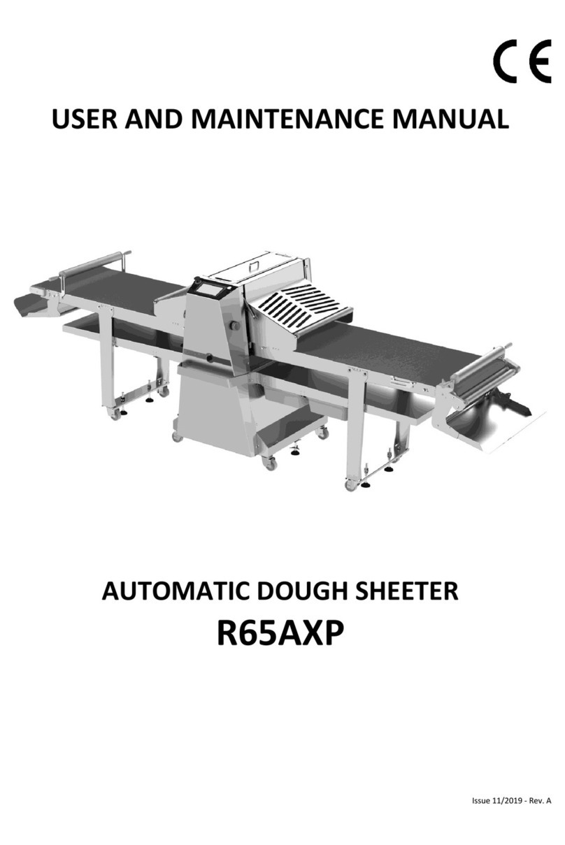
Rollmatic R62 Operating instructions

USER AND MAINTENANCE MANUAL
DOUGH SHEETER
R62 – R62T
R65 – R65T
Edition 01/2015 - Rev. A

2
R62 / R62T / R65 / R65T - Rev. A
TABLE OF CONTENTS
1 INTRODUCTION .................................................................................................................................. 3
1.1 FOREWORD ................................................................................................................................................. 3
1.2 GENERAL INSTRU TIONS AND WARNINGS ................................................................................................ 4
1.3 MAIN ASES FOR WHI H THE OMPANY DE LINES ANY RESPONSIBILITY ................................................ 5
1.4 TERMINOLOGY ............................................................................................................................................ 5
2 MACHINE FEATURES ........................................................................................................................... 6
2.1 INTENDED USE AND DES RIPTION ............................................................................................................. 6
2.2 TE HNI AL FEATURES ................................................................................................................................ 9
2.3 OVERALL DIMENSIONS ............................................................................................................................. 10
2.4 ONTROL AND ADJUSTMENT DEVI ES .................................................................................................... 11
2.5 IDENTIFI ATION PLATE ............................................................................................................................. 11
3 INSTALLATION AND USE .................................................................................................................... 12
3.1 WARNINGS ON INSTALLATION SITE ......................................................................................................... 12
3.2 INSTRU TIONS FOR LIFTING, TRANSPORT AND POSITIONING OPERATIONS .......................................... 12
3.3 ELE TRI AL ONNE TION ........................................................................................................................ 13
3.4 OPERATION AND USE ............................................................................................................................... 13
3.4.1 PRE AUTIONS AND PRELIMINARY HE KS .....................................................................................14
3.4.2 GENERAL INFORMATION ON NORMAL OPERATION .......................................................................14
3.4.3 STARTING AND OPERATION .............................................................................................................14
3.4.4 OPERATING AND USING THE MA HINE...........................................................................................14
3.4.5 DOUGH THI KNESS ADJUSTMENT ...................................................................................................15
3.4.6 FLOUR OLLE TION DRAWER ..........................................................................................................15
3.4.7 ASSEMBLING AND DISASSEMBLING THE WORK TABLES .................................................................16
3.4.8 UTTING STATION............................................................................................................................17
3.4.9 FLOUR DUSTER .................................................................................................................................18
3.4.10 DOUGH REELER ................................................................................................................................19
4 MAINTENANCE ................................................................................................................................. 20
4.1 FOREWORD ............................................................................................................................................... 20
4.2 PERIODI AL MAINTENAN E (ordinary maintenance) .............................................................................. 20
4.3 BELT TENSION ........................................................................................................................................... 20
4.4 HAIN TENSION (extraordinary maintenance) ......................................................................................... 21
4.5 HAIN REPLA EMENT (extraordinary maintenance) ............................................................................... 21
4.6 HANDLE LUBRI ATION (extraordinary maintenance) .............................................................................. 22
4.7 INTERVENTIONS TO BE ARRIED OUT EX LUSIVELY BY AUTHORIZED ENGINEERS ................................. 22
4.8 POSSIBLE FAILURES AND/OR FAULTS ....................................................................................................... 23
4.9 ELE TRI AL MAINTENAN E ..................................................................................................................... 24
4.10 LEANING THE MA HINE ......................................................................................................................... 24
4.10.1 LEANING THE BELTS AND THE WORK TABLES ...............................................................................25
4.10.2 REPLA ING THE BELTS .....................................................................................................................25
4.10.3 LEANING THE S RAPERS ................................................................................................................26
4.10LONG STOPS OR SERVI E DIS ONTINUATION ........................................................................................... 27
5 SAFETY ............................................................................................................................................. 27
5.1 FOREWORD ............................................................................................................................................... 27
5.2 HAZARDS, SAFETY DEVI ES AND RESIDUAL RISKS .................................................................................... 27
5.2.1 DANGERS AND ORRESPONDING RISKS THAT HARA TERIZE THE MA HINE ...............................27
5.2.2 SAFETY DEVI ES AND REMARKS ......................................................................................................28
5.2.3 HE KING THE EFFI IEN Y OF THE SAFETY EQUIPMENT ................................................................29
5.2.4 RESIDUAL RISKS OF ELE TRI AL ORIGIN ..........................................................................................29
5.2.5 RESIDUAL RISKS OF ELE TRI AL ORIGIN ..........................................................................................29
5.3 INFORMATION ON NOISE ......................................................................................................................... 30
5.4 SAFETY SIGNS ............................................................................................................................................ 30
6 DISMANTLING ................................................................................................................................... 31

R62 / R62T / R65 / R65T - Rev. A 3
1INTRODUCTION
1.1 FOREWORD
Th s user and ma ntenance manual s to be consulted by anyone who may be appo nted to,
charged w th and author zed to use the mach ne; the term "use" refers to any phase of the
machine's working cycle (from assembly and transport to maintenance operation to dismantling). It
s also ntended for the employer, the managers and any off cer of the company that w ll use the
mach ne: they will have to read it thoroughly and understand it fully so as to use it when complying
with part of the obligations on health and safety in the workplace. The employer, at whose plants
the machine is operating, as well as the managers and any officer within the company, must provide
any operators with suitable training and information (all information must be simple and
comprehensible, according to the foresight which can be reasonably expected of the intended
recipient) on its correct and safe use as well as on general and specific risks in the workplace and/or
inherent to the job itself. This manual can assist in such important task even though, for obvious
reasons, it cannot be considered as fully exhaustive as it is not strictly inherent to the actual
machine.
The manual cons sts n a number of sect ons, each of which has its specific purpose, and in
particular:
2 Mach ne features
3 Installat on and Use
3.4.10 Ma ntenance
5 Safety
6 D smantl ng
The word mach ne will hereafter indicate the item to be used by the purchaser and for which this
manual is written and given to the purchaser, so that he may use it in a correct and safe manner.
Before carrying out any operation on the machine (transport, installation, connections to utilities,
adjustments, operation, repair work, part replacement, dismantling, etc.) as well as before allowing
anyone to use the machine, usually laymen, carefully read the general and specific instructions
contained in this manual and ensure that its purposes and meaning are clear, so as to acquire the
necessary knowledge to correctly operate and maintain the machine, as well as to understand and
become familiar with the safety devices it is provided with, and finally the residual risks it presents,
and therefore to use it in a correct and safe manner.
Keep this manual and any attached document in a safe place (drawings, diagrams, etc.).
Should the manual be lost or worn out mmed ately request a copy to the manufacturer clearly
stating the identification details of the machine (year of construction, model, serial number, etc.).
This manual reflects the state of the art at the time the machine is launched into the market or
started up, and cannot be considered unsuitable just because it has been subsequently updated
following newly acquired experience or new technical solutions.
The manufacturer is not responsible for the suitability of the place where the machine is used nor for
any complementary service, regardless of the fact that instructions on correct installation are given
herein. The company reserves the right to update machines and manuals, but is not obliged to
update machines and/or manuals previously manufactured/drawn up.
Th s manual s an ntegral part of the mach ne and must accompany t should it be transferred or
sold for whatever reason, even for free.

4
R62 / R62T / R65 / R65T - Rev. A
ATTENTION! Before start up and operat on ensure that the mach ne s compl ant w th the
purchas ng order and complete w th all the dev ces descr bed n th s manual and n any
commerc al documentat on, espec ally any safety dev ces.
ATTENTION! The mach ne descr bed n th s manual s for produc ng sheets from bread, pastry and
p zza dough by mak ng the dough go through cal brat ng cyl nders that feature alternat ng
forward and backward movement. Th s mach ne cannot be used for any purposes other than
those descr bed above.
The manufacturing company will not be held responsible for any damage to properties and/or injury
to people or animals due to an incorrect use of the machine.
1.2 GENERAL INSTRUCTIONS AND WARNINGS
The manufacturing company declines any responsibility for damages to people, animals or
properties caused by failure to comply with the instructions contained in this manual and by the
failure to comply with the following indications:
•Do not tamper w th the guards and safety devices installed in the machine
•Repos t on all the protections and reset all the safety devices as soon as the reason why they
were removed/disabled is resolved
•Do not use the machine for purposes and/or with loads and/or in a way that does not correspond
to that indicated by the manufacturer
•Only use bread, pastry and pizza dough
•Carry out daily checks on safety devices, level and state of technical fluids, if present, in addition
to checks on the general state of the machine
•arefully clean the machine on a daily basis
•Adopt the necessary measures and precautions when carrying out adjustments, cleaning and
maintenance operations, etc. so that the machine or its components cannot be started by other
people, not even by accident
•The locat on where the mach ne s to be nstalled must comply w th European D rect ves as well
as w th the laws and regulat ons n force n the country where the mach ne s nstalled and used
•Respect any l m t regard ng cl mate cond t ons (see paragraph 2.2
TE HNI AL FEATURES
) and
permitted use
•The employer, at whose production sites the machine is installed, must guarantee that operators
are suitably informed and trained on their specific tasks, on safe and correct use of the machine
and on general and specific risks in the workplace and/or job-related this manual can be a useful
support tool but cannot be considered exhaustive
•Any manager who allows th rd part es to use the mach ne (for example the employer, and so
forth) must ensure that the machine is in good conditions, whole and fully functioning, especially
as regards safety equipment; should this not be the case, he must not allow it to be used and
must therefore put it out of service
•During maintenance and cleaning operations (and any other such operation) operators must
wear snug clothes free of loose parts; they may not wear aprons, jackets, unbuttoned shirts, etc.
nor are they allowed to wear jewels (bracelets, necklaces, etc.) that may unhook or become
entangled in protruding parts; should they have long hair, they must use hairnets.
•Should it be necessary to replace any parts, use or g nal spare parts only by ordering them from
the manufacturing company; should non-original spare parts be used, the manufacturing
company relieves itself of any and all responsibilities for any resulting damages to people,
properties and/or animals
•Any arb trary mod f cat on to the mach ne, rel eves the manufacturer of any and all
respons b l ty for any result ng damages to people, an mals and/or th ngs

R62 / R62T / R65 / R65T - Rev. A 5
1.3 MAIN CASES FOR WHICH THE COMPANY DECLINES ANY RESPONSIBILITY
The manufacturing company declines any responsibility for damages to people, animals and
properties as well as for missed production due to:
•Use of the mach ne not n compl ance with the intended use or with products different from
those expressly declared in this manual
•Installat on not n compl ance with the procedures illustrated in this manual
•Use of the mach ne by nadequately nformed personnel and, where foreseen, inadequately
trained on correct and safe use of the same
•Maintenance, adjustments, settings, parts replacement, cleaning operations carr ed out by
nadequately nformed and nstructed personnel and, where foreseen, inadequately tra ned on
how to safely and correctly carrying out interventions
•Use of power supply that s d fferent from what is provided for by this manual, or altogether
unsuitable
•Fa lure to perform ma ntenance and clean ng operat ons and checks, etc.
•Fa lure to comply or part al compl ance w th the nstruct ons given in this manual
•Arb trary mod f cat ons to the original features and standard equipment of the machine, without
prior formal authorisation by the manufacturing company
•Damages caused by tools, equipment, or other components both installed and not installed on
the machine, not suppl ed or n any case not foreseen or author zed by the manufactur ng
company
•Fa lure to comply w th the law and regulat ons n force in the country where the machine is to be
used
•Except onal events or force majeure not ascribable to the manufacturing company
1.4 TERMINOLOGY
To better understand this manual, we hereby illustrate some of the terms used herein:
MANUFACTURER, PRODUCER: Machine manufacturer.
CLIENT, BUYER: physical or juridical person who has bought a machine that is either new or in such
conditions to be considered as new (that is complete with these original instructions and with the
original copy of the E Declaration of onformity)
USER: whoever is legally responsible for machine use; in most cases the client and the buyer are the
same person.
OPERATOR: any person appointed to use the machine; the term "use" refers to any stage of the
standard machine life cycle.
MACHINE: the object for which this manual is written and given to the purchaser, so that he may use
it in a correct and safe manner.
MACHINE USE: all the operations that can be reasonably connected to the machine during its whole
life in relation to its intended use as stated in this manual.
DOUGH: preparation for bread, pastry and pizza, previously mixed using the appropriate mixer.
ORDINARY MAINTENANCE: any and all operations necessary to correctly operate and keep the
machine, which do not require any special training or professional expertise due to their basic nature
and can therefore be carried out by the operator.
EXTRAORDINARY MAINTENANCE: operations that are necessary to correctly operate and keep the
machine which, due to their complexity and/or hazardous nature, require the intervention of
specialized, expert and suitably trained personnel who possesses the necessary technical and
regulatory knowledge to carry out state-of-the-art interventions in safe conditions.
DANGER AREA: any area within and/or around the machine where the presence of an exposed
person is a risk for the health and safety of such person.

6
R62 / R62T / R65 / R65T - Rev. A
EXPOSED PERSON: any person totally or only partially inside a danger area.
WARNING: extremely important information for ensuring the health and safety of people.
IMPORTANT: important information to avoid damaging the machine and/or its components.
2MACHINE FEATURES
2.1 INTENDED USE AND DESCRIPTION
The mach ne descr bed n th s manual s to be used by an operator who has been tra ned to use t
for produc ng sheets from bread, pastry and p zza dough by mak ng the dough go through
cal brat ng cyl nders that feature alternating forward and backward movement.
The mach ne may be used only after it has been positioned in its final location and stability is
ensured.
The mach ne may only be used n closed and protected env ronments; under no circumstance
should the machine be used outdoors or in areas exposed to the elements.
It s forb dden to use the machine in marine environments (on the coast, on ships, offshore
platforms, etc.).
It s forb dden to use the machine in spaces open to the public for purposes and/or with products or
in a way that are different from what is stated in this manual.
It s forb dden to use the machine before all connections to the utilities present in the installation
site have been carried out, as provided for by this manual.
It s forb dden to use the machine in environments where there is a risk of fire and/or explosion
and/or of accidents, as provided for by the laws in force; moreover, the machine cannot be used in
case of high humidity levels and/or in wet environments or in areas where there is excessive water
vapour and/or oil vapours and/or dust, or if there are corrosive substances and/or gases
It s forb dden to use the machine in case of anomalous vibrations and or impacts
For safety, hyg ene, health reasons and for nsurance purposes, the mach ne cannot be used for
any purpose other than that here n declared. Any use that s dev ates from the one declared
here n s to be cons dered ncorrect, non compl ant and not contemplated by the manufacturer
and s therefore potent ally dangerous for the health and safety of the people exposed, as well as
for an mals and/or propert es.
IMPORTANT! The operator must have read and understood the instructions and indications given in
this manual before starting or using the machine; therefore, when the machine is started-up, started
and used, the user implicitly accepts all and any public and criminal liability for damages to people,
animals and properties that may occur following failure to respect such instructions and indications,
even if partially.
IMPORTANT! The machine was designed and built for "standard" use. Standard use means
intermittent use over work shifts.
MODELS:
•R62:Tables width: 580 mm Available models 10, 12, 13 and 14
•R62T: R62 complete with cutting station. Available models 12.13, 12, 13 and 14
•R65:Tables width: 650 mm Available models: 12, 14 and 16
•R65T:R65 complete with cutting station. Available models: 14 and 16
Model Table length
10 1,000 mm
12 1,200 mm
13 1,300 mm
14 1,400 mm
16 1,600 mm

R62 / R62T / R65 / R65T - Rev. A 7
In addition to the main structure, the standard R62 machine consists of (Figure 1):
1. Guard
2. Flour tray
3. Mobile guards with safety microswitch
4. Belt
5. Rolling pin to manually process the dough
6. Dough collecting trays
7. Work table
8. Work table support
9. Back pivoting wheel
10. Front pivoting and braking wheel
11. Belt direction reversal pedal (option)
12. Electric board
13. Flour collection drawer with safety microswitch
14. Belt reversal push-buttons
15. Scraper locking knob
16. Roller opening adjustment handle/handwheel (dough thickness)
17. Lower roller scraper
18. Lower roller
19. Upper roller
20. Upper roller scraper
21. Motor
F gure 1

8
R62 / R62T / R65 / R65T - Rev. A
The R62T and R65T models with cutting station to cut the dough and make products such as
croissants, etc. . also feature (Figure 2):
22. utting knives lifting / lowering levers
23. Knife quick release system
24. Knife pressure adjustment knobs
25. 1st knife (option)
26. 2nd knife (option)
27. Knife front protection
28. Mobile guard with safety microswitch
29. Leg with knife support (option)
30. Shelf with trays (option)
F gure 2

R62 / R62T / R65 / R65T - Rev. A 9
2.2 TECHNICAL FEATURES
R62 – R62T
YLINDER LENGTH mm 600
YLINDER DIAMETER mm ø71
YLINDER OPENING mm 0-48
R62 TABLE LENGTH mm 1000-1200-1300-1400
R62/T TABLE LENGTH mm 1200-1300-1400
TABLE WIDTH mm 590
MA HINE BODY WEIGHT Kg 182
1000 TABLE WEIGHT Kg 31
(1)
1200 TABLE WEIGHT Kg 35
(1)
1300 TABLE WEIGHT Kg 37
(1)
1400 TABLE WEIGHT Kg 39
(1)
OVERALL WEIGHT R62/1000 Kg 244
OVERALL WEIGHTR62/1200 Kg 252
OVERALL WEIGHTR62/1300 Kg 256
OVERALL WEIGHTR62/1400 Kg 260
OVERALL WEIGHTR62T/1300 Kg 270
OVERALL WEIGHTR62T/1400 Kg 274
R65 – R65T
YLINDER LENGTH mm 660
YLINDER DIAMETER mm ø71
YLINDER OPENING mm 0-48
R65 TABLE LENGTH mm 1200-1400-1600
R65/T TABLE LENGTH mm 1400-1600
TABLE WIDTH mm 650
MA HINE BODY WEIGHT Kg 192
1200 TABLE WEIGHT Kg 43
(1)
1400 TABLE WEIGHT Kg 47
(1)
1600 TABLE WEIGHT with fixed leg and shelf Kg 64
(1)
OVERALL WEIGHT R62/1200 Kg 278
OVERALL WEIGHT R62/1400 Kg 286
OVERALL WEIGHT R62/1600 Kg 307
OVERALL WEIGHT R62T/1400 Kg
OVERALL WEIGHT R65T/1600 Kg
NOMINAL VOLTAGE / FREQUEN Y R62 - R65
*Admissible tolerance:+/- 10% V/Hz
400*; 230* / 50; 60
NOMINAL VOLTAGE / FREQUEN Y R62T - R65T
*Admissible tolerance: +/- 10% V/Hz
230* / 50; 60
NO. OF ELE TRI AL PHASES - 3/2∼ + PE
MIN/MAX ROOM TEMPERATURE ° -5 / +40
MAXIMUM AVERAGE ROOM TEMPERATURE OVER A PERIOD OF
24 HOURS
° 35
MAXIMUM RELATIVE ROOM HUMIDITY (WITH T<40 ° ) % 50
MAXIMUM ALTITUDE ABOVE SEA LEVEL m 2000
(1)
( OMPLETE WITH DOUGH OLLE TION TRAYS - ROLLING PIN NOT IN LUDED)
NB: s zes and we ghts can vary depend ng on product update

10
R62 / R62T / R65 / R65T - Rev. A
2.3 OVERALL DIMENSIONS
F gure 3
Model Table length
A (62) A (65) B (62) B (65) C (R62) C (R65)
10 1,000 mm 2640 - 1794 - 852 -
12 1,200 mm 3040 3110 1981 1996 984 1326
13 1,300 mm 3240 - 2065 - 1050 -
14 1,400 mm 3440 3510 2170 2173 1116 1512
16 1,600 mm - 3610 - - - -

R62 / R62T / R65 / R65T - Rev. A 11
2.4 CONTROL AND ADJUSTMENT DEVICES
With reference to Figure 4the machine is supplied as standard with the following control and
adjustment devices:
1. Main power switch; O = OFF , I = ON
2. Flour collection drawer closing control microswitch
3. Mobile guards closing control microswitch
4. E
MERGENCY STOP
push-button;(red mushroom on yellow background)
5. Belt speed adjustment (only for R62T,R62-I, R65T,R65-I)
6. Push-button to enable operation with a pilot light that indicates the operating status (fixed
green light, power present; flashing green light, machine ready)
7. Start, reversal and operating cycle pause push-buttons (see hap. 3.4.4)
8. Operating cycle reversal pedal (option)
9. Inversion pause selector (3-position)
F gure 4
2.5 IDENTIFICATION PLATE
The identification plate Figure 5is affixed on the back
of the machine and shows the E marking, the
manufacturer details, the machine model, the serial
number, the year of manufacture, the weight, the
essential electrical data. All such data are
permanently printed on the plate.
F gure 5

12
R62 / R62T / R65 / R65T - Rev. A
3INSTALLATION AND USE
3.1 WARNINGS ON INSTALLATION SITE
The room where the machine is to be installed must comply with the laws and regulations in force.
3.2 INSTRUCTIONS FOR LIFTING, TRANSPORT AND POSITIONING OPERATIONS
The location where the machine is to be kept, stored and/or used must comply with the laws and
regulations in force as well as ensure machine stability along with suitable protection from possible
damages and from the elements.
If the machine is not used for long periods of time, it must be stored in a closed, dry place
inaccessible to unauthorized personnel, where it is safe from any damage; it must also be protected
using waterproof sheets. The machine is shipped in one single package consisting of machine body
and disassembled work table. The manufacturer positions and fixes the machine on a pallet and, if
provided for in the contract, in a thick cardboard box or wooden cage before shipment.
When handl ng and/or transport ng the mach ne take any precaut on to avo d or reduce as much
as poss ble any hazard to people, an mals and propert es.
F gure 6
Loading/unloading operations onto/from the means of transport are usually carried out using a
forklift truck/pallet truck of suitable capacity whose arms must be inserted in the spaces provided at
the base of the pallet, as illustrated in Figure 6. Remove any packing; check the state of the machine;
separate the different materials that make up the packing (nails, plastic, wood, etc.) and put them in
the relative collection places that should be accessible only to authorized personnel, before giving
them to a company specialized in waste disposal.
Wooden joists and pallets must be taken to the dedicated collection area.
Respect for the env ronment s an obl gat on prov ded for by the law.
Ensure that there is enough space around the machine to operate comfortably and to correctly carry
out any cleaning, adjustment and/or maintenance operations. Brake the wheels by lowering the
dedicated levers (Figure 7).
UNLOCK LOCK
F gure 7

R62 / R62T / R65 / R65T - Rev. A 13
IMPORTANT! To make assembly operat ons on s te eas er, models R62T and R65T are packed w th
the work table and the cutt ng un t. In order to avo d damag ng the table, when unload ng the
mach ne from the pallet, we recommend l ft ng the ma n body us ng a forkl ft truck and at the
same t me l ft and manually accompany the mach ne unt l t rests on the floor.
3.3 ELECTRICAL CONNECTION
Ensure that line voltage corresponds to that declared by the machine manufacturer and indicated in
the identification plates (see paragraphs 2.2
TE HNI AL FEATURES
). onnection to the site's
electrical system must be carried out in compliance with the laws and regulations in force, with
reference to the data and indications given in this manual. The machine is supplied complete with
cable and three-phase/single-phase plug, with earth pole. Electrical connection must be carried out
by a qualified engineer.
ATTENTION! A magnetotherm c dev ce must be f tted downstream the power socket so as to
ensure d sconnect on from the electr c gr d; the m n mum open ng d stance between contacts s 3
mm.
Should the power voltage fluctuate with intervals that exceed tolerance values, as specified in the
table (see par. 2.2) it will be necessary to adopt a stabilizer.
The manufacturer declines any responsibility in case of missing or non-conforming earthling system.
IMPORTANT! Check phase connect on before start ng up the mach ne. Start the mach ne as
descr bed n chapter3.4.3and then press the r ght start push-button (Ref. 1 F gure 8):the belt
should start mov ng from r ght to left (as llustrated n the f gure).
ATTENTION: f the belt moves n the oppos te d rect on, d sconnect the power and nvert one
phase n the plug.
F gure 8
3.4 OPERATION AND USE
ATTENTION! VERY IMPORTANT!
The mach ne can only be used f the cond t ons llustrated n par. are present2.1. Only one
operator can run the mach ne at any g ven t me. Anyone who does not possess the qual f cat ons
llustrated n th s manual s not allowed to carry out any operat on on/w th the mach ne. These
cond t ons are necessary, albe t not suff c ent, to safely use the mach ne.
The mach ne must be used only by adequately tra ned and nformed personnel that has been

14
R62 / R62T / R65 / R65T - Rev. A
expressly author zed; it is the employer's duty to appoint suitable people to use the machine and to
provide them with the necessary information and training.
The Manufacturer declines any and all responsibility for damages to people, animals and properties
due to failure to comply with the provisions contained in this manual.
The operator using the dough sheeter for production purposes should position himself in front of the
machine, on the controls side.
3.4.1 PRECAUTIONS AND PRELIMINARY CHECKS
•Before using the machine, ensure that all the wheels fitted with brakes are blocked (see Figure 7)
•At the beg nn ng of each work ng day and/or work ng sh ft follow the instructions given in
par.5.2.3
3.4.2 GENERAL INFORMATION ON NORMAL OPERATION
Before starting to use the dough sheeter, please consider the following information:
•Switch off the machine at the end of each working day or shift: turn the main switch to O (OFF)
and disconnect the power plug.
3.4.3 STARTING AND OPERATION
•Use the plug (if provided) to connect the machine to the power socket
•Make sure that all the guards are closed ref. 3 Figure 1(if not, the machine won't work)
•Make sure that the flour collection drawer is correctly located in its position on the side of
the machine (if not, the machine won't work)
•Make sure that the emergency stop push-button ref.4 Figure 4is disabled (if not, reset it)
•Position the main switch to I (ON) ref.1 Figure 4
•The push-button that enables operation, ref. 6 Figure 4will light up to indicate the presence
of power (fixed green light)
•Press the push-button: if the procedure was successfully carried out, the green light will flash
3.4.4 OPERATING AND USING THE MACHINE
After switching on and enabling the machine as described in par.3.4.3, it is possible to start working:
•Put the dough on the work table
•Rotate the adjustment handle/handwheel ref. 16 Figure 1and position the cylinders at the
correct thickness for the first pass (See paragraph 3.4.5dough thickness adjustment)
•Press the start push-button ref. 7 Figure 4that corresponds to the side where the dough has
deposited: the belt starts moving in the direction given by the cylinders. Every time the push-
buttons are pressed the movement direction is reversed. The same is valid when using the
reversal pedal ref. 8 Figure 1. The direction is reversed immediately, but it is also possible to
use selector ref. 9 to select a pause interval, according to the specific need Figure 4
•When using the model with speed adjustment (inverter), use adjuster ref. 5 to select the
required work speed5 Figure 4
•To stop the machine during standard operation (for example to turn over or fold the dough),
just press one of the two start push-buttons for a longer period. To resume operat on, press
the push-button on the s de where the dough has depos ted.
WARNING: when start ng, always press the push-button on the s de where the dough has
depos ted .Dur ng standard operat on, to reverse the d rect on of the belts, press one of the
two push-buttons ref. 7 F gure 4(or the pedal, f present)
•Do not enable the safety guards to stop the dough sheeter and only use the emergency push-
button if there is an actual emergency situation. If the mach ne s stopped us ng one of the
two modes descr bed above, press the push-button ref. 6 F gure 4to resume operation.

R62 / R62T / R65 / R65T - Rev. A 15
3.4.5 DOUGH THICKNESS ADJUSTMENT
Use the adjustment handle/handwheel ref. 1 Figure 9to change the opening of the laminating
cylinders and consequently the thickness of the dough being processed in order to obtain the
finished product. The machine is fitted with a system that allows setting the final required thickness
so as to obtain perfect process repeatability.
To set the final dough thickness, please do as follows:
•Use the handle/handwheel ref. 1 to select the required value by taking it to the notch ref. 2
(the values corresponds to actual millimetres)
•Rotate the toothed ring clockwise until it locks
•Fasten the lock pawl ref. 4
To remove the dough lock, just unscrew lock pawl ref. 4
F gure 9
3.4.6 FLOUR COLLECTION DRAWER
The machine is fitted with an excess flour collection drawer (ref. 1 Figure 10). There is a safety
microswitch ref. 2 Figure 10the machine that inhibits operation if the drawer is pulled out (for
example to empty it and/or clean it). The microswitch is enabled/disabled using the key present in
drawer ref. 3 Figure 10.
F gure 10

16
R62 / R62T / R65 / R65T - Rev. A
3.4.7 ASSEMBLING AND DISASSEMBLING THE WORK TABLES
Before assembling or disassembling the work tables, take the main switch to O (OFF) and unplug the
power plug, to prevent the machine from starting
To correctly assemble the tables, two people must operate as described hereafter and in accordance
with Figure 11 and Figure 12:
•Lift the table as illustrated in ref. 1 Figure 11. Pay attention to the grease on the two pins ref.
1 and 2 Figure 11
•entre the back pin ref. 2 to Figure 11in the corresponding support located on the back
shoulder
•While the operator positioned outside holds the weight of the table, the second operator
grabs the machine's shoulders and uses his hip to push the table, as per ref. 3 in Figure 11, in
the direction indicated by the arrow (towards the back wall)
•At the same time, the other operator must slightly rotate the table, as indicated by the arrow,
to insert the pulling pin ref. 2 Figure 12
•After inserting the table, rest the work table support ref. 8 Figure 1on the corresponding
supports located on the base
•Gently move the belt in the direction indicated by the arrow ref. 1 Figure 12so as to correctly
insert it inside the slot, until you hear a clicking sound and the belt locks in position
F gure 11
Refer to table for the specific weight of the tables 2.2
TE HNI AL FEATURES
.
To disassemble the tables, follow the instructions given for assembly operations in the reverse order.
Once the table has been disassembled, rest it onto a stable horizontal surface.
F gure 12

R62 / R62T / R65 / R65T - Rev. A 17
3.4.8 CUTTING STATION
The following instructions refer to models R62T - R65T fitted with cutting station: for this accessory it
is possible to remove / replace the cutting disks and adjust their working pressure.
Follow these instructions to assemble/disassemble the knives (Figure 13):
•Use lever 1 to lift the knife support (resting position)
•Loosen handwheel ref. 2 and rotate the knife quick release system ref. 3
•Grab the knife by the nylon side guides ref. 4 using both hands and insert the guides inside
the appropriate slots on the shoulders. Pay attention to the direction of the side guides: for
knives having a diameter lower than 115 mm (D), insert the guides as illustrated in figure 13
pos. A. For knives having a diameter bigger than 115 mm (D1), insert the guide sas illustrated
in Figure 13 Pos. B
•lose the knife quick release system ref. 3 and fasten it using handwheel ref. 2
•Rotate lever ref. 1 clockwise and take the knife back to its working position
•Use handwheel ref. 5 to adjust the knife cutting pressure on both sides of the table so as to
obtain the required cut. ATTENTION! Excessive knife pressure may damage the belt
F gure 13

18
R62 / R62T / R65 / R65T - Rev. A
3.4.9 FLOUR DUSTER
This accessory is only available as option for models R65 – R65T – R65-I and only when making the
purchase. Use the flour duster as described (refer to Figure 14):
• Remove lid Ref. 1 (option) and fill the hopper with flour (maximum capacity approximately 5.5 kg)
• It is possible to limit the width of the dusting area by operating on dividers Ref.2. To dust over the
whole length of the belt, the dividers must be fully open (pull in the direction indicated by the
arrow)
• Adjust the quantity of flour to be dusted by means of handwheel Ref. 3. Move it to the right to
increase quantity and to the left to reduce it and use the reference notches.
WARNING: we recommend not us ng flour w th a h gh hum d ty level
• To operate the flour duster, keep the push-button Ref. 4 pressed down for as long as it is
necessary. Once the push-button is released, the flour duster will stop.
F gure 14
The flour duster hopper can be quickly removed to clean it or carry out maintenance operations.
Before assembling or disassembling the work tables, take the main switch to O (OFF) and unplug the
power plug, to prevent the machine from starting To correctly assemble the tables, two people must
operate as described hereafter and in accordance with Figure 15:
• Remove the lid Ref. 1 (option) and unscrew the two screws Ref. 5
• lose all the dividers Ref. 2 by pushing them to their stop (this operation prevents the flour from
coming out after having removed the hopper)
• The two operators, standing facing each other at the two sides of the machine, must lift the flour
duster using the corresponding handwheels, until it comes out from the head
• At this point it is possible to pour out any flour from the hopper and clean it
• Assemble the hopper by following the instructions given for disassembling, in the reverse order
F gure 15

R62 / R62T / R65 / R65T - Rev. A 19
3.4.10 DOUGH REELER
This accessory is only available as option for models R65-I and only when making the purchase.
While the dough is being processed, the dough reeler must be in its resting position A (as illustrated
in Figure 16), and the rolling pin must be on its support Ref. 1
To roll the dough:
• Stop the dough sheet on the table opposite the dough reeler (by keeping the push-button ref. 14
Figure 1)
• Use lever Ref. 2 Figure 16 to rotate the dough reeler towards the top, in the working position;
Figure 16the rolling pin will fall onto the table, in its working position
• Reduce the belt speed using the belt speed adjuster Ref. 5 Figure 4
• To restart the belts, press the start push-button ref. 7 Figure 4on the side where the dough has
deposited
• When the dough sheet reaches the rolling pin it will start to roll around it. At this point it is
possible to increase the belt speed to reduce the time
• Once the rolling operation is completed, stop the dough sheeter and take the dough reeler to its
resting position A (as illustrated in Figure 16)
F gure 16

20
R62 / R62T / R65 / R65T - Rev. A
4MAINTENANCE
4.1 FOREWORD
The machine may need some maintenance operations that can be divided in:
•Ord nary ma ntenance: periodical and/or occasional operations necessary to ensure that the
machine is in a good and efficient state and that do not require the intervention of expert
personnel; these may be carr ed out by unsk lled personnel w th a bas c knowledge of the
mach ne, as long as the instructions given in this manual are followed.
•extraord nary ma ntenance: operations necessary to ensure the machine is in a good and efficient
state, that require preparation and/or professional expertise and/or specific knowledge; these
must be carr ed out by sk lled and profess onally qual f ed personnel (where required by the laws
and regulations in force) who possess the necessary technical and regulatory knowledge to carry
out state-of-the-art interventions.
ATTENTION! Unless otherw se prov ded for n th s manual, every ma ntenance and/or clean ng
operat on, even the simplest one, must be carr ed out only after hav ng pos t oned the ma n sw tch
to O (OFF) and after hav ng d sconnected the power plug so as to avoid starting the machine.
Should an ntervent on requ re the removal of a guard and/or the d sabl ng of a safety dev ce
make sure that all measures are taken so that th rds are not exposed to any consequent r sks.
As soon as the reason for the r removal s solved, any guard must be repos t oned and blocked
using all the relevant fastening devices and each safety dev ce must be enabled.
4.2 PERIODICAL MAINTENANCE (ord nary ma ntenance)
•
At the end of each work ng day or sh ft, clean the mach ne thoroughly, following the instructions
given in par.4.10
•
At the beg nn ng of each work ng day or sh ft make sure that all safety devices are efficient, by
carrying out the checks illustrated in par.5.2.3
4.3 BELT TENSION
Belts tend to stretch over time and with use. Should the belts slip around the pulling roll or not be
correctly aligned, it will be necessary to stretch them as illustrated in figure 17. Loosen the side
screw Ref. A and use an Allen wrench on the screw Ref. B until the tension and alignment is
obtained. This operation must be carried out on both sides of the belt until it is perfectly balanced.
At th s po nt, fasten the s de screws Ref. A.
F gure 17
This manual suits for next models
5
Table of contents
Other Rollmatic Commercial Food Equipment manuals
Popular Commercial Food Equipment manuals by other brands

Apach
Apach M30 Series instruction manual

CULITEK
CULITEK HD Series Instructional manual

Costan
Costan Tortuga Ultra 1800 User instructions

Dover
Dover Anthony Infinity 60 Series installation manual

Metro DataVac
Metro DataVac HSC2350 Original instructions

Everidge
Everidge Thermalrite TQCFM450 Installation, Operation and Care Manual

CombiSteel
CombiSteel 7178.3120 User and maintenance instructions

Diamond
Diamond Profi Line MR2/R2 Installation, use and maintenance guide

VOSS.farming
VOSS.farming easyCUT pro instruction manual

JEROS
JEROS 8110/15 User instructions

VendNet
VendNet 3532M Service manual

Oliver
Oliver 623 User's operating and instruction manual