manuals.online logo
Brands
  1. Home
  2. •
  3. Brands
  4. •
  5. SUGATSUNE
  6. •
  7. Door Opening System
  8. •
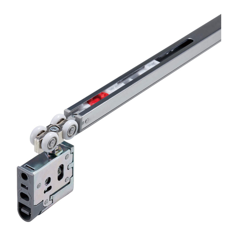
  9. SUGATSUNE Lamp FD30-F User manual

SUGATSUNE Lamp FD30-F User manual

①②③④⑤⑥⑦⑧ ⑨
Upper roller
(embed) Lower pivot Stopper block Striker Spanner Fixing metal Pivot bearing
(on floor)
Center hinge
(fascia) Rail (Fascia) Rail (Embed)
2 door, main door end fixed Select either type
2 1 1 1 1 1 1 3
4 door, main door end fixed Select either type
4 2 2 1 1 2 2
6
収納部
収納部
収納部
収納部
収納部
収納部
Trouble Check Point Remedy
Abnormal noise during
operation
Check if door touches other parts. Provide necessary space between door and adjacent objects.
Check inside of upper rail for foreign matter or
aluminum dust.
Remove dust or foreign matter.
Check rail rollers for aluminum dust. Remove the rail and pull out the roller. Then, clean the roller.
Check for loose screws retaining the upper rail. Tighten the screw.
Heavy door operation Door bottom touches the floor. Confirm that screws are not loosened. And, adjust door height. Adjust the
clearance between door bottom and floor to 16mm.
Check if door touches adjacent parts. Correct door position to avoid contact to other objects.
Adjust position of lower guide or stopper.
Check if door is warped. Use the door without warp.
Door does not move. Check rail retaining screws for looseness. Roller touches the screw.
Retighten screws to free the roller.
Door starts to move. Check the upper rail if it is set horizontally. Using a level gauge, reset upper rail horizontally.
■TROUBLESHOOTING
OPTIONAL PARTS (SOLD SEPARATELY)
No. Part Name
Dimensional Drawing
Specifications
1
Door end holder
pin
Order code:250-017-173
Part No.:FD30-FTF
●Material Polyamide/Steel
●Finish Natural
     /Colored chromating
●Accessory screw
 
Countersunk tapping screw 3×16
 
Countersunk tapping screw 3.5×16
No. Part Name
Dimensional Drawing
Specifications
2
Door end holder
(magnetic)
Order code:250-017-171
Part No.:FD30-FMF
●Material Polycarbonate
/ Neodymium
●Finish Dark brown
●Accessory screw
 
Flanged round head wood screw 3.1×16
 
Countersunk tapping screw 3.5×16
Thank you very much for selecting FD30-F CEILING MOUNT, FOLDING
DOOR SYSTEM.Before starting installation, please read this installation
manual thoroughly to install the door correctly. Improper installation
may result in injury. To prevent such accident, please follow instructions
described in this manual. After installing the door, leave this manual
to the owner so that the owner is able to use this manual to check the
door any time. The door system will be upgraded/improved without
announcement, for change in dimensions or specifications, please
confirm with delivered door system parts.
symbol denotes “warning” and ”caution” during work or operation. symbol
denotes the item which should be avoided to keep safety. symbol denotes
item which should be followed to avoid injury. If this item is not followed, injury
may be resulted.
■FOR YOUR SAFETY WORK AND OPERATION
This sliding door system should be installed by experienced person who has
correct knowledge. If the system is not installed correctly, the door will not operate
smoothly, and or may cause injury.
Do not try to use this product for any other purposes other than originally intended
for. Do not disassemble the components for any modifications. Do not use the
system for applications that are out of specification. Any improper use might result
in accident or injury. We do not take any responsibility for any damage, accident or
injury occurring from an improper use, application or wrong installation.
Avoid opening/closing the door with excessive force. Such operation may cause
trouble.
It is necessary to manufacture the frame having sufficient strength to endure the
weight of door and impact shocks upon opening/closing the door. The frame with
poor strength might result in improper and slower movement of the door. In the
worst case, door might drop down causing injury.
Warning: If this warning is not followed, injury or
damage of household good may be resulted.
IMPORTANT:
・
This manual is prepared to describe the installation methods
considered most safe and effective to set up and install the sliding
door system. The installation procedures or methods can be changed
to meet your working conditions or environments.
・
In this manual, the dimensions are not considering margin of error
or deformation of material. Therefore, please carry out each process
such as cutting, taking care of deformation or other changes.
・
In this installation manual, the dimension is used without consideration
of error by processing or assembly work or deformation of material
itself. In actual work such as cutting, therefore, should be carried out
considering actual work environment.
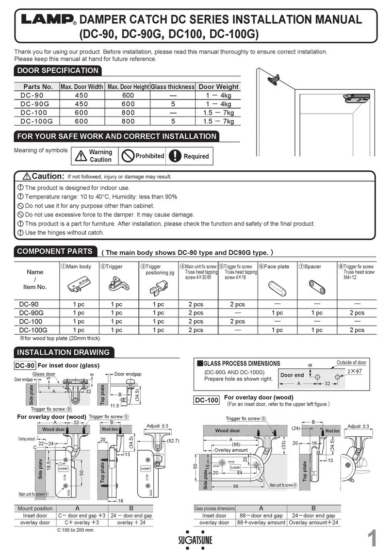
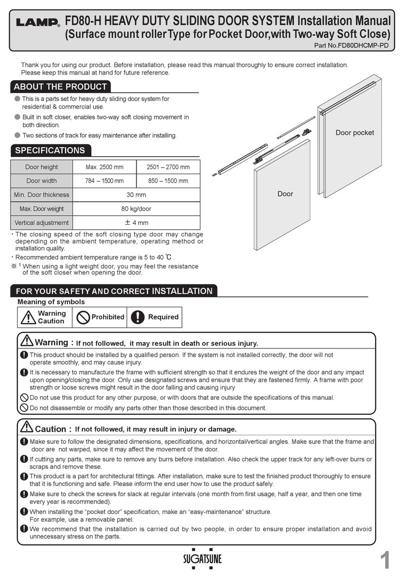
■SPECIFICATIONS
Max.Door width Min. Door thickness Max. Door height Max. Door weight Vertical adjustment
FD30-F 450mm 30mm 2400mm 15kg/door 3mm upward
As optional parts, upper roller cap, door end rolling stopper, etc. are offered. Please refer Page 4 for detail.
■ COMPONENT PARTS
1
3
1 6
8
2
7
Handle
(Optional)
9
右
上
下
左
4. Adjustment of door angle
With Philips screwdriver, adjust the
screw on center hinge.
Adjustment screw
※
※Adjust by hinge mount position.
Turn the screw clockwise (max: 2˚)
Turn the screw counterclockwise (max. 1˚)
178˚
179˚
Final confirmation…Confirm that all screws are securely tightened. And, confirm that all screws are used
without mistake.
右
上
下
左
FD30-F CEILING MOUNT, FOLDING DOOR SYSTEM
Installation Manual
(Main Door End Fixed Type)
Part No.
FD30UKP
ISO9001(Japan Offices and Sugatsune America) and ISO14001(Chiba Production division and Logistci center), certified.
2013.12 PRINTEDINJAPAN 0763-1 
PERIDICAL INSPECTION
・Clean inside of rail.
・Check upper space and lower space of the door. If necessary, correct the space.
np20d53.eps
np20d54.eps
13.8
3
5
15.5
27.6
Rest guide
np20d19.eps
np20d20.eps
8.5
3.5
4.5 4.5
714
15
φ13
23
33
3019
φ
3.5
19〜27
72
57.9
30
13
3
0.5
30 13
2266
4
8
28
φ4 φ8 CSK
右
上
下
左
右
上
下
左
According to “Shop Drawing” ,
temporary fix stopper block.
After adjusting the stopper block to
the position where both doors keep
“V” shape during folding them slowly,
and adjust such that doors move
smoothly when closing them, fix the
adjustor block firmly.
Stopper block
PROCEDURE
3
Continued. PROCEDURE
4
Adjusting stopper block position
3.
Left-to-right adjustment (+-2mm)
With Philips screwdriver, adjust
the position of upper roller.
右
上
下
左
nahrd04.eps
±2
Left-to-right
adjustment
screw
Do not rotate the adjustment screw
exceeding adjustment limit.
Damage may be resulted.
No.
Name Dimensional drawing Specification
①
Upper Roller
(recessed)
Single Part order code
:
250-017-135
Part No.
:
FD30-WRH
●
Material Zinc alloy/Polyacetal
●
Finish Colored Chromating
/Light brown
●
Attached screw
Tapping screw
3.5
×
30
②
Lower pivot
Single Part order code
:
250-017-163
Part No.
:
FD30-FBP
●
Material Polyamide/Steel
●
Finish
Natural/ Colored Chromating
③
Stopper block
Single Part order code
:
250-017-139
Part No.
:
FD30-HSB
●
Material Polyacetal
●
Finish
Dark brown
④
Pivot insert Jig
ー
Single Part order code
:
250-017-169
Part No.
:
FD30-FUK
⑤
Spanner for
folding door ー
Single Part order code:
250-017-168
Part No.
:
FD30-FSP
⑥
Fixing Metal
Single Part order code:
250-017-144
Part No.
:
FD30-FKK
●
Material Steel
●
Finish
Colored Chromating
No.
Name Dimensional drawing Specification
⑦
Pivot bracket
(Floor)
Single Part order code
:
250-017-170
Part No.
:
FD30-FPU
●
Material Steel
●
Finish Colored Chromating
(trivalent)
●
Attached screw
Truss head tapping screw
4
×
16
⑧
Center hinge
(surface mount)
Angle adjustable
Single Part order code
:
250-017-146
Part No.
:
FD30-CHM
●
Material Steel
●
Finish
electrode position in black
●
Attached screw
Tapping screw
3.5
×
16
⑨
Cover cap for
upper roller
Order code:250-017-138
Part No.:FD30-WRH-CP
●Material Polypropylene
●Finish Brown
⑩
Rail
(surface mount)
●
Material Aluminum alloy
●
Finish
Anodized aluminum
(Silver or amber)
●
Length
910mm,1820mm,
     2730mm,3640mm
●
Set screw is not attached.
(recommended screw is
tapping screw of 3.5
x
20)
Hole pitch:
300mm
Pitch end:30mm
Rail
(recessed mount)
■INSTALLATION DRAWING(EXAMPLE) ■Minimum Dimension between Frame and Door
3
Rail
(
Surface mount
)
Rail
(Recessed)
Door A Door B
(Pivot side)
11
6
8
2
7
10
±2
7
0
−3
About middle point
between upper and
lower hinges.
EC
D=32
Approx.132
Approx.
150
Approx.
150
When operating door:
Approx.179
+0
18.5
−0.5
21
右
上
下
左右
上
下
左
20
19.5
32
32
13
16
11
15 14
(Vertical adjustment amount)
7
0
−3
(Vertical adjustment amount)
1.2
32
19
40
14 Door A Dimension Door B Dimension
47
47.5
32
47
47.5
16
R8
φ12
38
16
R8
5
φ22
Back doorBack door
3
If any foreign matter such as cutting chips are remained in the rail, roller and guide may have such foreign
matter causing abnormal sounds during door operation. Please carefully remove cutting chips or the like.
1. Cutting the rail
Cut the rail applying a reinforcer to prevent
deformation of cut section.
2. Preparation before mounting parts
Pull up the lever of upper roller to separate main body
from casing. (When removing the door for adjustment
after finishing door installation, the door can be
removed by raising the lever.)
Loosen fixing screw on fixing metal.
4. Assembly of parts
aking care for parts directions, install upper
roller (main unit), stopper block. Then, install
the upper roller with fixing metal groove aligned
to upper roller groove. Install assembled rail.
5. Inserting lower pivot
Into the hole prepared at bottom of
the fixing side, insert the lower pivot
with the Jig. Work must be done
carefully not to damage resin of the
pivot.
1. Temporary setting fixing part
Temporary mount fixing part built-in the rail,
referring “Shop Drawing”
右
上
下
左
2. Fixing door (Door bottom)
Position end of lower pivot, installed door
bottom, into hole on pivot bracket.  
右
上
下
左
3. Hanging door
Insert upper roller main unit into the casing
installed on door until click sound is heard.
7. Installing pivot bracket
Mount pivot bearing to specified position at
door fixing side using attached screws. Take
care for mounting direction.
Fixing metal
Pivot bracket
Lower pivot Upper roller
(casing)
6. Installing center hinge
Aligning two doors, fix center hinge
with attached screws. Center of
the hinge should be positioned at
approximately 150mm from top of door
as well as bottom of door. Please note
that both hinges face same direction.
Remained hinge should be installed at
middle of upper and lower hinges.
Rail
Screws may be
replaced so that the
hole for placing the
pivot is positioned to be
outside.
Fixe pivot bearing with attached screws.
Door fixing
side
Confirm that upper roller main unit is not
dislocated.
Upper roller
(casing)
3. Installing casing
Firmly insert upper rollerr casing into the
place as shown, fix it with attached screws.
右
上
下
左
np20d34.eps
38
54
34
15
12
12
15
70
2
7
13.9
8×φ4 φ
7 CSK
nh03d04.eps
19.5
20
9.2
φ
4.8
φ
7.8 CSK
nh03d31.eps
18.2
1.2
20
9.2
23
φ4.8 φ7.8 CSK
2
np20d03.eps
np20d17.eps
nh03d03.eps
nh03d32.eps
np20d33.eps
np20d41.eps
22
φ16
39
30
45
16.6
16
47.5
右
上
下
左
nh03d02.eps
np20d04.eps
38
55
φ12
φ6
φ20
6.5〜17
179
18
2
8
6
58.1 9.5
28.6
20
3.2
np20d42.eps
np20d18.eps
13
9
11 7
6
16
50
30〜40
80
2×5×11 Ellipse hole
40
Confirmation
before assembly
・
Check that dimensions of frame, floor, door and rail are correct.
・
Check that frame and floor are not inclined.
・
Check that door is processed correctly.
・
Check that door is not warped.
・
Check that all parts are prepared.
■DOOR PROCESS DIMENSION
Pivot insert Jig
Bottom of door
(Fix side)
Lower pivot
■ASSEMBLY
17.2
16.69
Philips retaining
screw
M5×16
nh03d23.eps
2
12
46.8
15.8
nh03d24.eps
Door
thickness
C = Gap
E = Gap
Door width
300
Door width
350
Door width
400
Door width
450
30 4.0 3.5 3.0 2.7 2.4
35 5.2 4.3 3.7 3.3 3.0
40 6.5 5.2 4.5 4.0 3.6
Move the door slowly.
When door is not moved smoothly,
adjustment may be needed to correct door
position.
Adjustable part positions are; upper roller,
lower pivot center hinge and stopper block.
Make necessary adjustment so that the door
will move smoothly.
Range of adjustment are set by each part.
However, adjustment range may be differed
depending upon parts combination or
installation methods.
1.
Adjusting inclination of door
Set the door to vertical
position by removing
fixing screws on fixing
metal and pivot bearing.
Then replace fixing
screws to vertical door
position.
2.
Adjusting vertical position
(+- 4mm)
Adjust Hex. nut on lower
pivot with folding door
spanner. Adjust vertical
position adjustment screw
on upper roller with Phillips
screwdriver.
右
上
下
左
Fixing screw for
fixing metal
Fixing screw for
pivot bracket
74
右
上
下
左
Lower pivot
Pivot bracket Folding door spanner
Vertical position
adjust screw
Clockwise =Raise
Counterclockwise=Lower
右
上
下
左
nahrd04.eps
右回し=上がる
左回し=下がる
7±4
±4
PROCEDURE
1
PREPARATION AND INSTALLATION
PROCEDURE
2
HANGING DOOR
PROCEDURE
3
CONFIRMATION OF DOOR MOVEMENT AND ADJUSTMENT
右
上
下
左
Upper roller
(main unit)
Fixing metal
Groove
Fixed main door
Door top side
Upper roller
(casing)
Upper roller
(main unit)
右
上
下
左
右
上
下
左
Lever
Fixing metal
右
上
下
左
右
上
下
左
Stopper block

Other SUGATSUNE Door Opening System manuals

SUGATSUNE Aileron Lift-Assist User manual

SUGATSUNE

SUGATSUNE Aileron Lift-Assist User manual

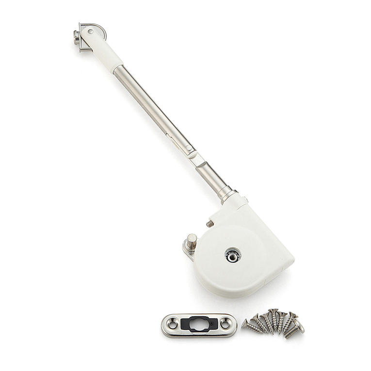
SUGATSUNE Lapcon SDS-C301N-BLK User manual

SUGATSUNE

SUGATSUNE Lapcon SDS-C301N-BLK User manual

SUGATSUNE LAMP LL-66S User manual

SUGATSUNE

SUGATSUNE LAMP LL-66S User manual

SUGATSUNE LAMP LM-80 User manual

SUGATSUNE

SUGATSUNE LAMP LM-80 User manual

SUGATSUNE LAMP FD80-H User manual

SUGATSUNE

SUGATSUNE LAMP FD80-H User manual

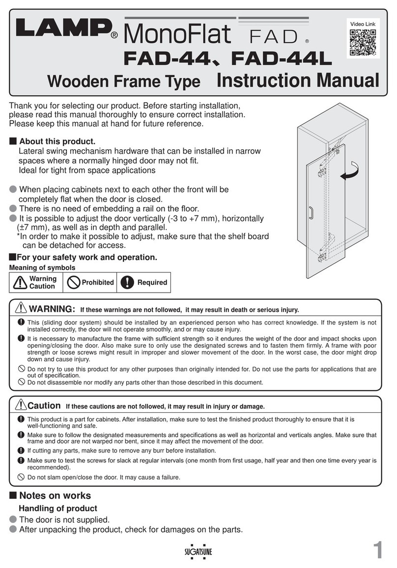
SUGATSUNE LAMP MonoFlat FAD Series User manual

SUGATSUNE

SUGATSUNE LAMP MonoFlat FAD Series User manual

SUGATSUNE LAMP DC Series User manual

SUGATSUNE

SUGATSUNE LAMP DC Series User manual

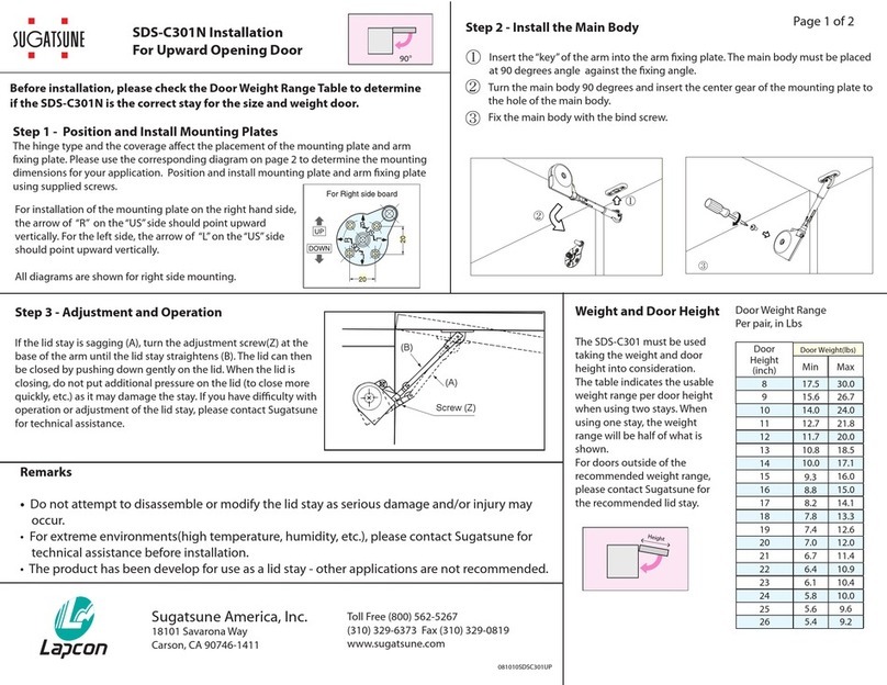
SUGATSUNE SDS-C301N User manual

SUGATSUNE

SUGATSUNE SDS-C301N User manual

SUGATSUNE LAMP FD35EV User manual

SUGATSUNE

SUGATSUNE LAMP FD35EV User manual

SUGATSUNE Zwei L ZL-2402 User manual

SUGATSUNE

SUGATSUNE Zwei L ZL-2402 User manual

SUGATSUNE LAMP ALT-F User manual

SUGATSUNE

SUGATSUNE LAMP ALT-F User manual

SUGATSUNE HES2S-140-A125 User manual

SUGATSUNE

SUGATSUNE HES2S-140-A125 User manual

SUGATSUNE LAMP FD50-H User manual

SUGATSUNE

SUGATSUNE LAMP FD50-H User manual

SUGATSUNE LAMP FD50-H User manual

SUGATSUNE

SUGATSUNE LAMP FD50-H User manual

SUGATSUNE EB-90 User manual

SUGATSUNE

SUGATSUNE EB-90 User manual

SUGATSUNE LAMP Lapcon SDS-210 User manual

SUGATSUNE

SUGATSUNE LAMP Lapcon SDS-210 User manual

Popular Door Opening System manuals by other brands

GEZE MSW manual

GEZE

GEZE MSW manual

hager 8300 Series Installation and service manual

hager

hager 8300 Series Installation and service manual

Salto XS4 KPB14 Series manual

Salto

Salto XS4 KPB14 Series manual

Dorex DX2 PC installation instructions

Dorex

Dorex DX2 PC installation instructions

CAME 803XA-0320 instructions

CAME

CAME 803XA-0320 instructions

SIMONSWERK Anselmi AN 150 3D 28 manual

SIMONSWERK

SIMONSWERK Anselmi AN 150 3D 28 manual

Assa Abloy Norton LEO 5700 Series instructions

Assa Abloy

Assa Abloy Norton LEO 5700 Series instructions

Assa Abloy Norton 5630 Series Installation and instruction manual

Assa Abloy

Assa Abloy Norton 5630 Series Installation and instruction manual

RUSTICA STAG HANGER installation instructions

RUSTICA

RUSTICA STAG HANGER installation instructions

Falcon SC71 installation instructions

Falcon

Falcon SC71 installation instructions

Metaflex MF7 manual

Metaflex

Metaflex MF7 manual

GEZE GC 308 R installation instructions

GEZE

GEZE GC 308 R installation instructions

Lock Control DH-66 Series Installation and operation manual

Lock Control

Lock Control DH-66 Series Installation and operation manual

Cal-Royal 8600 Operation & installation manual

Cal-Royal

Cal-Royal 8600 Operation & installation manual

Helm GT-L 80 G 412 manual

Helm

Helm GT-L 80 G 412 manual

Dorma Manet Mounting instruction

Dorma

Dorma Manet Mounting instruction

Dormakaba RTS88 installation instructions

Dormakaba

Dormakaba RTS88 installation instructions

Mowin R60 instruction manual

Mowin

Mowin R60 instruction manual

manuals.online logo
manuals.online logoBrands
  • About & Mission
  • Contact us
  • Privacy Policy
  • Terms and Conditions

Copyright 2025 Manuals.Online. All Rights Reserved.