Ronan X54-201L Parts list manual

Instructions
and
Operating Manual
SERIES X54-201L/SR
LOOP-POWERED
INDICATOR

Table of Contents
1.0 General Description . . . . . . . . . . . . . . . . . . . . . . . . . . . . . . . . . . . . . . . . . . . . . . . . . . . . . . . . . . . . . . . . . . . . .2
2.0 Specifications . . . . . . . . . . . . . . . . . . . . . . . . . . . . . . . . . . . . . . . . . . . . . . . . . . . . . . . . . . . . . . . . . . . . . . . . .2
3.0 Operation . . . . . . . . . . . . . . . . . . . . . . . . . . . . . . . . . . . . . . . . . . . . . . . . . . . . . . . . . . . . . . . . . . . . . . . . . . . .2
3.1 General . . . . . . . . . . . . . . . . . . . . . . . . . . . . . . . . . . . . . . . . . . . . . . . . . . . . . . . . . . . . . . . . . . . . . . . . . . . . . .2
3.2 Span Selection . . . . . . . . . . . . . . . . . . . . . . . . . . . . . . . . . . . . . . . . . . . . . . . . . . . . . . . . . . . . . . . . . . . . . . . .3
3.3 Zero Selection . . . . . . . . . . . . . . . . . . . . . . . . . . . . . . . . . . . . . . . . . . . . . . . . . . . . . . . . . . . . . . . . . . . . . . . . .3
3.4 Decimal Point Selection . . . . . . . . . . . . . . . . . . . . . . . . . . . . . . . . . . . . . . . . . . . . . . . . . . . . . . . . . . . . . . . . . .3
3.5 Linear or Square Root Function Selection . . . . . . . . . . . . . . . . . . . . . . . . . . . . . . . . . . . . . . . . . . . . . . . . . . . .3
4.0 Calibration . . . . . . . . . . . . . . . . . . . . . . . . . . . . . . . . . . . . . . . . . . . . . . . . . . . . . . . . . . . . . . . . . . . . . . . . . . . .4
4.1 Linear Display, Model X54-201L . . . . . . . . . . . . . . . . . . . . . . . . . . . . . . . . . . . . . . . . . . . . . . . . . . . . . . . . . . .4
4.2 Square Root Display, Model X54-201SR . . . . . . . . . . . . . . . . . . . . . . . . . . . . . . . . . . . . . . . . . . . . . . . . . . . . .4
5.0 Drawings
X54-201 Explosion Proof Assembly, X54C92 . . . . . . . . . . . . . . . . . . . . . . . . . . . . . . . . . . . . . . . . . . . . . . . . . .5
X54-201 Panel Mount Assembly . . . . . . . . . . . . . . . . . . . . . . . . . . . . . . . . . . . . . . . . . . . . . . . . . . . . . . . . . . .6
X54-201L/SR Installation Drawing Using I.S. Barriers or Explosion Proof Conduit . . . . . . . . . . . . . . . . . . . . . .7
Warranty
Ronan warrants equipment of its own manufacture to be free from defects in material and workmanship under normal
conditions of use and service, and will repair or replace any component found to be defective, on its return,
transportation charges prepaid, within one year of its original purchase. This warranty carries no liability, either
expressed or implied, beyond our obligation to replace the unit which carries the warranty.
1

1.0 GENERAL DESCRIPTION
Ronan’s Models X54-201L and -201SR are 3½-digit loop
powered indicators which display linear (-201L) and
square root (-201SR) values of the associated loop
current. The loop containing one of these indicators is
barely effected as the indicators require less than 1 V to
operate. These versatile modules allow the selection of
a linear or square root display, zero value, span and
decimal point through the placement of plug-in jumpers.
Spans from 0.100 to 1999 and span zeros from –360 to
+1300 are selected by the plug-in jumpers. The decimal
point selector plug may be placed in any one of four
positions which selects one, two or three digits to the
right of the decimal point or in position 0 for no decimal
point.
2.0 SPECIFICATIONS
Note: Specifications apply at 25ºC ± 2ºC unless
otherwise stated. Specifications subject to change
without notice.
Input: 4-20 mA.
Input Protection: Diode protected against
reverse polarity.
Voltage Drop: Less than 1 V.
Span Selection: Spans from 0.100 to 1999 digits are
selected by DIP-switch settings accessible at the top
board of the module. Refer to Table 3-1 on page 3.
Span Adjustment: Front-accessible, multi-turn
potentiometer allows ± 20% adjustment of all ranges.
Zero-offset Selection: Offsets from –360 to +1300
digits are selected by DIP-switch settings accessible at
the top board of the module. Refer to Table 3-2 on
page 3.
Zero Adjust: Front accessible, multi-turn potentiometer
allows ± 10% adjustment of selected span range.
Decimal Point Selection: Plug-in jumpers, accessible
at the top board of the module, allow selection of the
decimal point position. See section 3.5.
Accuracy:
Linear Display: ± 0.1% of span or ±1 digit.
Square Root Display: ± 0.3% of span or ± 1 digit
(applies from 4.3 to 20 mA input).
Operating Ambient Temperature Range: –10º to
+55ºC.
Temperature Coefficient:
Zero: ± 0.01% of Span/ºC, ± 0.01% of elevated zero
value/ºC.
Span: ± 0.015% of Span/ºC.
Display: 3½-digit LCD, black digits on a reflective
background.
Terminals: Compression type for wire size up to #14
AWG.
3.0 OPERATION
3.1 General
Model X54-201 is put into service by connecting it
in series with 4-20 mA current loop. The
connections are made to the two-position
compression-type screw terminal mounted on the
lower board and accessible from the top of the
module. The loop indicator module needs to be
removed from the enclosure in order to feed the
wires past the bottom board and into the screw
terminals. To remove the module from the
explosion-proof enclosure:
A. Unscrew and remove the enclosure cap.
B. Snap off the top plate of the module and insert
your index finger into cutout and remove the
plate.
C. Loosen the two module captive mounting
screws until the module is free.
D. Remove the module from the enclosure and
fasten the input wiring to the screw terminals.
E. Connect the lead that returns back to the –
output of the power supply, either directly or
through a two wire transmitter, to the – terminal
of the X54-201. Connect the other wire to the +
terminal. See Figure 3-1.
F. Re-install the module and enclosure cap.
The Model X54-201 Loop Powered Indicator is
normally shipped calibrated to ranges as specified
by the purchaser. However, it is designed to allow
easy reconfiguration in the field. The span is
changed by changing the position of one or two of
the SW1 switches -1 through -5. The span zero
value is changed by changing the settings of SW2
switches -1 through -6 and SW1-6.
Figure 3-1: Wiring Diagram
2
X54-201 Approvals (_PM2 and _EXP2)
Factory Mutual Approvals
-EXP2 Housing = Explosion Proof -Class I-III, Div. 1, Grps B-G and NEMA 4
= Intrinsic Safe -Class I-III, Div, Div. 1, Grps A-G and NEMA 4
-PM2 Housing = Div. 2 Applications -Class I, Div. 2, Grps A-D
= Intrinsic Safe -Class I, Div.1, Grps A-D
CSAApprovals
-EXP2 Housing = Explosion Proof -Class I-II, Div. 1, Grps B-G
= Intrinsic Safe -Class I-II, Div. 1, Grps A-G
= Div. 2 Applications -Class I-II, Div. 2, Grps A-G
-PM2 Housing = Div. 2 Applications -Class I, Div. 2, Grps A-D
= Intrinsic Safe -Class I-II, Div. 1, Grps A-G
CENELEC Approvals
X54-201-MI (EXP housing)
Intrinsic Safe -EEx ia IIC T4 (Tamb = 85°C)
-EEx ia IIC T5
X54-201-MX (EXP Housing)
Flame Proof -EEx d IIC T6
-
+

3.5 Linear or Square Root Function
Selection
Model X54-201L provides a display which is a
linear representation of the input, and Model X54-
201SR provides a display which is the square root
function of the input. The square root display
versus the input current can be found as follows:
DISPLAY = (mA –4 mA) ÷ 16 mA × Display
Range + Display Zero;
Or,
DISPLAY = 0.25 mA Input – 4 × Display Range
+ Display Zero.
In order to change the X54-201’s function from
linear to square root, or vice versa, the module
must be removed from its enclosure as the
function jumper plugs are located on the bottom
board. The jumpers are located at JP1 and JP2
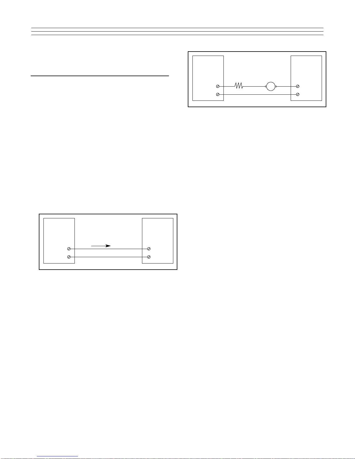
3.2 Span Selection
Refer to Table 3-1 to obtain the spans shown in
the left column which indicates the positions of
SW1-1 through SW1-5. For example, a span of
2.00, 20.0 or 200, SW1-2 and -5 are set to the ON
position and SW1-1, -3 and -4 are OFF.
3.3 Zero Selection
Table 3-2 indicates which positions of SW2-1
through SW2-6 and S1-6 are set to ON to obtain
the zero offset, in digits, indicated in the columns
directly below the switch. The indicated offsets are
additive, i.e., two or more of the switches may be
set to their ON position to obtain the sum of their
indicated offsets. The display span is located in
the left column, then the offset digits are found in
the same row as the display range. When the
desired offset digits are found, the switch or
switches, at the head of the column(s) should be
set to the ON position.
When changing spans or offsets, the zero and
span controls will need to be fine tuned to obtain
the specified accuracy. See Section 4.0
Calibration, for a procedure to adjust the zero and
span controls.
3.4 Decimal Point Selection
The decimal point position is selected by the
position of the DP-jumper plug located at the
lower left edge of the display board. The jumper
plug can be placed in any one of the following four
positions: 0, 1, 2 or 3, and corresponds to (0) no
decimal point, (1) one digit to the right of the
decimal point, (2) two digits to the right of the
decimal point, or (3) three digits to the right of the
decimal point.
√
√
SW1-1 SW1-2 SW1-3 SW1-4 SW1-5
1.00, 10.0, 100 Off Off Off On On
1.40, 14.0, 140 Off Off On Off On
2.00, 20.0, 200 Off On Off Off On
3.00, 30.0, 300 On Off Off Off On
4.00, 40.0, 400 Off Off Off Off On
5.00, 50.0, 500 Off Off Off On Off
7.00, 70.0, 700 Off Off On Off Off
10.00, 100.0, Off On Off Off Off
1000
15.00, 150.0, On Off Off Off Off
1500
19.99, 199.9, Off Off Off Off Off
1999
Display Spans
Digits ± 20% Selection of Span Switches, SW 1
SW2- SW2- SW2- SW2- SW2- SW2- SW1-
1234566
1.00, 10.0, 5 10 20 40 80 160 –60 200
100 *120
1.40, 14.0, 7 14 28 56 110 220 –90 275
140 *160
2.00, 20.0, 10 20 40 80 160 320 –125 400
200 *240
3.00, 30.0, 15 30 60 120 240 480 –190 600
300 *360
4.00, 40.0, 20 40 80 160 300 600 –230 760
400 *460
5.00, 50.0, 25 50 100 200 400 800 –100 1000
500 *600
7.00, 70.0, 35 70 140 280 560 1120 –140 1300
700 *1300
10.00, 100.0, 50 100 200 400 800 N/A –200 1000
1000 *1000
15.00, 150.0, 75 150 300 600 N/A N/A –300 500
1500 *500
19.99, 199.9, N/A N/A N/A N/A N/A N/A –360 N/A
1999
Display
Spans
Digits
± 20%
Max.
Offset
Digits Offset Vs Offset Switches, SW2 and SW1-6
* Equals Square Root Mode.
Note: Offset of 2 or more switches may be combined.
Table 3-2: Digits Offset.
JP1 Position JP2 Position
Jumpered Jumpered
Linear 1,2 1,3
Square Root Not used 1,2,3,4
Table 3-3: JP1 and JP2 plug positions for selection of linear or square root
function.
3
Table 3-1: Selection of Span Switches, SW1

ADJUSTABLE MILLIAMMETER
RESISTOR
4-20 mA
near the right center section of the bottom P.C.
Board. Table 3-3 shows the location of the jumper
plugs for linear or square root operation.
4.0 CALIBRATION
The Models X54-201L and -201SR can be readily
calibrated with the use of an accurate calibrator like
Ronan’s Models X85 or X86 (Figure 4-1). Alternately, a
stable power supply in series with an accurate
milliammeter and current setting resistor may be utilized
(Figure 4-2). When using the circuit of Figure 4-2,
ensure that the current limiting resistor is large enough
to limit the loop current to less than 50 mA to avoid
blowing the protective fuse before turning on the power
supply.
4.1 Linear Display, Model X54–201L
A. Set the calibrator to its mA output range and
4.00 mA, or set the current using the circuit
of Figure 2 to 4.00 mA.
B. Adjust the zero control for the correct span
zero display.
C. Repeat Step A using 20.00 mA.
D. Adjust the span control for the correct span
full scale display.
E. Repeat Steps A through D until the controls
no longer need adjustment.
4.2 Square Root Display, Model
X54–201SR
A. Set the calibrator to its mA output range and
4.3 mA, or set the current using the circuit of
Figure 4-2 to 4.3 mA.
B. Adjust the zero control for the correct display:
DISPLAY = .137 x Display Span + Span Zero
C. Repeat Step A using 20.00 mA
D. Adjust the span control for the correct span
full scale display.
E. Repeat Steps A through D until the controls
no longer need adjustment.
Figure: 4-1: Calibrator used to provide 4-20 mA.
RONAN
MODEL X85
OR X86
CALIBRATOR
mA
OUTPUT
X54-201
LOOP
INDICATOR
4-20 mA
+
-
+
-
DC
POWER
SUPPLY
X54-201
LOOP
INDICATOR
+
-+
-
Figure: 4-2: Calibrator circuit using dc power supply.
➔
4

Item No. Qty. Code/Part No. Description Spec.
1 1 X54-201L, -201SR PCB X54-1026 & X54-1027 Assy. RONAN
2 1 X54B156 MTG. RING, TOP RONAN
3 1 X54B157 MTG. RING, MIDDLE RONAN
4 1 X54B158 MTG. RING, BOTTOM RONAN
5 2 X54B159 CAPTIVE SCREW RONAN
6 1 X54B165-1 WIRE ASSY. RONAN
7 1 X54B165-2 WIRE ASSY. RONAN
8 1 X54B86-1 FRONT PLATE RONAN
9 1 X54B88 BASE PLATE RONAN
10 1 XIHFGCX2LS42311 E.P. HOUSING ADALET
11 1 600-4 TERMINAL BLOCK KULKA
12 2 6-32 X 0.375 PH PAN HD MS
13 4 8-32 X 0.250 PH PAN HD MS
14 2 4-40 X 1.250 PH FLAT HD MS
15 4 #8 INTER TOOTH LKWR
16 1 X54B229 DECAL SET
X54-201
Exp. Proof Assy. DRAWING NUMBER
X54C92 REV
8
5

X54-201
PANEL MOUNT ASSY. DRAWING NUMBER
X54C112 REV
5
Item No. Qty. Code/Part No. Description Spec.
1 1 X54-201L, -201SR PCB X54-1026 & X54-1027 Assy. RONAN
2 1 X54B156 MTG. RING, TOP RONAN
3 1 X54B157 MTG. RING, MIDDLE RONAN
4 1 X54B158 MTG. RING, BOTTOM RONAN
5 2 X54B159 CAPTIVE SCREW RONAN
6 1 X54C119 TERMINAL PLATE RONAN
7 1 X54B86 FRONT PLATE RONAN
8 1 X54B165-3 WIRE ASSY. RONAN
9 1 GFTCX-5 TERMINAL BLOCK CURTIS
10 2 TINNERMAN NUT CURTIS
11 1 20 AWG 6.00 IN. LG. RED UL1429 WIRE
12 1 22 AWG 6.00 IN. LG. BLK UL1429 WIRE
13 1 6-32 X 0.250 PH PAN HD MS
14 2 4-40 X 1.250 PH FLAT HD MS
15 1 #6 INTER TOOTH LKWR
6

7
X54-201L/SR
INSTALLATION DRAWING
USING I.S. BARRIERS OR
EXPL. PROOF CONDUIT DRAWING NUMBER
X54D105 REV
6
NOTES:
1. Subject loops must be connected in accordance with
ANSI/ISA RP12.6
2. Barrier parameters must meet the following requirements:
CAUTION: THESE REQUIREMENTS MUST BE
FOLLOWED FOR NEW INSTALLATIONS
OR MODIFICATIONS TO EXISTING
INSTALLATIONS.
Vt or Voc ≤The lowest Vmax of the three FMRC
Approved apparatus installed in the loop,
and greater than 4.5 VDC
It OR Ioc ≤The lowest Imax of the three FMRC
Approved apparatus installed in the loop.
La > The sum of the cable inductance and the
internal inductance Li of each FMRC
Approved apparatus installed in the loop.
Ca > The sum of the cable capacitance and the
internal capacitance Ci of each FMRC
Approved apparatus installed in the loop.
3. Maximum safe area voltage should not exceed 250 Vrms.
4. De-energize supply power before disconnecting loop
apparatus.
5. Vmax and Imax values do not apply in explosion proof
installation.
6. For Class II and III applications, model X54-201L/SR-EXP2
housing must be installed with Approved seal.
7. For Division 2 installations, connection of the X54-201 l/SR
in the panel mount or EXP. PROOF ENCLOSURES does not
require a safety barrier when installed per the national
electrical code and when connected in a loop whose voltage
source cannot exceed 35 Vdc.

RONAN ENGINEERING
COMPANY
P.O. Box 1275
21200 Oxnard Street
Woodland Hills
California 91367 U.S.A.
(818) 883-5211
FAX (818) 992-6435
E-Mail: [email protected]
RONAN ENGINEERING
LIMITED U.K.
1 Tilley Road
Crowther Industrial Estate
Washington, Tyne and Wear
United Kingdom, NE38 OEA
E-Mail: [email protected]
Ph: (191) 416-1689
Fx: (191) 416-5856
RONAN ENGINEERING
LIMITED
32 Bermondsey Road
Toronto, Ontario
Canada M4B 1Z5
(416) 752-0310
FAX (416) 752-8072
E-Mail: [email protected]
Printed in U.S.A.X54-201L-SR/600
This manual suits for next models
1
Table of contents