Ronda xtratech 4220.B User manual

Quartz Movements
Multifunctions
RONDA xtratech
Caliber 4220.B – 12½'''
Product Specifications
Analog quartz movement
Line xtratech
Caliber 4220.B
Size 12½'''
Version Swiss Made 7 Jewels / gold plated
Standard battery life 54 months
Standard hand fitting height 2
Functions
• Multifunction
• Second time zone
• Big date
• Small second
• 2 hands
Features
• Repairable metal watch movement
• Power saving mechanism with pulled out stem:
Reduction of consumption approximately 70%
• Very easy handling by one pusher
• Big date with quick change
ronda.ch
1/2

Quartz Movements
Multifunctions
RONDA xtratech
Caliber 4220.B – 12½'''
Technical Specifications
Diameter Total 28.60 mm
Case fitting 28.00 mm
Movement height 4.40 mm
Height over standard battery 4.40 mm
Movement rest 0.60 mm
Height over stem 1.90 mm
Length of stem travel 0.90 mm
Stem thread 0.90 mm
Useful torque second – typical 6 μNm
Useful torque minute – typical 300 μNm
Operating temperature 0 - 50 °C
Instantaneous rate -10/ +20 sec/month
Resistance to magnetic fields 18.8 Oe
Resistance against shock NIHS 91-10
Battery Specifications
Standard battery No. 395
Standard battery life 54 months
Battery voltage 1.5 V
Current consumption – typical 1.32 μA (Date Mechanism
not in Gear)
Current consumption – maximum 1.65 μA (Date Mechanism
not in Gear)
ronda.ch
2/2
08/2023

02
No. 5000.348
4220.B
Sous réserve de modifications
Aenderungen vorbehalten
Modifications reserved
Frame
Cage
RONDA
Urwerkgestell 12½'''
02 Mär 2004
Modified
Scale 10 : 1 (5 : 1) (A3H)
+/- 20 µm
mkIssued
Tolerance
Released
dh
ÄA 34777
YES
05 Sep 2016
6.85
Centre<->compteur
Zentrum<->Zähler
Center<->counter
Sécurité
Sicherheit
Security
0.3 2.55
Aiguillage No.2
Zeigerwerkhöhe Nr.2
Hand height Nr.2
Important: l'aiguillage peut varier selon le modèle
Wichtig: die Zeigerwerkhöhe kann bei verschiedenen Modellen unterschiedlich sein
Important: the hand height can vary between different models
4.4 +150
-0
1.4
Ø 28.6 +0
-30
Ø 28 +0
-30
0.6 ±10
0.00-0.15
0.6
0.00-0.10
Sécurité entre l'aiguille des secondes et le verre:
Sicherheit zwischen Sekundenzeiger und Glas: 0.30mm
Security between second hand and glass:
Le cadran doit être tenu par la boîte
Das Zifferblatt muss durch die Schale gehalten werden
The dial must be hold by the case
La course du poussoir doit être limitée dans le
poussoir lui-même. Sa position poussée doit être
controlée.
Die Weglänge des Drückers ist im Drücker selbst zu
begrenzen. In der gedrückten Stellung ist seine
Position zu kontrollieren
The way of the pusher has to be limited in the
pusher itself. Its position must be checked while
pushed in.
Vis
Schraube Nr. 4000.310
Screw
2
(R 13.43)
0.25
Ø 2.2
0.8
0.75
0.3
Vis
Schraube Nr. 4000.195
Screw
Ø 1.8 Ø 2.2
2.45
0.25
Vis
Schraube Nr. 4000.194
Screw
1.8
Stellwelle
Tige
Stem
Filetage:
Gewinde: S 0.90
Thread:
Chemin:
Weg: 0.90
Way:
1.9
Ø 1.10
course
Weg 1.00
way
Position poussée
Gedrückte Stellung R 13.50 ±50
Pushed in
Poussoirs
Drücker
Pushers
2.7
Ø2.4
S0.8
9.75
5.98
6.32
5.35
12.3213.26
2.1
Côté fond de boîte
Seite Gehäuseboden
Case back side
B 30° ±1
A 30° ±1
2.5
1.25
2.5
1.25
Position pour extraire la tige
Position zum Entfernen der Stellwelle
Position to remove the stem
Pile
Batterie (395) Ø 9.50 x 2.60mm
Battery
Dégagement cercle d'entourage pour poussoir
Freistellung Gehäusering für Drücker
Opening movement holder for pusher
L'angle indiqué pour la direction du poussoir
et la position doivent être respectés.
Pour un angle de 0°des poussiors A et B,
voir plan 5000.345
Der angegebene Winkel für die Drückerrichtung und
die Position müssen eingehalten werden.
Für einen Drückerwinkel von 0°bei A und B, siehe
Zeichnung 5000.345
The indicated angle of the pusher direction and
the position must be fullfilled. For pusher angles
of 0°(pusher A and B), see drawing 5000.345.
min. ø 28.6
min. 3.9
cercle d'entourage
Gehäusering
movement holder
Seulement 1 poussoir
est nécessaire
Nur 1 Drücker
wird benötigt
Only 1 pusher
is required

b
30°
Ø Dp
30°
b
T
ØDe
ØDt
P
Ø1.2
±200
ØDp
Ø Dp
0°
a b
b
aT
ØDe
ØDt
P
30° ±2
Ø 0.4
Ø 1.4 +0
-100
Ø Dp
Ø Dp
20°
a b
b
20°
aT
ØDe
ØDt
P
Ø0.4
Ø1.4
+0
-100
ØDp
10° ±2
Ø Dp
15°
a b
b
15°
aT
ØDe
ØDt
P
Ø0.4
15° ±2
Ø1.4
+0
-100
ØDp
Ø Dp a b
10°
b
10°
aT
ØDe
ØDt
P
Ø0.4
Ø1.4
+0
-100
ØDp
20° ±2
01
No. 5000.345
4xxx.x, 5xxx.x
Sous réserve de modifications
Aenderungen vorbehalten
Modifications reserved
Angle of pusher A and B
Winkel der Drücker A und B
Angle des poussoirs A et B
RONDA
Modified
Scale 10 : 1 (5 : 1) (A3H)
+/- 20 µm
mkIssued
Tolerance
Released
30.März 2005 mk
ÄA 1784
YES
06 Sep 2004


EF
Ø 0.900 +6
-4
Ø 1.500 +4
-2
Cylindrique
Zylindrisch
Cylindrical
L
K
Ajustement aiguille des minutes
Minutenzeigerpassung
Minute hand fitting
Ajustement aiguille des heures
Stundenzeigerpassung
Hour hand fitting
Cylindrique
Zylindrisch
Cylindrical
Ajustement aiguille des heures
Stundenzeigerpassung
Hour hand fitting
Ajustement aiguille des minutes
Minutenzeigerpassung
Minute hand fitting
Appui cadran
Zifferblattauflage
Dial seat
Heures / minutes
Stunden / Minuten
Hours / minutes
04
No. 3316.083
4120.B, 4220.B
Sous réserve de modifications
Aenderungen vorbehalten
Modifications reserved
Hand fitting heights
Aiguillages
RONDA
14 Nov 2003
Modified
Scale 20 : 1 (A3H)
µm
mkIssued
Tolerance
YesReleased
15 Okt 2014 dh
ÄA 13275
Zeigerwerkhöhe 12½'''
Compteur 2 aiguille
2 Zeiger Zähler
2 Hand counter
Masse / Masse / Weight *
Balourd / Unwucht / Unbalance *
Aig. des minutes
Minutenzeiger
Minute hand
Aig. des heures
Stundenzeiger
Hour hand
Inertie / Massenträgheit / Inertia *
Force de chassage / Aufpresskraft / Force
gmm
2
µNm
mg
N
max.
max.
max.
max.
Lors de la pose d'aiguilles, le mouvement
doit être soutenu.
Beim Zeigersetzen muss das Werk
abgestützt werden.
The movement needs to be supported
for hand setting.
0.80
40 40
0.80
30 30
- -
10 10
30 30
1.0 -
0.03 0.03
10
30
0.4
0.07
Aig. des heures
Stundenzeiger
Hour hand
Aig. des minutes
Minutenzeiger
Minute hand
Ajustement aiguille
Zeigerpassung
Hand fitting
+6
-4
Ø 0.206
0.3
J
Aig. petite secondes
Kleine Sekundenzeiger
Small second hand
Petite seconde
Kleine Sekunde
Small second
0.25
Ø 0.400 +6
-4
Ø 0.800 +4
-2 Ø 0.5 max.
Ø 0.200
Chaussée
Minutenrohr
Cannon-pinion
Roue des heures
Stundenrad
Hour wheel
Dépassement
Höhe über Zifferblattauflage
Height over dial seat
1.95 1.522
Aiguillages
Zeigerwerkhöhe
Hand fitting height
E FNo
-
K L
1.10 0.76 0.80
Chaussée
Minutenrohr
Cannon-pinion
Roue des heures
Stundenrad
Hour wheel
Petite seconde
Kleine Sekunde
Small second
J
Compteur 2 aig.
2 Zeiger Zähler
2 Hand counter
1.65
N
1.101.50
Sous l'aiguille des heures
Unter Stundenzeiger
Under hour hand
Sous l'aiguille des minutes
Unter Minutenzeiger
Under minute hand
Peinture comprise / inkl. Farbe / Paint included
Epaisseur maximum du cadran
Maximale Zifferblattdicke
Maximum dial thickness
Epaisseur des aiguilles
Zeigerdicke
Hands thickness
0.150.400.70 0.40
Aiguillages
Zeigerwerkhöhe
Hand fitting height
No
2
-
Sous l'aiguille des heures
Unter Stundenzeiger
Under hour hand
Sous l'aiguille des minutes
Unter Minutenzeiger
Under minute hand
Sous l'aiguille de petite seconde
Unter kleine Sekundenzeiger
Under small second hand
0.7
Conicité
Konizität
Conicity
2%
* En cas de données différentes, veuillez contacter le service après-vente * Bei abweichenden Werten, bitte technischen Kundendienst anfragen * In case of different values, please contact the customer service
Ø 0.8
Compteur 2 aiguille
2 Zeiger Zähler
2 Hand counter
Compteur 2 aig.
2 Zeiger Zähler
2 Hand counter
0.35
N

RONDA 4002.B, 4003.B, 4120.B,
4210.B, 4220.B
Tige (dimensions / forces)
Stellwelle (Dimensionen / Kräfte)
Stem (dimensions / forces)
Issued
---
Scale
Tolerance
10:1 (A3)
02
05 Sep 2012
No.
ds5222
Sous réserve de modifications
Aenderungen vorbehalten
Modifications reserved
5030.018
Modified
Released YES
17 Mär 2017
ÄA 34582
mg5224
L2
L
S
L1
L3
No. d'article
Artikelnummer
Part number L L1
3000.177.CO
L2 L3 S D Couleur de la couronne
Kronenfarbe
Crown color
20.00 10.23 24.23 10.15 1.100.90
bleu foncé
UN 5002
Tige de travail (intégrée dans le mouvement)
Arbeitstellwelle (im Werk eingebaut)
Working stem (implemented in the movement)
Code
dunkelblau
dark blue
No. d'article
Artikelnummer
Part number L L1
3000.177
L2 L3 S D
20.00 10.23 24.23 10.15 1.100.90
Tige (normale) / Stellwelle (normal) / Stem (normal)
No. d'article
Artikelnummer
Part number L4 L5
(min)
3000.040
L6 S1 S2 D1
12.00 1.90 2.60 0.90 1.350.90
Rallonge de tige / Stellwelle Verlängerung / Stem extension
S2
L4
L5
S1
D1
Ø d'encageage / Gehäusepassungs-Ø / Case fitting Ø
Boîte / Gehäuse / Case
0.02 - 0.10
Couronne normale
Normale Krone
Normal crown
D
L6
Force
min.
Kraft
min.
Force
min. 10 N
Force
max.
Kraft
max.
Force
max. 15 N
Couronne vissée
Geschraubte Krone
Screwed crown
3000.191 32.00 22.23 36.23 22.15 1.100.90

DOMVT205e Version:1.0 Creator: 5166 Validator: 5160 Mai 2015
General Instructions
Removing the setting stem can only
be effected in Pos. I.
The use of supporting screws is
essential when mounting the hands.
Permitted hand setting strengths:
Hr / min. hands: <40N
Other hands: <30N
During quick date correction
(setting stem in position II), a date
switching speed of 5 d/s must not
be exceeded.
T2-Instructions
4220.B
Movement holder
Setting hands
H5XXX.1A
Movement holder
Removing setting stem
H5XXX.1T
Fitting dial and hands
•CrowninpositionII
•Windcrown,untildate02appears
•CrowninpositionIII
•Windhourhandforwards,untildatechangesto03
•Removeworkingstem
•Fitdial
•Pointallhandstowards12o’clock
•Settime
•CrowninpositionII
•Setdate
•Installsecondtimezone**
•CrowninpositionI
Date switching duration:
First and tenth digit discs ~2hrs
**Installing second time zone
A. ActivatepusherBforatleast2seconds
(You are in active mode, if small minute hand jumps forward 1 min.)
B. Installsecondtimezone,usingpusherB:
•Shortpress(<1sec.)→+1minute
•Mediumpress(1-2secs.)→+1hour
•Longpress(>2secs.)→continuoustimedisplay
Details: See Instruction Manual

III III
12
6
3
9
12
6
3
9
15
60
30
45
23
23
III III
12
6
3
9
12
6
3
9
15
60
30
45
23
23
12
6
3
915
60
30
45
23
12
6
3
9
23
III
12
6
3
9
12
6
3
9
15
60
30
45
31
31
III
12
6
3
9
12
6
3
9
15
60
30
45
01
01
II
I
12
6
3
9
12
6
3
9
15
60
30
45
17
17
III
12
6
3
9
12
6
3
9
15
60
30
45
03
03
III
III
12
6
3
9
12
6
3
9
15
60
30
45
03
03
IIIIII
12
6
3
9
12
6
3
9
15
60
30
45
04
04
12
6
3
915
60
30
45
23
12
6
3
9
23
4210.B
4220.B
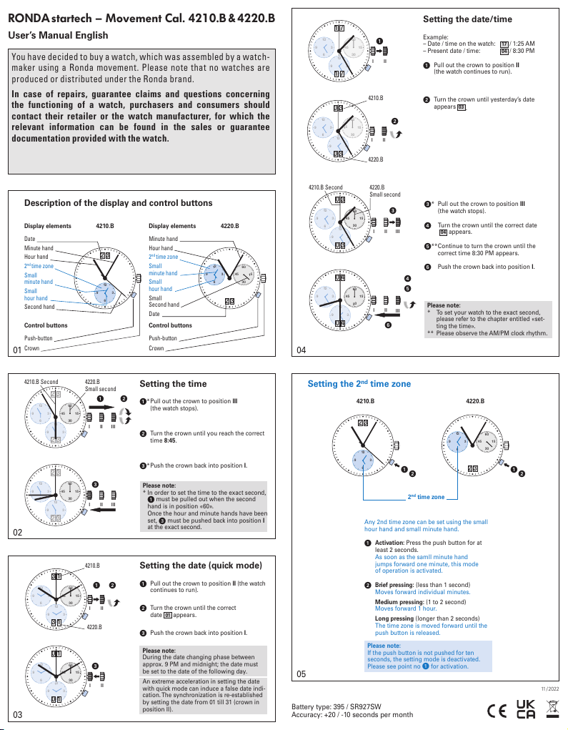
Description of the display and control buttons
Display elements 4210.B
Date
Minute hand
Hour hand
2nd time zone
Small
minute hand
Small
hour hand
Second hand
Display elements 4220.B
Minute hand
Hour hand
2nd time zone
Small
minute hand
Small
hour hand
Small
Second hand
Date
Control buttons
Push-button
Crown
Control buttons
Push-button
Crown
Setting the time
*
Pull out the crown to position III
(the watch stops).
Turn the crown until you reach the correct
time 8:45.
*Push the crown back into position I.
Please note:
* In order to set the time to the exact second,
must be pulled out when the second
hand is in position «60».
Once the hour and minute hands have been
set,
must be pushed back into position I
at the exact second.
4220.B
Small second
4210.B Second
Setting the date (quick mode)
Pull out the crown to position II (the watch
continues to run).
Turn the crown until the correct
date 01 appears.
Push the crown back into position I.
Please note:
During the date changing phase between
approx. 9 PM and midnight; the date must
be set to the date of the following day.
An extreme acceleration in setting the date
with quick mode can induce a false date indi-
cation.The synchronization is re-established
by setting the date from 01 till 31 (crown in
position II).
4210.B
4220.B
Setting the date/time
Example:
– Date / time on the watch: 17 / 1:25 AM
– Present date / time: 04 / 8:30 PM
Pull out the crown to position II
(the watch continues to run).
Turn the crown until yesterday’s date
appears
03 .
* Pull out the crown to position III
(the watch stops).
Turn the crown until the correct date
04 appears.
**Continue to turn the crown until the
correct time 8:30 PM appears.
Push the crown back into position I.
Please note:
* To set your watch to the exact second,
please refer to the chapter entitled «set-
ting the time».
** Please observe the AM/PM clock rhythm.
4220.B
Small second
4210.B Second
Setting the 2nd time zone
4210.B 4220.B
2nd time zone
Any 2nd time zone can be set using the small
hour hand and small minute hand.
Activation: Press the push button for at
least 2 seconds.
As soon as the samll minute hand
jumps forward one minute, this mode
of operation is activated.
Brief pressing: (less than 1 second)
Moves forward individual minutes.
Medium pressing: (1 to 2 second)
Moves forward 1 hour.
Long pressing (longer than 2 seconds)
The time zone is moved forward until the
push button is released.
Please note:
If the push button is not pushed for ten
seconds, the setting mode is deactivated.
Please see point no
for activation.
User’s Manual English
RONDAstartech – Movement Cal. 4210.B&4220.B
You have decided to buy a watch, which was assembled by a watch-
maker using a Ronda movement. Please note that no watches are
produced or distributed under the Ronda brand.
In case of repairs, guarantee claims and questions concerning
the functioning of a watch, purchasers and consumers should
contact their retailer or the watch manufacturer, for which the
relevant information can be found in the sales or guarantee
documentation provided with the watch.
11 /2022
Battery type: 395 / SR927SW
Accuracy: +20 / -10 seconds per month
01
02
04
03
05

Technical Instructions 4220.B
10/2013 M RONDA AG, Lausen, Switzerland, Phone ++41 (0)61 926 50 00, www.ronda.ch, [email protected] 1
2000.574.G Main plate
1.
3305.290.CO Cannon pinion with driver (Aig.2, closed)
2.
3301.243 Hour wheel (counter 12h)
3.
2030.017.CO Centre bridge
4. Centre bridge held by 1 screw 4000.250. Parts 2030.017.CO, 3004.223
and 3500.059 must be exchanged together.
4000.250 Screw
5.
3001.055.FI Sliding pinion
6.
3000.177.CO Setting stem
7.
3017.049 Setting lever
8.
3905.049 Setting lever jumper (3 positions)
9. Setting lever jumper tenue par 1 vis 4000.250.
4000.250 Screw
10.
3015.081 Yoke (3 positions)
11.
3905.067 Yoke spring
12. Tensioning the spring arm. Parts 3015.081 and 3905.067 must be
exchanged together.
3406.030 Pusher jumper B
13. Put the grey jumper between the two posts on the further side.
3406.038 Pusher jumper A
14. Put the yellow jumper between the two posts on the closer side.
3622.040 Stator
15. Mark |Z| on stator.
3622.039 Stator (counter 6h, 9h, chrono)
16.
3603.079 Plastic bracket
17. Plastic bracket held by 1 screw 4000.250.
4000.250 Screw
18.
3715.094.RK Rotor
19.
A
B
C

Technical Instructions 4220.B
10/2013 M RONDA AG, Lausen, Switzerland, Phone ++41 (0)61 926 50 00, www.ronda.ch, [email protected] 2
3147.046.CO Intermediate wheel
20.
3136.142.CO Second wheel (long)
21.
3122.056.CO Third wheel
22.
2020.148.G Train wheel bridge
23. Train wheel bridge held by 3 screws 4000.250.
4000.250 Screw
24.
3715.095.RK Rotor
25.
3147.048.CO Intermediate wheel (counter)
26.
3007.055.CO Minute wheel (counter 12h)
27.
3402.007.CO Minute counting wheel (12h)
28.
2020.149.G Counter train wheel bridge
29. Counter train wheel bridge held by 3 screws 4000.250.
4000.250 Screw
30.
3621.053.RK Coil
31. Attention: Please hold the coil only on the grey coil core. Coil held by 1
screw 4000.250.
3621.054.RK Coil (counter 9h, chrono)
32. Attention: Please hold the coil only on the grey coil core.
3601.118 Contact strip
33. Contact strip held by 1 screw 4000.250.
4000.250 Screw
34.
3503.054 Tube
35.
3503.054 Tube
36.
3603.034 Battery insulator
37.
D
E
F

Technical Instructions 4220.B
10/2013 M RONDA AG, Lausen, Switzerland, Phone ++41 (0)61 926 50 00, www.ronda.ch, [email protected] 3
3612.144.4220 Electronic module
38. Electronic module held by 5 screws 4000.248. Electronic
measurements may be realised now.
4000.248 Screw
39.
3603.069 Circuit insulator
40.
3601.107.G Pusher contact spring
41.
2130.138.G.M01.4220B Electronic module cover
42. Electronic module cover held by 3 screws 4000.250.
3600.010.HGF Battery 395
43.
3601.109.G Bridle +
44. Bridle held by 1 screw 4000.250.
4000.250 Screw
45.
G
H

Technical Instructions 4220.B
10/2013 M RONDA AG, Lausen, Switzerland, Phone ++41 (0)61 926 50 00, www.ronda.ch, [email protected] 4
2000.574.G Main plate
46.
3004.164 Setting wheel
47.
3004.164 Setting wheel
48.
3007.054.CO Minute wheel
49.
2130.143 Minute train bridge
50. Minute train bridge held by 2 screws 4000.305.
4000.305 Screw
51.
3004.223 Tens indicator driving wheel
52. Parts 2030.017.CO, 3004.223 and 3500.059 must be exchanged
together. The short tooth of the tens indicator driving wheel must point
to the center of the movement.
3500.059 Tens jumper
53. Parts 2030.017.CO, 3004.223 and 3500.059 must be exchanged
together.
2130.142 Tens jumper maintaining plate
54. Tens jumper maintaining plate held by 2 screws 4000.306. Tensioning
the spring arm.
4010.306 Screw
55.
3301.242 Hour wheel (Aig.2)
56.
3315.016 Friction spring
57.
3004.224.CO Date indicator driving wheel
58.
3500.049 Date jumper
59.
I
J

Technical Instructions 4220.B
10/2013 M RONDA AG, Lausen, Switzerland, Phone ++41 (0)61 926 50 00, www.ronda.ch, [email protected] 5
3504.214.AD.1.A Units indicator (standard)
60. Nick of the indicator at 3 o`clock.
3147.054 Tens intermediate wheel
61.
2130.141 Date indicator maintaining plate
62. Date indicator maintaining plate held by 1 screw 4000.250.
3905.070 Date jumper spring
63. Insert the date jumper spring in the provided opening.
3504.215.AD.1.A Tens indicator (standard)
64. Nick of the indicator at 3 o`clock
2130.140.G Date mechanism maintaining plate
65. Date mechanism maintaining plate held by 2 screws 4000.250.
4000.250 Screw
66.
3506.072.G Dial support
67.
8200 Moebius 8200
68.
9014 Moebius 9014
69.
124 Jismaa 124
70.
9020 Moebius 9020
71.
K
L

10/2013RONDA AG, Lausen, Switzerland, Phone ++41 (0)61 926 50 00, www.ronda.ch, info@ronda.ch EM 1
Electronic measurements
4220.B
Battery
395
Voltage
1.55 V
Setting stem in p
osition I, calendar not in gear,
60 s measur
ing interval for rate and consumption:
Typ
ical consumption
Maximal
consumption
1.32 µA
1.65 µA
R
ate -10s/M. .. +20s/M.
Lower working voltage limit
1.20 V
Setting stem in position
III, 60 s measuring interval:
Typical consumption
Maximal consumption
0.10 µA
0.30 µA

10/2013RONDA AG, Lausen, Switzerland, Phone ++41 (0)61 926 50 00, www.ronda.ch, info@ronda.ch EM 2
Electronic measurements
4220.B
Coil resistance M1
1.90 kΩ.. 2.10 kΩ
Coil resistance M4
1.68 kΩ.. 1.88 kΩ
Coil
isolation M1/M4 ∞kΩ
Signal generator
(4.9 ms, 8 Hz):
Lower working voltage
limit M4 1.20 V

Technical Instructions 4220.B
10/2013 N RONDA AG, Lausen, Switzerland, Phone ++41 (0)61 926 50 00, www.ronda.ch, [email protected] 1
2000.574.G Main plate
1.
3305.290.CO Cannon pinion with driver (Aig.2, closed)
2.
3301.243 Hour wheel (counter 12h)
3.
2030.024.CO Centre bridge
4. Centre bridge held by 1 screw 4000.250.
4000.250 Screw
5.
3001.055.FI Sliding pinion
6.
3000.177.CO Setting stem
7.
3017.049 Setting lever
8.
3905.049 Setting lever jumper (3 positions)
9. Setting lever jumper tenue par 1 vis 4000.250.
4000.250 Screw
10.
3015.081 Yoke (3 positions)
11.
3905.067 Yoke spring
12. Tensioning the spring arm.
3406.030 Pusher jumper B
13. Put the grey jumper between the two posts on the further side.
3406.038 Pusher jumper A
14. Put the yellow jumper between the two posts on the closer side.
3622.040 Stator
15. Mark |Z| on stator.
3622.039 Stator (counter 6h, 9h, chrono)
16.
3603.079 Plastic bracket
17. Plastic bracket held by 1 screw 4000.250.
4000.250 Screw
18.
3715.094.RK Rotor
19.
A
B
C

Technical Instructions 4220.B
10/2013 N RONDA AG, Lausen, Switzerland, Phone ++41 (0)61 926 50 00, www.ronda.ch, [email protected] 2
3147.046.CO Intermediate wheel
20.
3136.142.CO Second wheel (long)
21.
3122.056.CO Third wheel
22.
2020.148.G Train wheel bridge
23. Train wheel bridge held by 3 screws 4000.250.
4000.250 Screw
24.
3715.095.RK Rotor
25.
3147.048.CO Intermediate wheel (counter)
26.
3007.055.CO Minute wheel (counter 12h)
27.
3402.007.CO Minute counting wheel (12h)
28.
2020.149.G Counter train wheel bridge
29. Counter train wheel bridge held by 3 screws 4000.250.
4000.250 Screw
30.
3621.053.RK Coil
31. Attention: Please hold the coil only on the grey coil core. Coil held by 1
screw 4000.250.
3621.054.RK Coil (counter 9h, chrono)
32. Attention: Please hold the coil only on the grey coil core.
3601.118 Contact strip
33. Contact strip held by 1 screw 4000.250.
4000.250 Screw
34.
3503.054 Tube
35.
3503.054 Tube
36.
3603.034 Battery insulator
37.
D
E
F

Technical Instructions 4220.B
10/2013 N RONDA AG, Lausen, Switzerland, Phone ++41 (0)61 926 50 00, www.ronda.ch, [email protected] 3
3612.144.4220 Electronic module
38. Electronic module held by 5 screws 4000.248. Electronic
measurements may be realised now.
4000.248 Screw
39.
3603.069 Circuit insulator
40.
3601.107.G Pusher contact spring
41.
2130.138.G.M01.4220B Electronic module cover
42. Electronic module cover held by 3 screws 4000.250.
3600.010.HGF Battery 395
43.
3601.109.G Bridle +
44. Bridle held by 1 screw 4000.250.
4000.250 Screw
45.
G
H

Technical Instructions 4220.B
10/2013 N RONDA AG, Lausen, Switzerland, Phone ++41 (0)61 926 50 00, www.ronda.ch, [email protected] 4
2000.574.G Main plate
46.
3004.164 Setting wheel
47.
3004.164 Setting wheel
48.
3007.054.CO Minute wheel
49.
2130.143 Minute train bridge
50. Minute train bridge held by 2 screws 4000.305.
4000.305 Screw
51.
3004.227 Tens indicator driving wheel
52. The short tooth of the tens indicator driving wheel must point to the
center of the movement.
3500.075 Tens jumper
53.
2130.142 Tens jumper maintaining plate
54. Tens jumper maintaining plate held by 2 screws 4000.306. Tensioning
the spring arm.
4010.306 Screw
55.
3301.242 Hour wheel (Aig.2)
56.
3315.016 Friction spring
57.
3004.224.CO Date indicator driving wheel
58.
3500.049 Date jumper
59.
I
J
Table of contents
Other Ronda Watch manuals

Ronda
Ronda Startech 5000 User manual

Ronda
Ronda 5010.B User manual

Ronda
Ronda Cal. 5020.B User manual

Ronda
Ronda normtech 6203.B User manual

Ronda
Ronda mecano User manual

Ronda
Ronda 4210.B User manual

Ronda
Ronda 706.1 User manual

Ronda
Ronda 706.1 User manual

Ronda
Ronda normtech 700 User manual

Ronda
Ronda NORMTECH 788 User manual

Ronda
Ronda startech 5020.B User manual

Ronda
Ronda 3540.D User manual

Ronda
Ronda Xtratech User manual

Ronda
Ronda Startech 5030.D User manual

Ronda
Ronda startech 5040.F User manual

Ronda
Ronda startech 5050.C User manual

Ronda
Ronda Z60 User manual

Ronda
Ronda Mastertech 8000 Owner's manual

Ronda
Ronda 3540.D User manual

Ronda
Ronda Cal. 5130.D User manual